
Meraki Reference Architecture - Small Office Business
Overview
This document explores the details of an example architecture for what a Cisco Meraki small business network could look like. It serves as a reference architecture upon which similar small business networks can be based. In this example, a small, fictitious business, which we'll call "Ikarem Digital Services," is setting up a new office space with a full-stack Meraki network. We will learn about Ikarem's network requirements, design a network to satisfy those requirements, and examine the configurations of the completed network. While the configurations described in this document fully serve the needs of the example network, bear in mind that every network's requirements are unique and will likely vary from this example.
Network Requirements
The example small business in this scenario, Ikarem, has 10 employees and may have around three guests visiting the office at a time. Employees may be demonstrating services to customers in the office, working with existing customers at job sites, or working on new projects remotely. Ikarem owns a number of audio and video assets that technicians will take to customer job sites. These are otherwise stored in a secure location at the office.
Ikarem relies on a mix of cloud and locally hosted services. A web server at the office hosts a portfolio of services and previous customer projects. Project data stored on a separate server at the office must be securely accessible to employees both local and remote.
Employee laptops may connect to the wired network through a desk phone's connection or may move with the user throughout the office on the wireless. Guests visiting the office should have access to wireless but for internet access only.
A site-to-site VPN may or may not be required to connect to a data center or other office in a similar architecture, but Ikarem is operating on their own in this example.
The business needs above form the following network requirements:
- A client VPN service for remote workers to access network resources securely
- Network IPS and malware scanning for client and server security
- Segregated networks for guest and internal users
- Basic wireless. A site survey determines the quantity and placement of four wireless access points throughout the office to ensure adequate wireless coverage. Check out our documentation to learn more about Conducting Site Surveys with MR Access Points.
- Video surveillance for assets in the audio and video equipment room. Two cameras will provide multiple vantage points of the room entrance. Check out our documentation to learn more about Designing Meraki MV Smart Camera Solutions.
- PoE+ support for desk phones, smart cameras, and wireless access points
- Up to 41 active client devices expected at once:
- 10 employees, each with a desk phone, laptop, and smartphone (30 devices)
- Three guests with 1-2 devices each (6 devices)
- 2 servers
- 2 MV smart cameras
- 1 printer
Topology
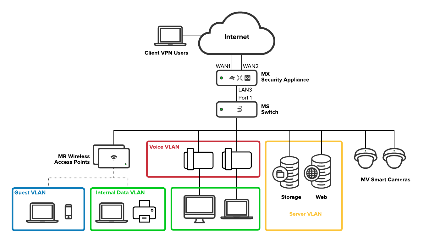
The network topology depicts how each piece of the solution fits into place to fulfill the network requirements.
The network has been segmented into separate VLANs for each general use-case for the network:
- Internal Data
- Voice
- Server
- Guest
Segmenting the network allows for greater control over traffic to and from each subnet. Segmentation allows for separate configurations of, for example, uplink flow preferences, traffic shaping, and firewall rule configuration per subnet. There will be more details on these later in the document.
In this topology, Meraki devices, such as the switch, wireless access points, and MV smart cameras, obtain IP addresses on the internal data VLAN along with other clients on the wired network. These IPs are used for management communication with the Meraki dashboard. Network management traffic and internal data on the same VLAN is not a problem for a small network, such as in this example. However, as the business grows and the network becomes more complex, Ikarem may choose to implement more granular VLAN segmentation to increase control over the flow of traffic.
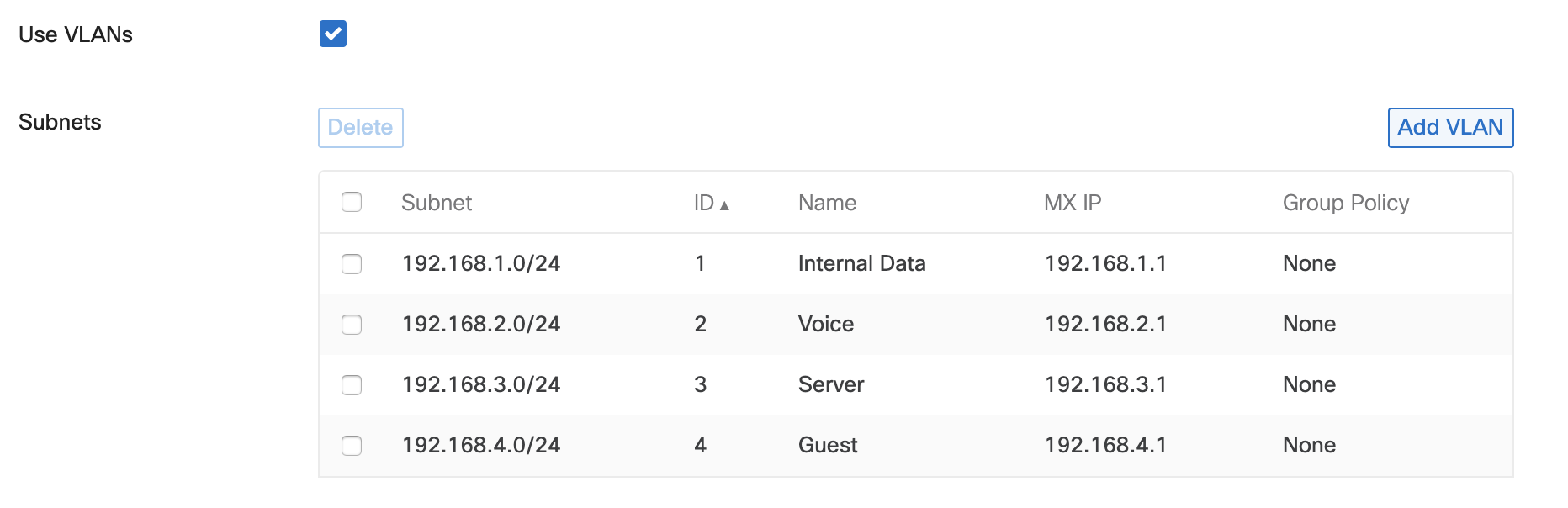
Subnetting Scheme
A separate VLAN is created for each general network use-case. The following table breaks down the VLAN ID and subnet that serves each use-case.
Note that client VPN does not belong to a particular VLAN. As you will see later in this document, client VPN is configured separately from other local VLANs. However, a unique subnet is still required so the MX can assign IP addresses to remote VPN clients and route their traffic to and from the office subnets.
| Network Use-case | VLAN ID | Subnet |
|
Internal Data |
1 |
192.168.1.0/24 |
| Voice | 2 | 192.168.2.0/24 |
| Server | 3 | 192.168.3.0/24 |
| Guest | 4 | 192.168.4.0/24 |
| Client VPN | N/A | 192.168.5.0/24 |
IP Addressing
The following table contains the expected VLAN and IP address for each device on this network.
The MX has two WAN interfaces to provide redundant internet connectivity. The other LAN IP addresses assigned to the MX serve as the default gateway IPs for devices on their respective VLANs.
| Device | VLAN(s) | IP Addressing |
| MX67 security appliance |
1 - Internal Data 2 - Voice 3 - Server 4 - Guest |
WAN WAN1: Static IP provided by ISP1 WAN2: DHCP IP provided by ISP2 LAN Internal Data: 192.168.1.1 Voice: 192.168.2.1 Server: 192.168.3.1 Guest: 192.168.4.1 |
| MS120-48LP switch | 1 - Internal Data | DHCP |
| 4x MR20 wireless access points | 1 - Internal Data | DHCP |
| 2x MV12N smart cameras | 1 - Internal Data | DHCP |
| Storage server | 3 - Server | 192.168.3.2 (static) |
| Web server | 3 - Server | 192.168.3.3 (static) |
| Printer | 1 - Internal Data | DHCP Fixed IP |
| Desk phones | 2 - Voice | DHCP |
| Guest devices | 4 - Guest | DHCP |
| Client VPN devices | N/A | DHCP |
Configurations
Now that we have an overview of the network requirements and the parts involved in the solution, we will take a detailed look at the configurations in place to see how each device will serve its purpose.
Security & SD-WAN
This section will examine the configurations for the MX security appliance.
Uplinks
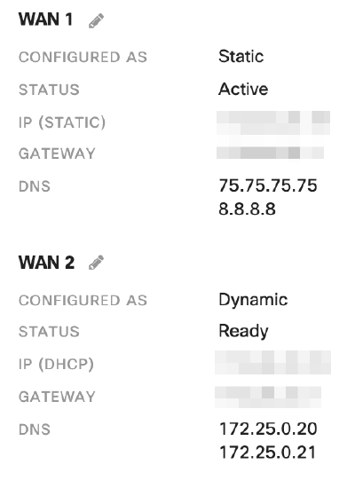
Ikarem's web server must be accessible from a consistent public IP address. The MX has an 'Internet 1' port (WAN1) that is configured with the static public IP provided by WAN1's internet service provider (ISP) to accommodate this requirement. For more information on configuring static IP addresses for an MX WAN interface, refer to our document on Using the Cisco Meraki Device Local Status Page.
WAN1's first DNS server belongs to the ISP. The second DNS server belongs to a separate, well-known public DNS service, Google Public DNS. In the event the ISP DNS server is unreachable, WAN1 can still operate properly using the public DNS service.
A second ISP provides backup internet connectivity on the MX secondary uplink. This ISP provides an address to the MX WAN2 interface dynamically.
Addressing & VLANs
The MX is in Routed mode to act as a layer 3 gateway to LAN devices, provide DHCP IP addresses, NAT traffic to the internet, and control network traffic between VLANs.
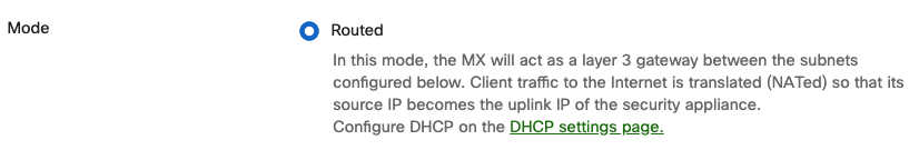
The MX uses a separate VLAN for each general use case for the network.
DHCP
The MX is configured to serve DHCP IP addresses for each VLAN so that devices automatically obtain IP addresses.
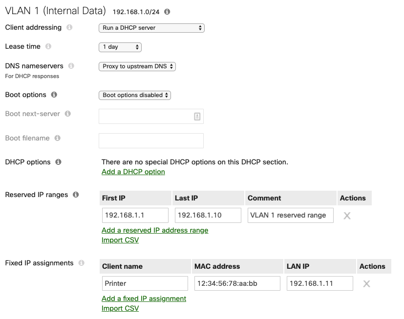
Each subnet's DHCP scope reserves a range of 10 IP addresses for any network devices (such as Meraki hardware, or printers) that may require static IPs.
The Internal Data VLAN's DHCP scope fixes a specific IP for the MAC address of the network printer. The printer itself is not configured with a static IP but will always obtain a consistent DHCP IP address from the MX when it asks for one on VLAN 1.
Firewall
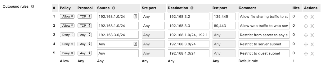
The MX allows outbound traffic by default. Outbound traffic includes client traffic destined for the internet or other subnets on the LAN. In this case, traffic between certain subnets is restricted to only what is necessary to satisfy the business needs.
Layer 3 outbound firewall rules are processed from the top down and action is taken on the first matched rule. So the most specific rules are closest to the top where they will be processed first. Check out our documentation to learn more about Using Layer 3 Firewall Rules.
Here is a breakdown of each layer 3 firewall rule:
- Allow storage traffic from the internal data subnet to the server.
- Allow web traffic to from the internal data subnet to the web server.
- Deny any traffic initiated from the server subnet to other subnets. Traffic need only be initiated from clients to the server as configured in rules 1 and 2.
- This rule works in conjunction with rules 1 and 2. Deny any traffic to the server subnet that wasn't already allowed in rules 1 or 2.
- Deny any traffic initiated to the guest subnet.
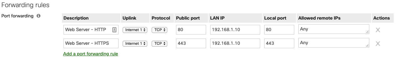
The MX denies inbound traffic by default. Inbound connections from the internet require forwarding or NAT rules. TCP port 80 and 443 are allowed inbound and forwarded to the local web server to support external access to the local web server.
Client VPN
Client VPN is enabled and listening for inbound client VPN connection attempts from clients at remote locations that need to access files stored on the local storage server.

A unique subnet is configured for client VPN devices. The MX assigns an IP address from this subnet to devices that successfully authenticate to the client VPN.
Users that require access to client VPN are added to the user list for Meraki cloud authentication. Check out our documentation for more details on Managing User Accounts using Meraki Authentication.
Remote client devices are configured to connect to Client VPN separately. See our document on Client VPN OS Configuration for step by step instructions on configuring clients for Client VPN.
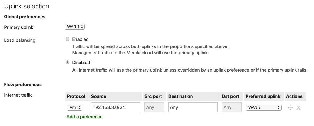
SD-WAN & Traffic Shaping
Each MX uplink is configured to match the throughput expected of its ISP. Uplink throughput settings are taken into consideration for traffic priority and uplink load balancing.
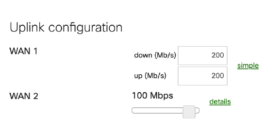
The most suitable uplink for internal user needs (in this case, the uplink with the highest available bandwidth, WAN1) is selected as the primary uplink. All client traffic destined for the internet will use this uplink unless otherwise specified in the Flow preferences. Internet traffic from the Guest VLAN's subnet prefers WAN 2 to further reduce conflict for bandwidth between guest traffic and internal traffic. Additionally, in the event of a complete outage on WAN1, Ikarem's network will still have internet access using WAN2.
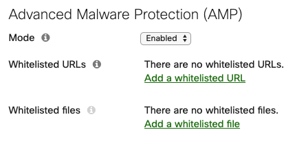
Threat Protection
This feature requires an Advanced Security license.
Advanced Malware Protection (AMP) is enabled network-wide for scanning HTTP downloads for whether they have a malicious disposition.
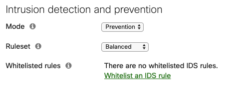
Intrusion detection and prevention is enabled in Prevention mode with a Balanced ruleset to identify and block malicious traffic patterns.
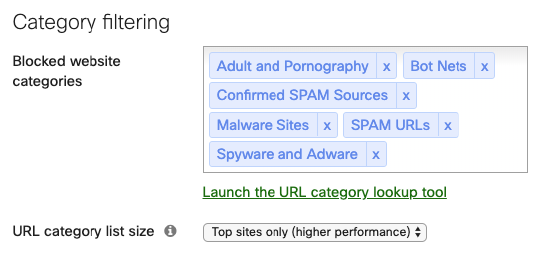
Content Filtering
This feature requires an Advanced Security license.
Content filtering is enabled and configured to block site categories that are inappropriate or unsafe to visit.
Switch
This section will examine the configurations on the MS120-48LP Switch.
Settings
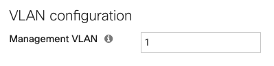
Any MS switch added to the dashboard network uses VLAN 1 for management traffic by default. Ikarem has opted to use the Internal Data VLAN 1 for Meraki device management IPs.
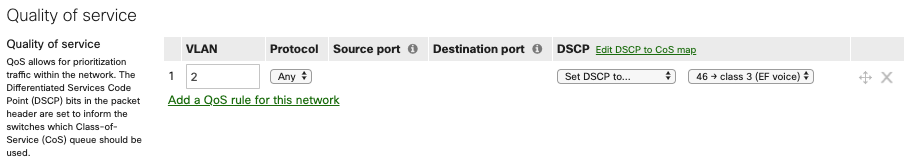
QoS on the switches prioritizes traffic on the voice VLAN (VLAN 2) and adds DSCP traffic to signal to other devices that they should prioritize it as well. Check out our documentation to learn more about MS Switch Quality of Service.
Switch ports
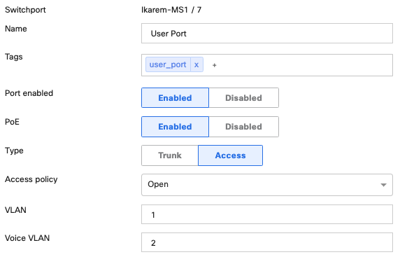
Power over Ethernet (PoE) is enabled on all MS120-48LP RJ-45 switch ports by default. The switch automatically provides power based on the current used by the connected device. For example, 802.3af for MV12 smart cameras and desk phones, or 802.3at (PoE+) for MR20 access points. Check out our documentation to learn more about PoE Support on MS Switches.
Switch ports that serve employees are configured for access mode with VLAN 1. These ports are also configured with a voice VLAN so that connected desk phones are automatically placed in VLAN 2.
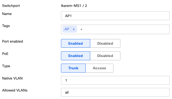
Switch ports serving access points are configured for trunk native VLAN 1. When the access point is connected to the switch port, it obtains an IP on the native VLAN. Traffic for wireless SSIDs that tag a certain VLAN will pass through the switch port in trunk mode with Allowed VLANs 'all'.
Wireless
This section will examine the configurations for the MR20 wireless access points.
Access Points
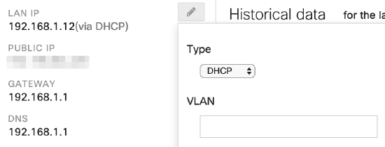
Access points are connected to the allotted switch ports to receive PoE+ and trunk mode with native VLAN 1. The VLAN field is left blank in each AP's management IP configuration. When the AP is connected to the switch port, it will obtain an IP on the native VLAN.
Access Control
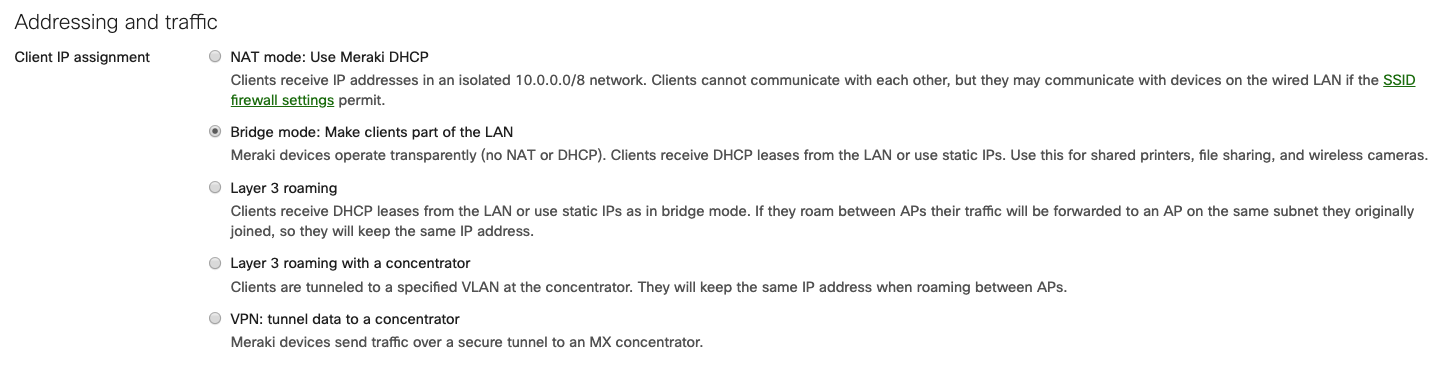
Two SSIDs exist to serve two use-cases for the wireless network: "Ikarem" for employee use, and "Ikarem Guest" for guest use. Both SSIDs use Bridge mode so that wireless clients obtain DHCP addresses from the MX on the appropriate VLAN.
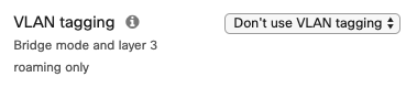
Clients connecting to the Ikarem SSID for employee access are placed on VLAN 1, the native VLAN for the AP's switch port, by selecting Don't use VLAN tagging.
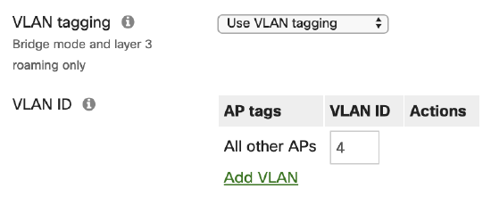
Clients connecting to the "Ikarem Guest" SSID are placed onto VLAN 4 through the use of tagging on the SSID. Use VLAN tagging is selected with VLAN ID 4 specified. All traffic from clients on this SSID is placed onto VLAN 4 where the security appliance handles uplink preference as described in the Security & SD-WAN section of this document.
Firewall & Traffic Shaping
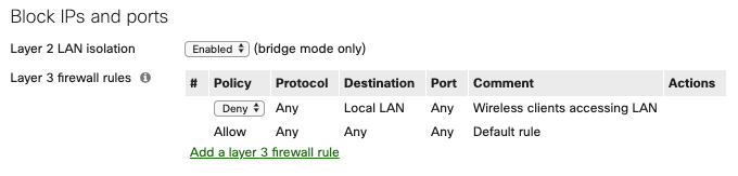
While guests are allowed access to the wireless network, they are restricted to internet access only. Firewall rules for the guest SSID are implemented on the access points via Wireless > Firewall & traffic shaping. Layer 2 LAN isolation is enabled to only allow clients on the SSID to communicate with the default gateway MAC address. Check out our documentation to learn more about Wireless Client Isolation. Layer 3 firewall rules for the guest SSID deny traffic to all LAN destinations to prevent communication to any other private subnet that may exist on the LAN.
Traffic shaping rules limit the bandwidth available to the guest network. The Per-SSID bandwidth limit restricts the Ikarem Guest SSID to 30 Mbps total (10 Mbps per user = 10240 Kbps, times 3 expected guests = 30720 Kbps). Additional guests can connect and use the network, but will not use more than the allotted bandwidth.

Highest rated
(rating)Recently updated
(date updated)Recently added
(date created)