
MG51/MG51E Installation Guide
By Unni Rajagopalan
About this Guide
This guide provides instruction on how to install and configure your MG51/MG51E series device. This guide also provides mounting instructions and limited troubleshooting procedures. For more MX device installation guides, refer to the MX installation guides section on our documentation website.
Product Overview
Connectivity is critical for any organization that depends on reliable internet access in order to function. Wireless WAN connectivity options, such as cellular networks, serve as a reliable backup internet uplink in the event of a primary uplink failure.
The gigabit capable MG51/MG51E cellular gateway simplifies the path to wireless WAN connectivity and makes cellular a viable uplink option for many networks. The MG51/MG51E acts as a gateway to cellular networks by converting 5G and LTE signal from a cellular provider to an Ethernet handoff, which can be used as an internet uplink for a variety of use-cases.
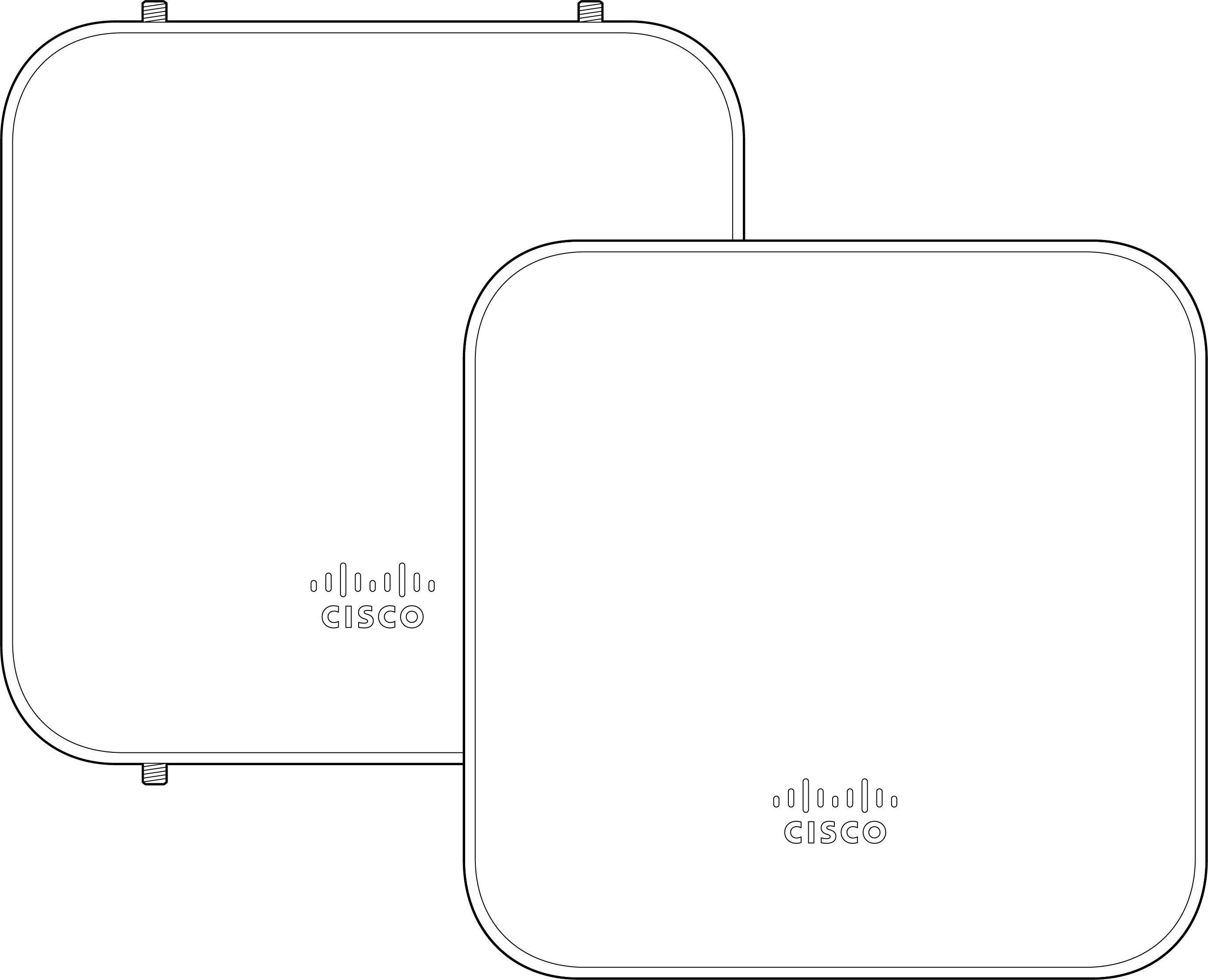
Product View and Physical Features
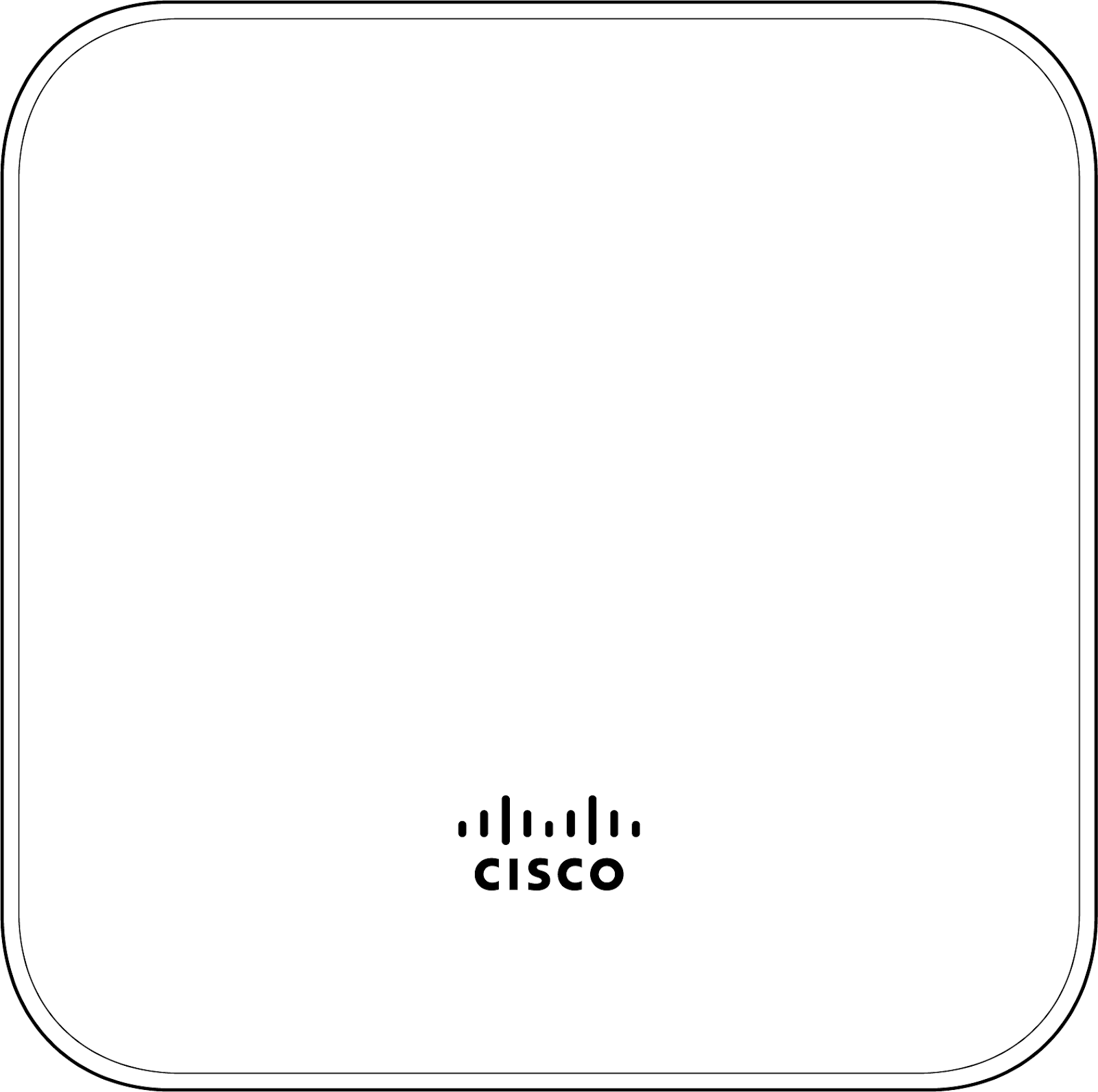
MG51-HW
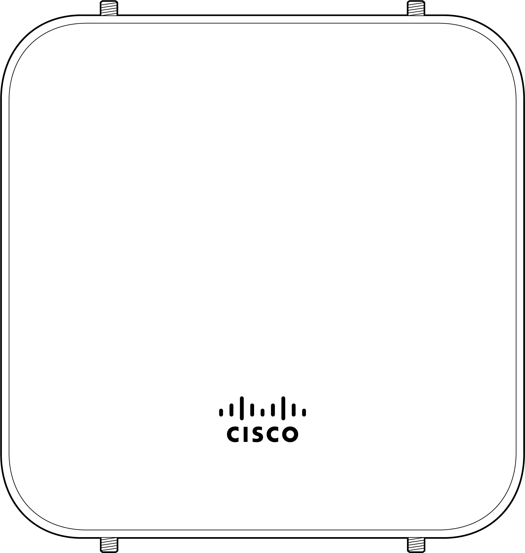
Front Panel
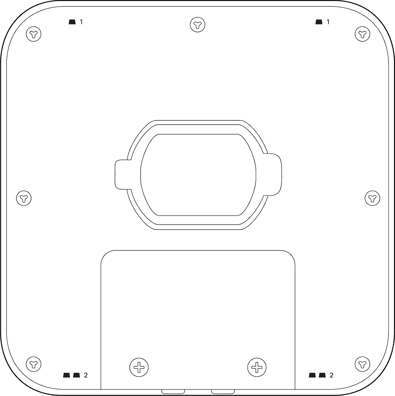
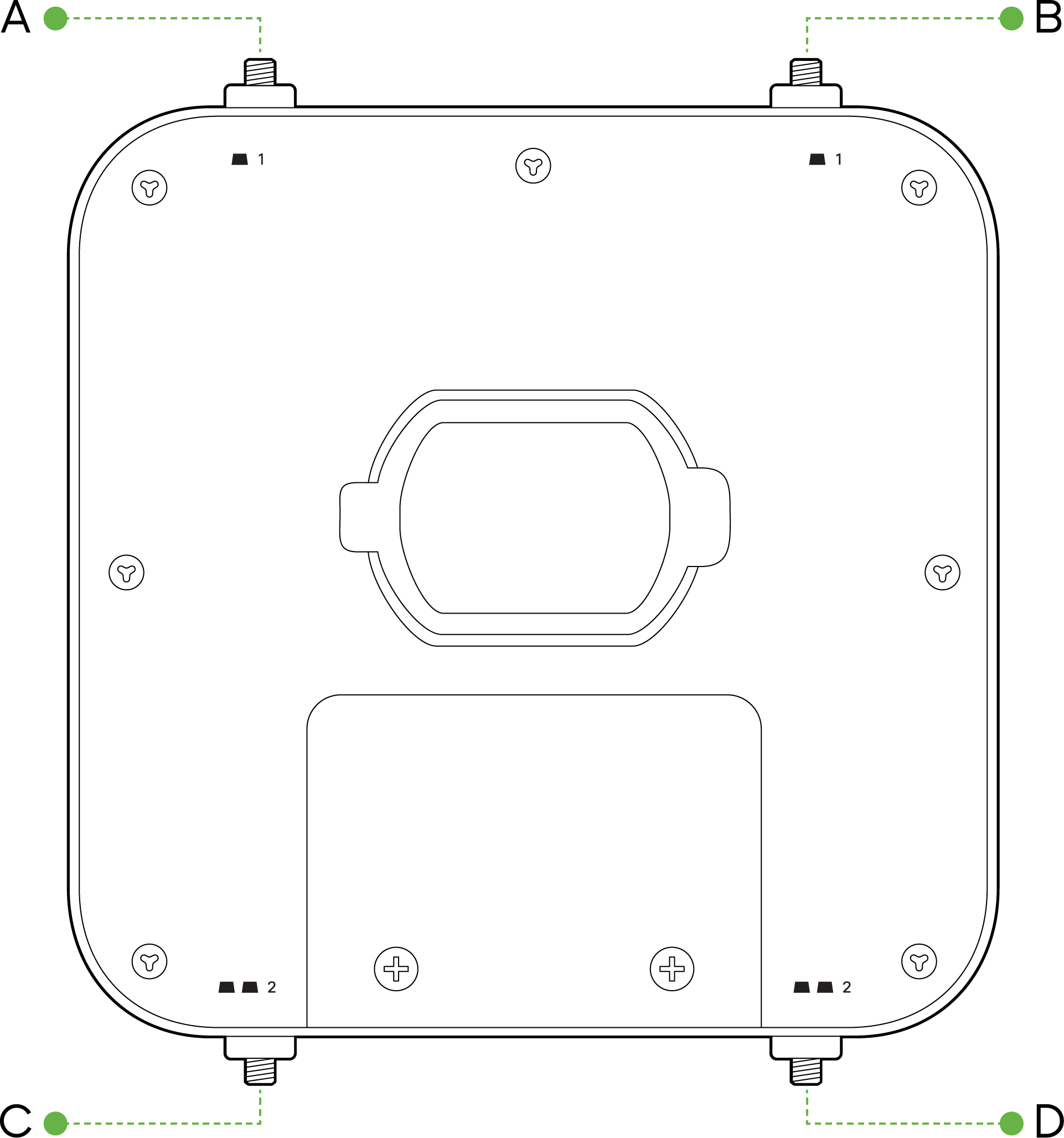
Back Panel
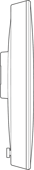
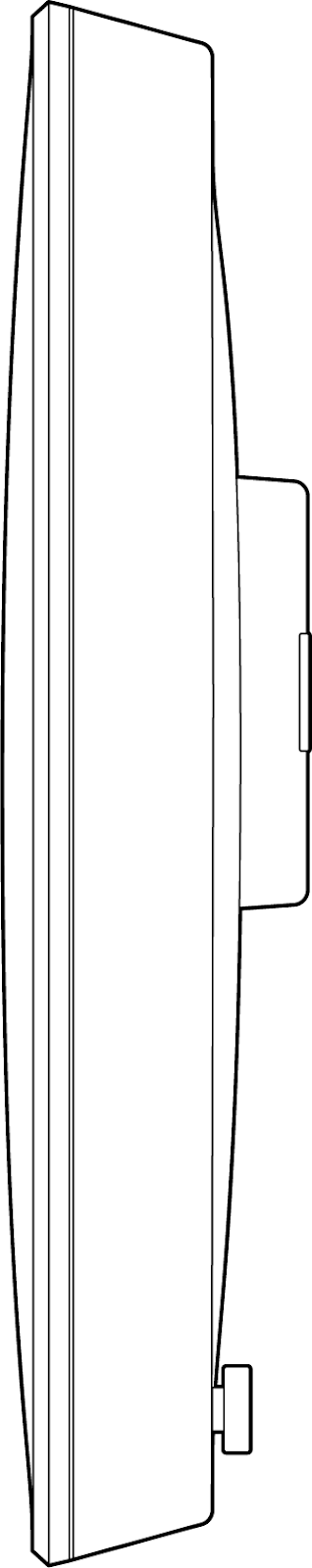
Side Panels
MG51E-HW
Front Panel
Back Panel
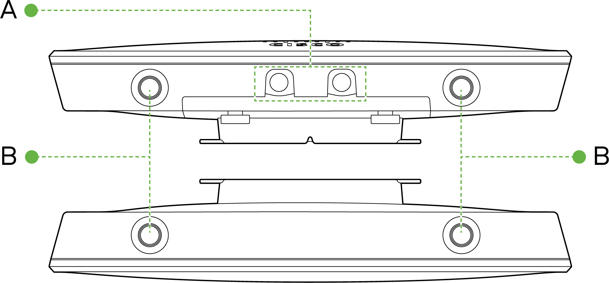
Top & Bottom View
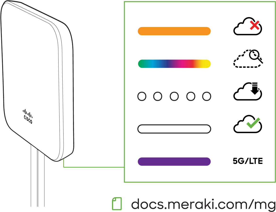
Status Indicator
The MG series of devices use an LED to inform the user of the device's status. LED patterns and their meanings are described below.
|
LED Status |
Meaning |
|
Solid orange |
Power is applied but the appliance is not connected to the Meraki Dashboard |
|
Rainbow Colors |
The appliance is attempting to connect to Meraki Dashboard |
|
Flashing White |
Firmware upgrade in progress |
|
Solid White |
Fully operational/connected to LAN |
| Solid Purple | Fully operational/connected to cellular network |
Ethernet Port
The MG51/MG51E features two Ethernet ports. Port 1 can be reconfigured to Safe Mode for troubleshooting and diagnostics. Brand new units will ship with both ports configured as LAN, which is the default, normal operating mode.
The port labeled “PoE” (Port 1 & 2) accepts 802.3at power.

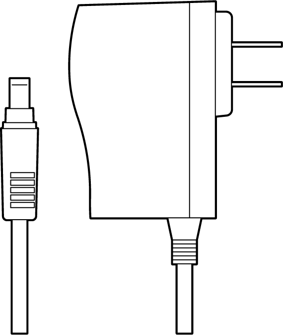
AC Adapter Power Port
In the event that the MG cannot be powered by POE, the MG has an AC adapter port that can be used to power it up with the 30watt (12V 2.5A) AC adapter (sold separately).
Factory Reset
To reset an MG cellular gateway to the factory defaults, press the button labeled 'Reset' on the back panel of the appliance for at least 10 seconds. This will clear all the local configuration settings done via the local status page. Please be aware that after resetting the unit, the local status page requires reconfiguration, and the device will need to download its latest configuration from the dashboard cloud. Please be patient as this could take up to 5 - 10 minutes.
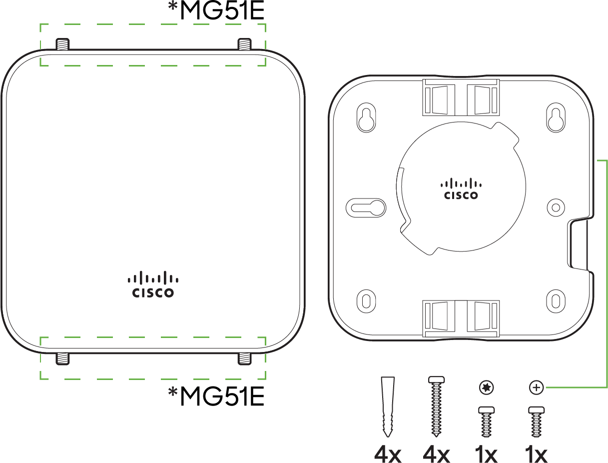
Package Contents
| Model | Contents |
|---|---|
| MG51 | 1 x MG51-HW 1 x Mounting plate |
| MG51E | 1 x MG51E-HW 1 x Mounting plate 4 x dipole antennas |
Note: Non-Meraki antennas are not supported. The socket is a reversed RP-SMA that is designed to detect the official MG smart dipole antennas and smart patch antenna. Usage of non-Meraki accessories may damage the MG and degrade performance. The Cisco Meraki antennas are designed for the maximum allowable gain without exceeding the EIRP for local regulatory domains on their supported bands.
Safety and Warnings
These operations are to be taken with respect to all local laws. Please take the following into consideration for safe operation:
-
Power off the unit before you begin. Read the installation instructions before connecting the system to a power source.
-
Before you work on any equipment, be aware of the hazards involved with electrical circuitry and be familiar with standard practices for preventing accidents.
-
Read the mounting instructions carefully before beginning installation. Failure to use the correct hardware or to follow the correct procedures could result in a hazardous situation to people and damage to the system.
-
This product relies on the building’s installation for short-circuit (over current) protection. Ensure that the protective device is rated not greater than: 15 A, 125 Vac, or 10A, 240 Vac.
-
Please only power the device with the provided power cables to ensure regulatory compliance.
Pre-install Preparation
You should complete the following steps before going on-site to perform an installation.
Configure the Dashboard Network
The following is a brief overview only of the steps required to add an MG51/MG51E to your network. For detailed instructions about creating, configuring and managing Meraki networks, refer to our online documentation portal.
-
Login to http://dashboard.meraki.com and select the intended organization. If this is your first time using the Meraki dashboard, create a new account.
-
Claim the device to your organization inventory. You will need your Meraki order number (found on your invoice) or the serial number of each MG, which looks like Qxxx-xxxx-xxxx, and is found on the bottom of the unit. You will also need to claim your Enterprise license key, which you should have received via email.
-
Find or create the network to which you plan to add your MG51/MG51E.
Check and Set Firmware
To ensure your MG51/MG51E performs optimally immediately following installation, it is recommended that you facilitate a firmware upgrade prior to using your MG51/MG51E.
-
Insert an active nano (4FF) SIM card/cards into the SIM trays before powering up the device.
-
Connect your MG51/MG51E to power.
-
The MG51/MG51E will turn on and the power LED will glow solid orange until it comes online.
-
If the unit requires a firmware upgrade after coming online, the power LED will begin blinking white until the upgrade is complete, at which point the LED will turn solid white. You should allow at least a few minutes for the firmware upgrade to complete, depending on the speed of your internet connection.
Check and Configure Upstream Firewall Settings
If you are testing safe mode on port 1 and have an upstream firewall in place, the firewall must allow outgoing connections on particular ports to specific IP addresses. The most current list of outbound ports and IP addresses for your organization can be found on the Help > Firewall Information page in your dashboard.
Collect Tools
You will need the following tools to perform an installation:
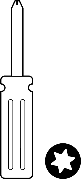


T8 Torx screwdriver, Phillips screwdriver, Hammer, Drill with 1/4" (6.3mm) bits
Collect Additional Hardware for Installation
You will need the following hardware to perform an installation:

802.3af PoE source (either PoE switch or Meraki 802.3af PoE injector), AC adapter, Network cables RJ45 connectors long enough for your particular mounting location
Installation Instructions
Mounting Hardware
The supplied wall screws and anchors allow you to mount the appliance on a drywall surface, either vertically or horizontally. For mounting on drywall, use a ¼-inch drill bit, then insert the plastic and screw assemblies.
-
For mounting on wood or a similar surface, use only the screws.
-
Allow the heads of the screws to stick out far enough to be inserted securely into the back of the MG.
Plan Ahead: When mounting the MG cellular gateway in hard to reach areas, it is recommended that Ethernet cables are run to both ports as a redundant method to access both ports in the case of physical failure of a port or cable.
.png?revision=1)
Picture credits - Jade Neyroud
Connecting to WAN
All Meraki MG devices must have an IP address. This section describes how to configure the WAN interface before you deploy it. A local management web service running on the appliance is accessed through a browser running on a client PC. This web service is used for configuring and monitoring basic ISP/WAN connectivity.
Note: All the settings below are accessible only via the local status page.
Setting up Cellular Connection
Warning: To ensure that the client PC is redirected to the local web service in the following steps, you must disable all other network services (ex: wi-fi) on your client machine.
Follow the steps below to configure basic connectivity and other cellular gateway parameters on the MG51/MG51E:
-
Using a client machine such as a laptop, connect directly to LAN interface of the MG.
-
Find the client's IP address and default gateway. Using a browser on the client machine, access the appliance's built-in web service by browsing to mg.meraki.com or the default gateway IP (You do not have to be connected to the Internet to reach this address).
-
Click the Configuration tab under the local status tab. The default credentials are the Serial Number of the device (all upper-case with dashes) as the username and a blank password field.
4. Configure additional bearer values like APN if required by your carrier under the Configuration tab.
Configuring Ethernet Ports
To configure physical link settings on the Ethernet ports, click on Ethernet tab. You can enable half duplex, full duplex, and auto-negotiation, as well as set 10 or 100 or 1000-Mbps data rates on Ethernet ports.
Basic Troubleshooting
The following steps can be used for troubleshooting basic connectivity issues with your MG:
- MG devices require a valid and active data plan, so make sure the SIM and data plan are active. SIM size for MG51/51E is nano (4FF).
- Some carriers require specific APNs, usernames/passwords. Ensure the values are correct if required.
- Validate signal quality is sufficient by checking the RSRP and RSRQ values on the Connection tab of the local status page.
- Swap the SIM card to the secondary SIM slot from the primary slot (A new unit will treat SIM slot 1 as primary unless changed via dashboard/local status page)
- Try connecting the MG in Safe Mode and check if it comes online on Dashboard.
- Try a soft reset by pressing the reset button for 1 second to delete a downloaded configuration and reboot the MG.
- Try a factory reset by holding the factory reset button for at least 10 seconds.
- Try switching cables, or testing your cables on another device.
If the MG51/E fails to get online or the LED remains RED after all the above steps. Please check the local status page and move your device to an area where the signal conditions are better.
How do I know if my MG51 is using 5G?
MG51 use a 5G technology known as 5G NSA (Non-Standalone). The alternative to this is known as 5G SA (Standalone). The core difference between these technologies (NSA / SA) is in the control signaling of the Radio Access Network (RAN). For NSA 5G, the control signaling is anchored to the 4G LTE network and requires a 4G LTE connection to establish before being able to establish the 5G service. Essentially, a 5G NSA connection is required to be built on top of an existing 4G LTE connection.
This differs from 5G SA, where the control signaling is handled directly on the 5G network. This allows the 5G SA connection to be established purely over 5G without the requirement of a 4G LTE connection. This stepping stone technology (5G NSA) allows providers to more easily and quickly integrate 5G connectivity into their existing networks and ease the transition from an existing 4G LTE network to full 5G SA network.
Via Dashboard:
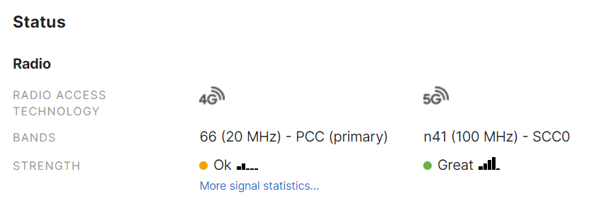
Within the Uplink tab of the MG status page on dashboard, the radio status section is displayed. For MG51 this displays both the current 4G and 5G radio status including current bands and signal strength.
When the MG has established a 5G connection the radio status of both the 4G LTE and 5G NSA radio will be displayed:
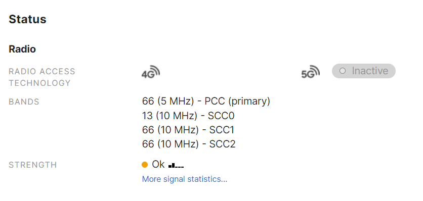
When a 5G connection is not in use, the 5G status will show "Inactive":
Device power issue
-
If device fails to turn on, check the power source to make sure it is adequately supplying power to the MG.
-
If there are no LED lights even though there is power at the outlet, check the MG to make sure everything is plugged in properly.
- If device isn't coming after trying both AC adapter and POE, check that the power options also work on other devices in a similar or matching setup.
If you are still experiencing hardware issues, please contact Cisco Meraki Support by logging in to dashboard and using the Help > Get Help option at the top of the page, then opening an email case or calling the Meraki Support center using the contact information on that page.
Warranty
MG Warranty coverage periods are as follows:
|
Product |
Warranty Period |
Warranty Information |
|---|---|---|
|
MG51/MG51E |
Lifetime |
Full lifetime hardware warranty with next-day advanced replacement included. Applies to MG51 and MG51E hardware |
|
MG Accessories |
1 Year |
The following are considered accessories: Includes mounting kits, antenna, and additional power cords |
Additional warranty information can be found on the Return Policy and Requesting a RMA page of the Cisco Meraki website.
If your Cisco Meraki device fails and the problem cannot be resolved by troubleshooting, contact support to address the issue. Once support determines that the device is in a failed state, they can process an RMA and send out a replacement device free of charge. In most circumstances, the RMA will include a pre-paid shipping label so the faulty equipment can be returned.
In order to initiate a hardware replacement for non-functioning hardware that is under warranty, you must have access to the original packaging the hardware was shipped in. The original hardware packaging includes device serial number and order information, and may be required for return shipping.
Meraki MG51 and MG51E devices have been tested and found to comply with the limits for a Class B digital device, pursuant to part 15 of the FCC rules. These limits are designed to provide reasonable protection against harmful interference in a residential installation. This equipment generates, uses, and can radiate radio frequency energy and, if not installed and used in accordance with the instructions, may cause harmful interference to radio communications. However, there is no guarantee that interference will not occur in a particular installation.
Support and Additional Information
If issues are encountered with device installation or additional help is required, contact Meraki Support by logging in to dashboard.meraki.com and opening a case by visiting the Help > Get Help page.
- The equipment is intended for industrial or other commercial activities.
- The equipment is used in areas without exposure to harmful and dangerous production factors, unless otherwise specified in the operational documentation and/or on the equipment labeling.
- The equipment is not for domestic use. The equipment is intended for operation without the constant presence of maintenance personnel.
- The equipment is subject to installation and maintenance by specialists with the appropriate qualifications, sufficient specialized knowledge, and skills.
- Rules and conditions for the sale of equipment are determined by the terms of contracts concluded by Cisco or authorized Cisco partners with equipment buyers.
- Disposal of a technical device at the end of its service life should be carried out in accordance with the requirements of all state regulations and laws.
- Do not throw in the device with household waste. The technical equipment is subject to storage and disposal in accordance with the organization's disposal procedure.
- The equipment should be stored in its original packaging in a room protected from atmospheric precipitation. The permissible temperature and humidity ranges during storage are specified in the Operation (Installation) Manual.
- Transportation of equipment should be carried out in the original packaging in covered vehicles by any means of transport. The temperature and humidity during transportation must comply with the permissible established ranges of temperature and humidity during storage (in the off state) specified in the Operation Manual (Installation).
For additional information on Meraki hardware and for other installation guides, please refer to documentation.meraki.com