
Meraki Auto RF: Wi-Fi Channel and Power Management
Learn more with these free online training courses on the Meraki Learning Hub:
Auto RF Overview
Auto RF is a feature on Meraki access points that is built on Auto TX Power and Auto Channel in order to detect non-Wi-Fi interference and monitor the Wi-Fi environment. Based on the environmental factors it detects, Auto RF can automatically tune settings such as channel assignments, per-radio transmit power, and band steering.
Auto RF samples data about the RF environment collected from each AP in a network and feeds it through a mathematical formula to derive an overall performance score for that particular AP. The product of all performance scores in the network then becomes the network's overall score, which is the ultimate factor when considering potential changes.
For all Artificial Intelligence powered by AI-Enhanced RRM features in Auto RF please refer to the AI-Powered Auto RF document.
A network's performance score is calculated in three different ways:
- Every 15 minutes, each AP's score is evaluated against neighbors that are zero hops away (i.e. immediately adjacent)
- Every 3 hours, each AP's score is evaluated against neighbors that are one hop away, and then zero hops away (i.e. its immediate neighbors, and their neighbors)
- Every 24 hours, each AP's score is evaluated against neighbors that are two hops away, then one, then zero.
Each evaluation is run ten times, and once that cycle is complete, Auto RF will push any changes to the current channel and power settings that will result in a net increase to the network's performance score.
When an AP is being deployed initially, it uses the default channels of 1 for 2.4 GHz and 36 for 5 GHz and the transmit power is set to Auto. These settings can be manually configured on the dashboard per AP before deploying wireless setup.
Auto Channel
Auto Channel dynamically adjusts the channels of the client-serving radios to avoid RF interference (both 802.11 and non-802.11) and develops a channel plan for the wireless network. Auto Channel is a good fit for most wireless networks, providing a baseline channel configuration that can then be adjusted manually if needed.
This section outlines how Auto Channel operates and how to interpret channel change events.
Configuration
Auto Channel is enabled by default on all Meraki access points. To ensure Auto Channel is enabled on an AP, navigate to Wireless > Configure > Radio settings in the dashboard and select a particular AP. The radio configuration for the access point will be displayed on the right-hand side of the page. The Auto Channel algorithm will be used on radios that have "Auto" selected for their channel and is performed every 15 minutes.
2.4 GHz Channel Selection
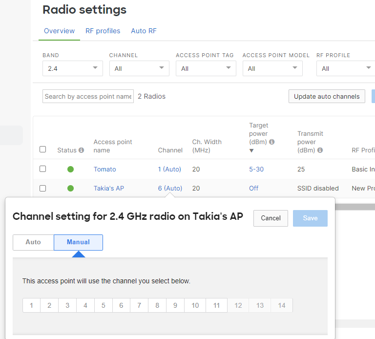
Meraki access points follow best practices and industry standards in the Auto Channel selection, so an AP's 2.4 GHz radio will only be set to channels 1, 6, and 11. Because they do not overlap in frequency, these three channels have the least amount of co-channel interference. Other channels are included in the list and may be selected manually to override the Auto Channel algorithm.
5 GHz Channel Selection
Channel availability for 5 GHz varies based on AP model and regulatory domain. The access point will consider any channel that it is certified for in the regulatory domain of operation. A list of channels can be viewed by opening the channel drop-down for the AP on the radio settings page. There is no preference for a particular band and all channels are weighed evenly.
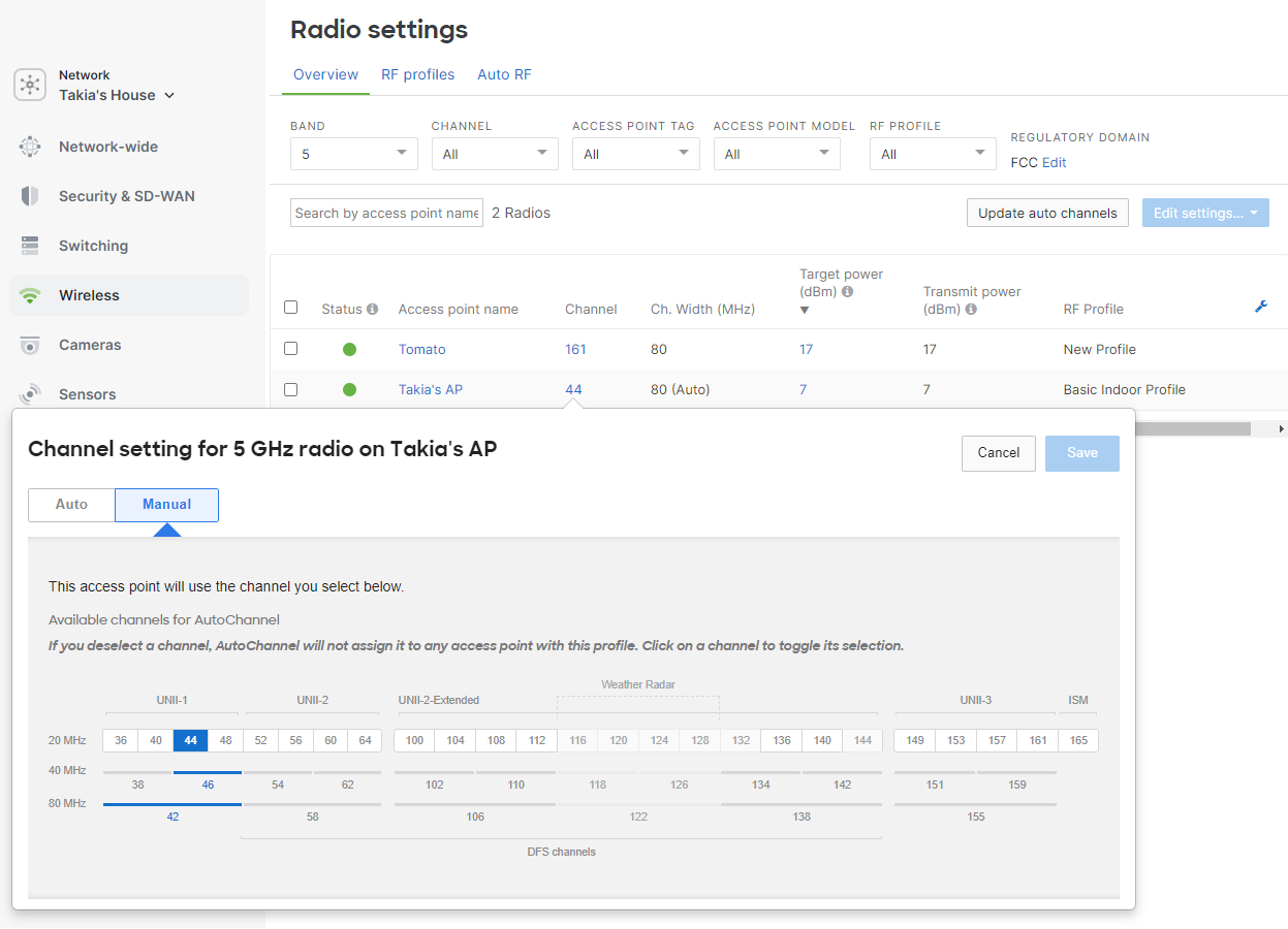
Exclude Dynamic Frequency Selection (DFS)
Some use cases may require that Dynamic Frequency Selection (DFS) channels are excluded from the Auto Channel algorithm. DFS channels can be allowed or excluded on the radio settings page in the dashboard by navigating to Wireless > Radio Settings > Edit Profile > Change channels used by AutoChannel > Deselect DFS Channels.

Since DFS channels can only be used until radar communication is heard, disabling DFS may be useful if the wireless network is in close proximity to a harbor, airport, or weather radar station. Administrators may also want to disable DFS if most local wireless clients do not support DFS channels.
Many helicopters have radar systems that can trigger DFS events on wireless networks which would result in channel changes. Hospitals and other mission-critical locations that may have a helipad should consider excluding DFS channels. When a DFS event occurs, all the APs in a network will switch to the next best channel (disconnecting all clients on DFS channels) as per regulation requirements, which would be a non-DFS channel and then a DFS channel.
Radio Channel Width
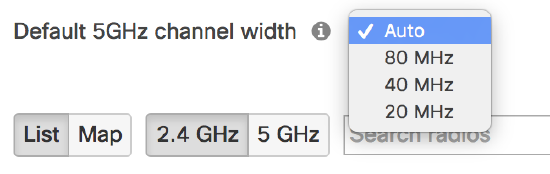
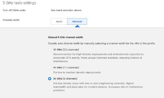
The dashboard offers the ability to set a default channel width, which will be factored into the Auto Channel algorithm for 5 GHz. This can be left at auto width which will adjust the width of the 5 GHz radio based on the Auto Channel algorithms discussed below. A default setting of 80 MHz width can be configured to allow for optimal wireless throughput. However, using an 80 MHz width may cause more co-channel contention. The setting can be reduced to 40 or 20 MHz to reduce channel overlap in high-density deployments. The default channel width can be specified on the radio settings page in the dashboard under the drop-down if using the old view page and within the RF profile settings if viewing the new dashboard page. The width may be set differently on a per-AP basis, either using the overrides by selecting an AP or by opting to use Auto.
The Auto TX algorithm will never set the transmit power below 2 dBm for 2.4 GHz and 5 GHz radios.
Cisco Meraki APs that do not support 80 MHz-wide channels will default to 40 MHz for their channel width.
Auto Channel width is the default setting on firmware MR 25.1 and higher. Upon upgrading to MR 25.1, Auto will be selected if a bandwidth setting had not previously been made.
Real-Time Auto Channel
Newer Cisco Meraki APs with a dedicated scanning radio are able to use the real-time Auto Channel algorithm. Since these APs have full visibility into RF conditions on all channels, the AP and the dashboard are able to make fast channel-planning decisions in high-density RF environments.
RF Metrics
Cisco Meraki APs are constantly collecting information from the RF environment; the dedicated scanning radio continually monitors on all channels for Air Marshal and RF. The table below outlines in detail the metrics that are collected by each AP and analyzed by the cloud controller for the real-time Auto Channel algorithm:
| Metric | Description |
| Usage demand | Some APs handle a greater load than other APs in the same network. APs within the dashboard network are monitored for their usage demand. Client count and traffic are calculated to weigh the "value" of one AP vs. another. This metric helps ensure the cleanest channels are used in the most demanding areas. |
| Airtime availability |
Every access point measures contention and airtime availability for each channel and bandwidth combination. This metric maximizes available airtime for the BSS, which also minimizes contention and improves performance and roaming. Meraki APs registered within the dashboard and out-of-network APs are considered in this metric. Meraki APs within the dashboard network are weighed higher to optimize roaming and airtime usage distribution. Rather than just counting and considering the number of overlapping networks, this metric ensures that the AP will coexist on a channel and have ample airtime availability. |
| Channel utilization | Channel utilization includes both 802.11 and non-802.11 sources. External sources of interference like microwaves and DAS systems are detected by this metric and can be seen on the RF spectrum page. |
*A BSSID is a unique identifier for each 802.11 access point and is made up of the radio's MAC address. Each SSID that an AP transmits has a different BSSID and in most cases a unique virtual MAC is used that is based on the hard-coded radio MAC. BSSIDs are discovered by the Meraki access point by both passive scanning and active probing on each channel.
Channel adjustments are made by the dashboard using information reported by the deployed APs. The dashboard will instruct an AP to change to a different channel for a number of reasons, such as when a new AP is added, the "Update Auto Channels" button is pressed, the radio channels get jammed, during the steady-state process, and during channel switch announcements. The APs in a network will use the information they have gathered from the environment and will calculate to see if there are any channels that have better performance. If an AP determines there are better channels, the AP will switch to it when the Auto Channels update every 15 minutes.
Channel Changes
Channel adjustments are made by the dashboard using information reported by the deployed APs. The dashboard will instruct an AP to change to a different channel for a number of reasons, outlined below:
New AP added
The dashboard will automatically adjust the channel on a new AP to a channel that is best optimized for the location where the AP is installed. The dashboard will collect information from the newly added AP and will select the channel that best fits within the existing wireless network.
Adding a new AP will not cause neighboring APs to change channels immediately. Neighboring APs will adjust their channels based on the other reasons outlined below.
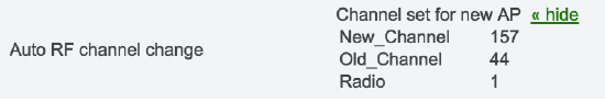
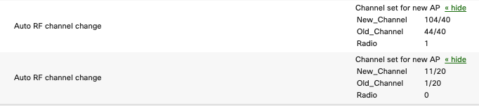
Logging
The event log will report this type of channel change as "Channel set for new AP," and the API will return reason value 1. This event will include the radio number, old channel, and new channel. Below is an example of one of these events:
Update Auto Channels Button
Pressing the Update Auto Channels button on the radio settings page in the dashboard will force a one-time optimization of channels used by all APs within the dashboard network. This will usually result in a minute or two of downtime as the APs adjust their channel.
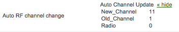
Logging
The event log will report this type of channel change as "Auto Channel Update," and the API will return reason value 2. The event will include the radio number, old channel, and new channel. Below is an example of one of these events:
Jammed Channel
A new source of interference can cause a channel to become unusable. If one of the AP's radios becomes unusable for clients due to interference, the dashboard will instruct the AP to change to another channel with better RF metrics as outlined above.
The dashboard detects a jammed channel by analyzing utilization. If the non-802.11 utilization on one of the client-serving radios is 65% or greater for one minute, the dashboard will instruct the AP to change to a different channel. The utilization that is analyzed is non-802.11 interference that would be transmitted by a microwave or wireless video camera.
Clients that are on the AP during the channel switch will be instructed to move with the AP to a new channel via a channel switch announcement (CSA) which will maintain their connection. Clients that do not hear the CSA over the interference will reassociate with an AP (either the original AP or roam to another one).
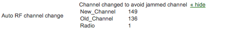
Logging
The event log will report this type of channel change as "Channel changed to avoid jammed channel," and the API will return reason value 3. This event will include the radio number, old channel, and new channel. Below is an example of one of these events:
Steady State
The most common reason for a channel change is the steady state process. The cloud controller runs this process every 15 minutes. If there is a channel with a better metric when the steady state process runs, the AP will be instructed to change its channel.
Client Awareness
The steady state algorithm is client-aware. Auto RF will take into consideration metrics around channel utilization, channel width, associated devices, and traffic load for the 2.4 and 5 GHz radios of every AP in a network when determining optimal channel assignment for the APs in the network.
Channel Switch Announcements
APs will use channel switch announcements to move clients from one 20 Mhz or 40 Mhz channel to another. Our tests have found that moving from one 80 Mhz channel to another can cause interruptions, and thus we do not change from an 80 Mhz channel if clients are connected. Since many clients do not support CSA on the 2.4 GHz spectrum, those channels will not be considered for channel change via steady state if a client is associated.
CSA for Auto Channel is available on MR 25+ firmware, and the feature can be enabled by ensuring you have at least MR 25 using the Organization > Firmware Upgrades page.
Mesh Awareness
The steady state algorithm is mesh aware and will not adjust the channel of an AP's radio that is serving mesh repeaters. Radios on an AP that are acting as a gateway for an active mesh repeater will not change channels. The process of a radio changing its channel results in a few seconds of downtime, and dropping a mesh link could result in packet loss. The AP's radio will resume steady stage changes if the mesh topology recalculates the route or will change its channel as a result of one of other reasons discussed in this document.
DFS Awareness
Changing to a DFS channel requires a channel availability check (CAC) back-off which prevents client transmissions for 60 seconds. While clients are connected, only non-DFS channels are considered. However, once clients disconnect from the AP, a DFS channel may be reconsidered.
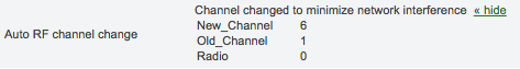
Logging
The event log will report this type of channel change as "Channel changed to minimize network interference," and the API will return reason value 4. This type of event will include the radio number, old channel, and new channel. Below is an example of one of these reports:
Opportunistic Auto Channel
Cisco Meraki APs that do not have a dedicated third radio (or APs with a third radio disabled due to power restrictions) will use the opportunistic Auto Channel algorithm. This algorithm uses similar metrics to the real-time Auto Channel covered above. The data is collected every two hours via opportunistic scanning and will scan off-channel if clients are not connected. Because information is collected over a longer time period and there is limited real-time visibility to other channels, the frequency of channel changes is much more conservative.
Channel Changes
Channel changes are more conservative/less frequent because the AP needs to make more assumptions on the channel quality when comparing it to the real-time algorithm. There are three main cases in which a channel will be changed with the opportunistic Auto Channel:
- New AP added
- Steady state
- Update Auto Channel button
Steady state channel changes will only occur at night or during periods of low network usage. Administrators are able to force a scan with the opportunistic Auto Channel algorithm by pressing the Update Auto Channel button on the radio settings page in the dashboard.
Auto TX
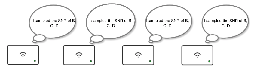
Each AP samples the signal-to-noise ratio (SNR) of neighboring APs that reside in the same dashboard network. All radios on an AP can perform the sampling. The SNR readings are compiled into neighbor reports which are sent to the cloud for processing. The cloud aggregates neighbor reports from each AP. Using the aggregated data, the cloud can determine each AP's direct neighbors (neighbors that a client might directly roam too) and how much each AP should adjust radio transmit power so coverage cells are optimized. Once calculations are complete, the cloud instructs each AP to decrease (or in some instances increase) transmit power to reach an optimal power level. The Auto TX process is performed every 20 minutes for each AP in the dashboard network on both 2.4 GHz and 5 GHz radios.
Real-Time Auto TX Process
This example demonstrates the process, with a dashboard network containing four APs with overlapping coverage.
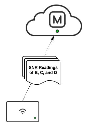
- Each AP will sample the SNR of its neighbors and compile the readings into a neighbor report to be sent to the cloud.
- The cloud requests the neighbor report from each AP in the dashboard network.
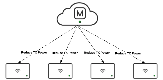
- Once the cloud has the reports from each AP, it aggregates them and determines each AP's direct neighbor(s) and how much each AP should adjust their transmit power to achieve optimal coverage overlap. If necessary, the Auto TX algorithm will lower the transmit power of each AP within a range of 1 dB - 3 dB or increase the transmit power 1 dB per iteration. The target is 30 dB SNR for an AP's strongest direct neighbor, but never less than 17 dB SNR for an AP's weakest direct neighbor. Reducing transmit power too much with weak neighbors present could cause a hole in coverage.
- Once transmit power levels have been calculated, the cloud iterates through each AP in the dashboard network, instructing them to decrease or increase their transmit power. If the target SNR is already met, no transmit power adjustment is needed.
- This process is repeated every 20 minutes on each AP in the dashboard network.
Opportunistic Auto TX
The Auto TX algorithm is available only to devices with a third radio (Ex. MR18, MR34, etc.). Other devices will use the opportunistic Auto TX algorithm. This algorithm uses a different metric set to determine the appropriate power level, given that the AP does not have real-time visibility of neighboring APs. Because information is collected over a longer time period and there is limited visibility to other APs, the resulting power level may be higher than optimal.
Mesh Awareness
The steady state algorithm is mesh aware and will not adjust the power of a AP's radio that is serving mesh repeaters. Radios on an AP that are acting as a gateway for an active mesh repeater will not change transmit power.
Determining Auto TX Effectiveness
It is possible to determine if the Auto TX algorithm has adjusted the transmit power of APs by looking at the transmit power values on the Radio Settings page. If an adjustment has been made, an AP's radio will show the current transmit power in the form of X dBm(Auto). In order to determine the effect Auto TX is having on the wireless network, a baseline site survey needs to be compared to a site survey taken after Auto TX is enabled. Prior to enabling Auto TX, take a site survey of the entire wireless network. Once Auto TX is enabled, wait 24 hours and perform another site survey. Compare the signal strength, coverage areas, and channel overlap of both surveys to determine the effect Auto TX makes on the wireless environment.
Band Steering
Dual-band operation with band steering detects clients capable of 5 GHz operation and steers them to that frequency, which leaves the more crowded 2.4 GHz band available for legacy clients. This helps improve end-user experience by reducing channel utilization, especially in high-density environments. Dual-band operation with band steering is configured on a per-SSID basis.
DFS Awareness
Changing to a DFS channel requires a CAC back-off, which prevents client transmissions for 60 seconds. While clients are connected, only non-DFS channels are considered. However, once clients disconnect from the AP, a DFS channel may be reconsidered.
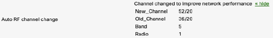
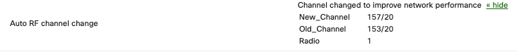
Logging
The event log will report this type of channel change as "Channel changed to improve network performance," and the API will return reason value 6. This type of event will include the radio number, old channel, and new channel. Below is an example of one of these reports:
Reporting
The dashboard will report when Auto RF changes the channel of an access point in the event log, and will show the current status on the radio settings page.
RF Spectrum Page Values
The information on the RF Spectrum Page Overview (Wireless > Monitor > RF Spectrum) is sourced from the scanning radio. The scanning radio on the Meraki AP has a counter for each channel it scans. Each channel is scanned for 150 ms and the counter is updated every 20 nsec. Counters indicate how many times the AP was transmitting, receiving, and saw congestion, as well as the total cycle count. For every 150 ms sample, the AP reads the counters and computes the difference between the value from 150 ms ago and the new value. This difference is used to calculate channel utilization.
The values that an average utilization channel can take falls in one of the following ranges:
- Very low (< 10%)
- Low (10-30%)
- Fair (30-50%)
- High (50-70%)
- Very high (70-90%)
- Jammed (> 90%)
Event Log
Using the event log's built-in filtering, you can filter only Auto RF events and drill down to a particular access point. The different types of log messages are outlined above.
Radio Number:
- "0" for 2.4 Ghz radio
- "1" for the 5 Ghz radio
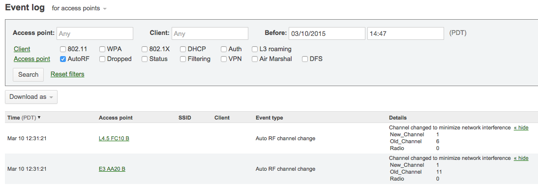
This event log message is shown below when an AP is introduced into a network for the first time.
This event log message below is shown periodically when the AP changes the channel to improve network performance.
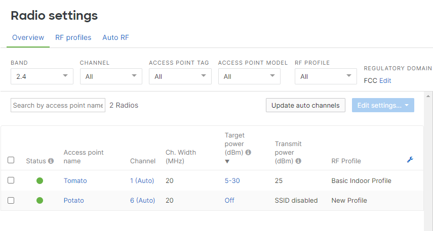
Radio Settings Page
The radio settings page (Wireless > Configure > Radio Settings) will show the current status of Auto Channel via both a map view and a list view.
List View
The list view will report the current operating channel for each AP. An administrator can toggle between 2.4 Ghz, 5 Ghz and 6 Ghz to change which radio is being reported within the list. (Auto) appearing next to the reported channel indicates that the AP is participating Auto Channel.
Auto TX (transmit) power is part of the Cisco Meraki Auto RF feature set which is designed to provide zero-touch optimization of wireless networks for high-density environments. Specifically, Auto TX leverages the Cisco Meraki cloud to manage radio transmit power on APs in order to optimize coverage cells for roaming. As the wireless environment changes, radios on the AP's can adapt accordingly without the need for an on-site wireless controller.