
MV21 Installation Guide
MV21 Overview
The Cisco Meraki MV21 is a networked camera that is exceptionally simple to deploy and configure due to its integration into the Meraki dashboard and the use of cloud augmented edge storage. The MV family eliminates the complex and costly servers and video recorders required by traditional solutions which removes the limitations typically placed on video surveillance deployments.
Package Contents
In addition to the MV camera, the following are provided:

Ethernet Port
The MV21 features a 100BASE-TX Ethernet port that supports 802.3af PoE.
Pre-Install Preparation
You should complete the following steps before going on-site to perform an installation.
Configure Your Network in Dashboard
The following is a brief overview only of the steps required to add an MV21 to your network. For detailed instructions about creating, configuring and managing Meraki Camera networks, refer to the online documentation (https://documentation.meraki.com/MV).
- Login to http://dashboard.meraki.com. If this is your first time, create a new account.
- Find the network to which you plan to add your cameras or create a new network.
- Add your cameras to your network. You will need your Meraki order number (found on your invoice) or the serial number of each camera, which looks like Qxxx-xxxx-xxxx, and is found on the bottom of the unit.
- Verify that you the camera is now listed under Cameras > Monitor > Cameras.
Check and Configure Firewall Settings
If a firewall is in place, it must allow outgoing connections on particular ports to particular IP addresses. The most current list of outbound ports and IP addresses for your particular organization can be found here.
DNS Configuration
Each MV21 will generate a unique domain name to allow for secured direct streaming functionality. These domain names resolve an A record for the private ip address of the camera. Any public recursive DNS server will resolve this domain.
If utilizing an on site DNS server, please whitelist *.devices.meraki.direct or configure a conditional forwarder so that local domains are not appended to *.devices.meraki.direct and that these domain requests are forwarded to Google public DNS.
Assigning IP Addresses
At this time, the MV21 does not support static IP assignment. MV21 units must be added to a subnet that uses DHCP and has available DHCP addresses to operate correctly.
Installation Instructions
Note: Each MV21 comes with an instruction pamphlet within the box. This pamphlet contains detailed step by step guides and images to assist in the physical install of the camera. A pdf of the pamphlet can be found here.
Note: During first time setup, the MV21 will automatically update to the latest stable firmware. Some features may be unavailable until this automatic update is completed. This process may take up to 10 minutes due to enabling of whole disk encryption.
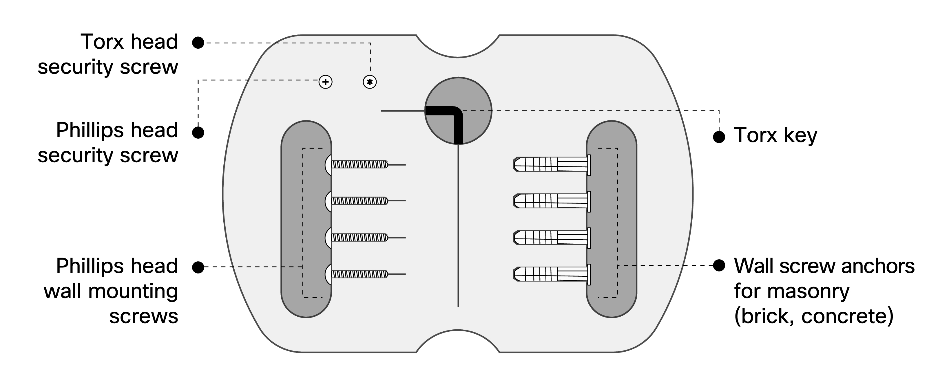
Wall Mounting Instructions
For most mounting scenarios, the MV21 wall mount provides a quick, simple, and flexible means of mounting your device. The installation should be done in a few simple steps:
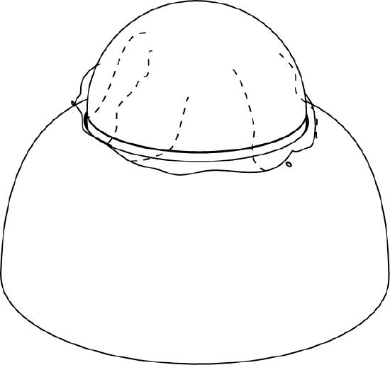
1. Leave protective plastic sticker on camera bubble
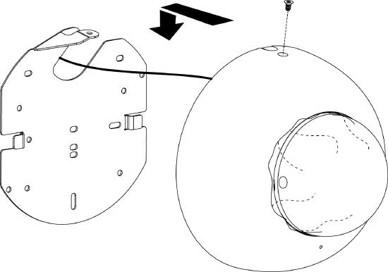
2. Use template to determine mounting hole locations before screwing in the mount plate. Peel backing from mount template to stick on wall. Slide the MV21 onto the wall mount.
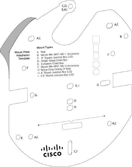
3. Screw the mounting plate onto the wall in pre-determined locations. Use template holes marked with the letter “A” for standard wall mounting.
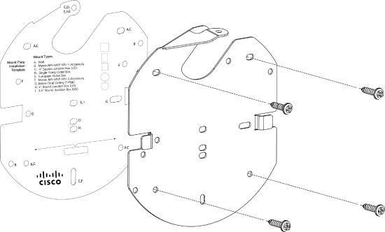
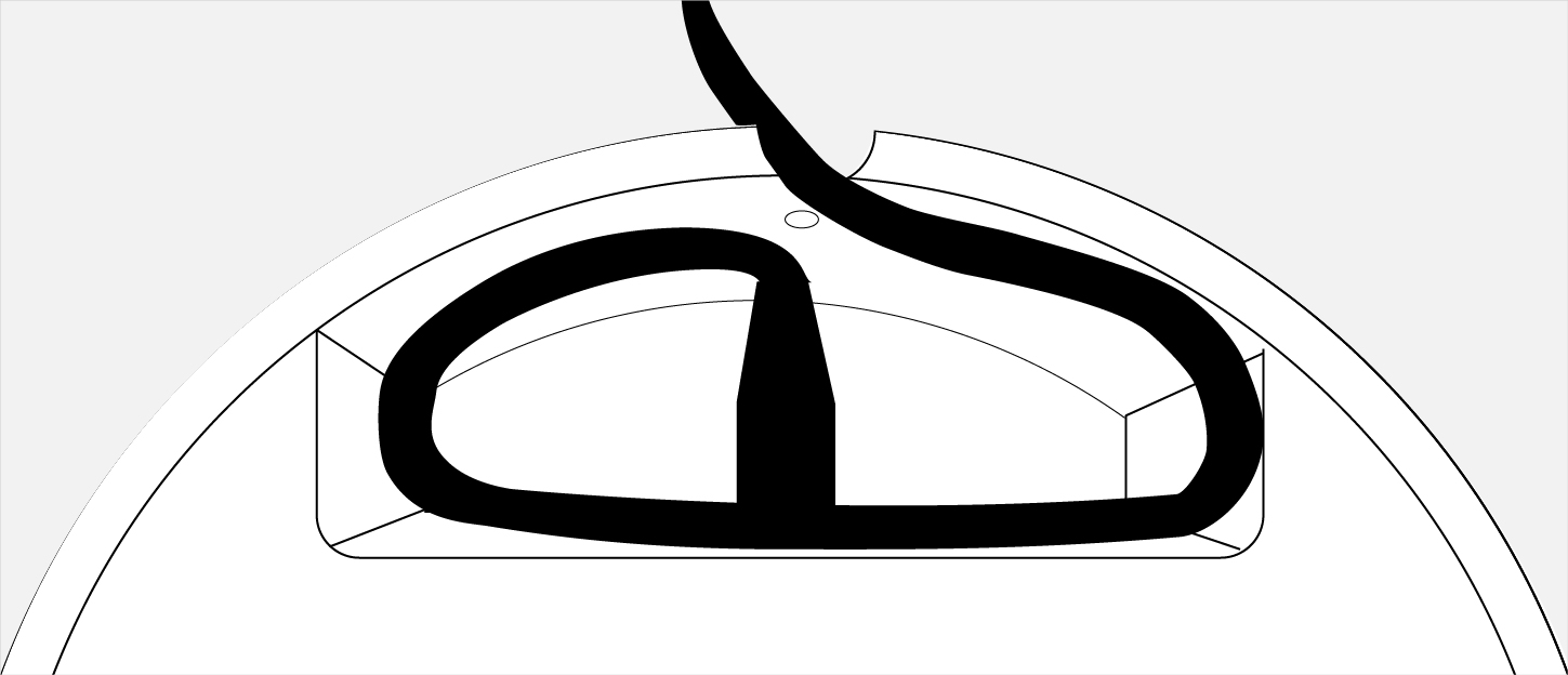
4. Connect PoE cable to camera. For cords that will exit the top of the camera, loop the cable inside the camera as shown.
5. Slide camera over top of mount plate and slide down into mount plate hooks. Secure with Phillips or Torx head safety screw.
 or
or 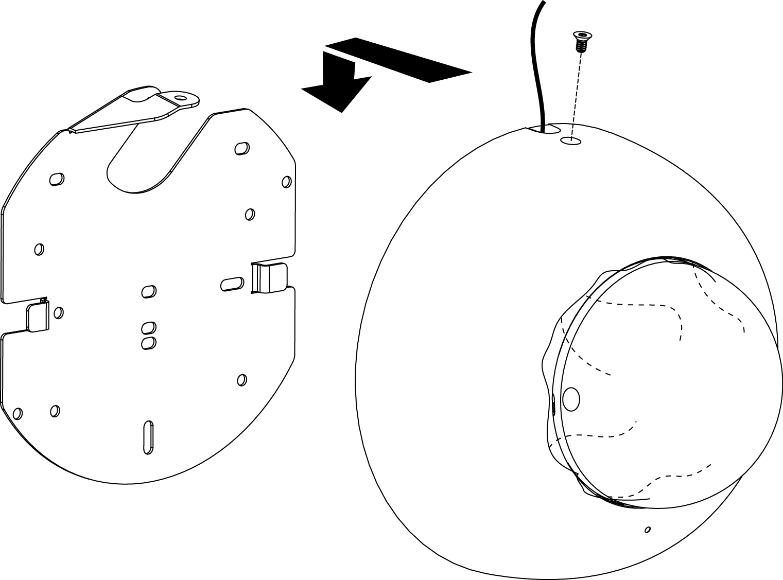
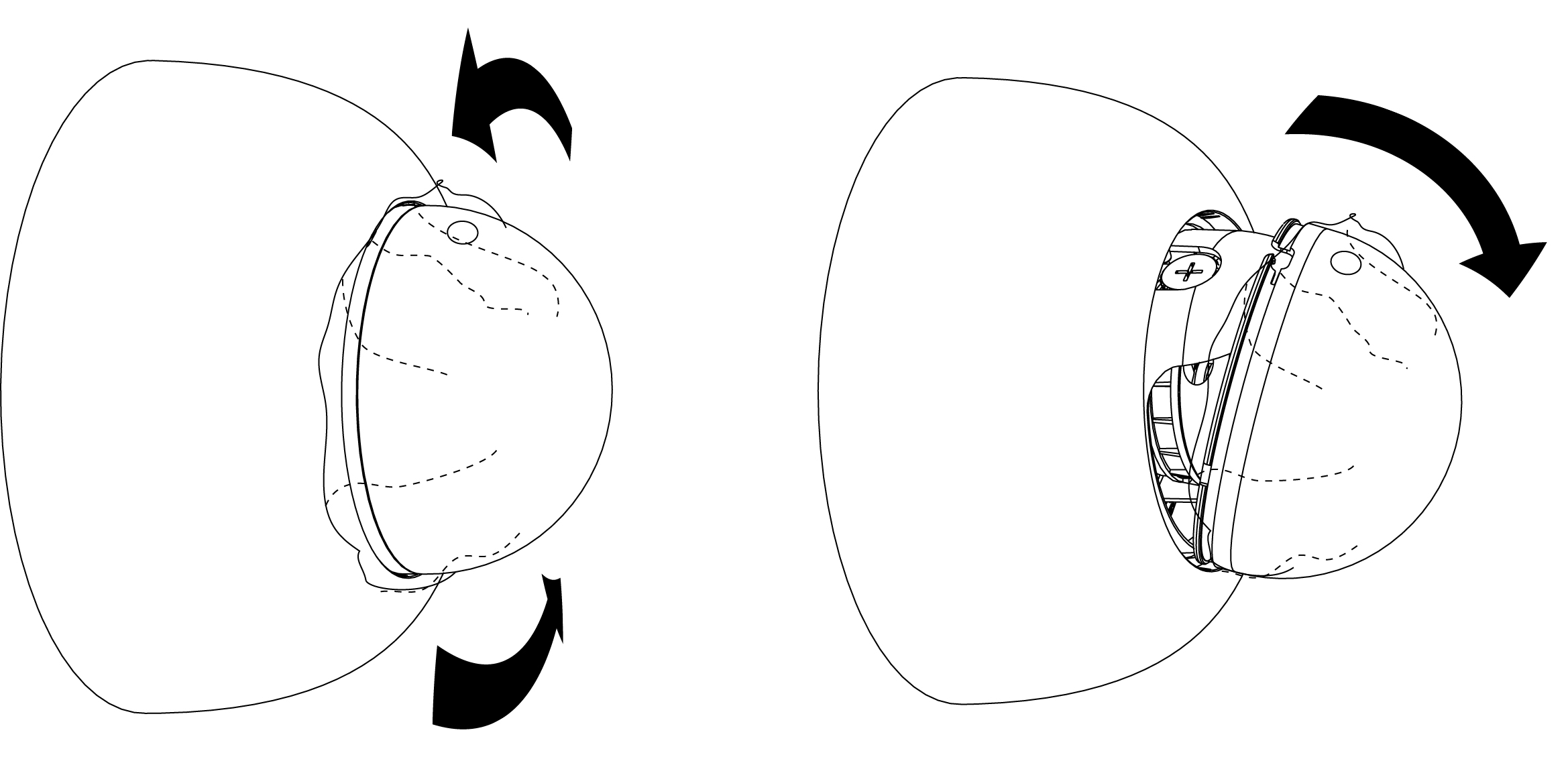
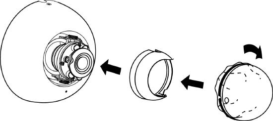
6. Turn bubble counter clockwise to unlock. Hinge bubble off of body to remove.
7. Pinch near thumb screws and pull straight away from the camera to remove lens guard.

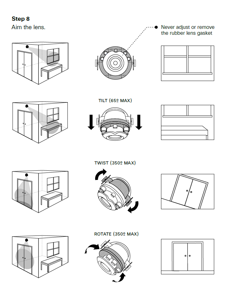
8. Aim the lens. Look through the camera on the Meraki Dashboard to fine tune the picture. The camera sensor and lens unit can be physically tilted through a range of 65 degrees, rotated through a range of 350 degrees, and panned through a range of 350 degrees. The image can only be rotated by 180 degrees in software and no other adjustments can be made. Zoom and focus can be adjusted remotely and can not be adjusted physically on the camera.
Note: Never adjust or remove the rubber lens gasket
9. Replace lens guard and bubble. Turn bubble clockwise to lock.
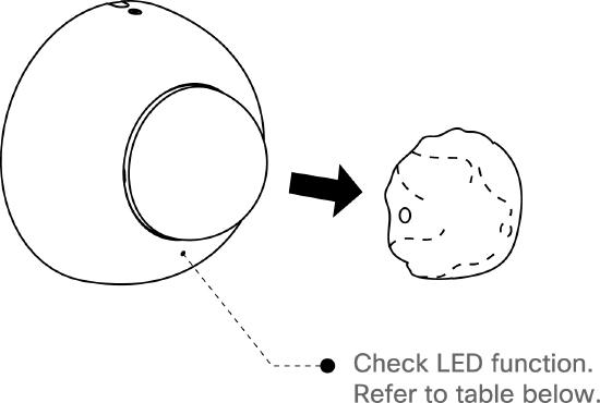
10. Remove protective plastic sticker. Check LED function. Use the Meraki Dashboard to adjust camera focus and configure other settings.
T-rail Mounting Instructions
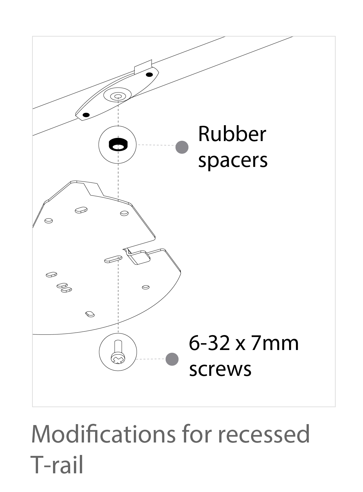
To mount your MV21 on a drop ceiling T-rail, use the included hardware. The hardware can be used to mount to most 9/16”, 15/16”, or 1 ½” T-rails.
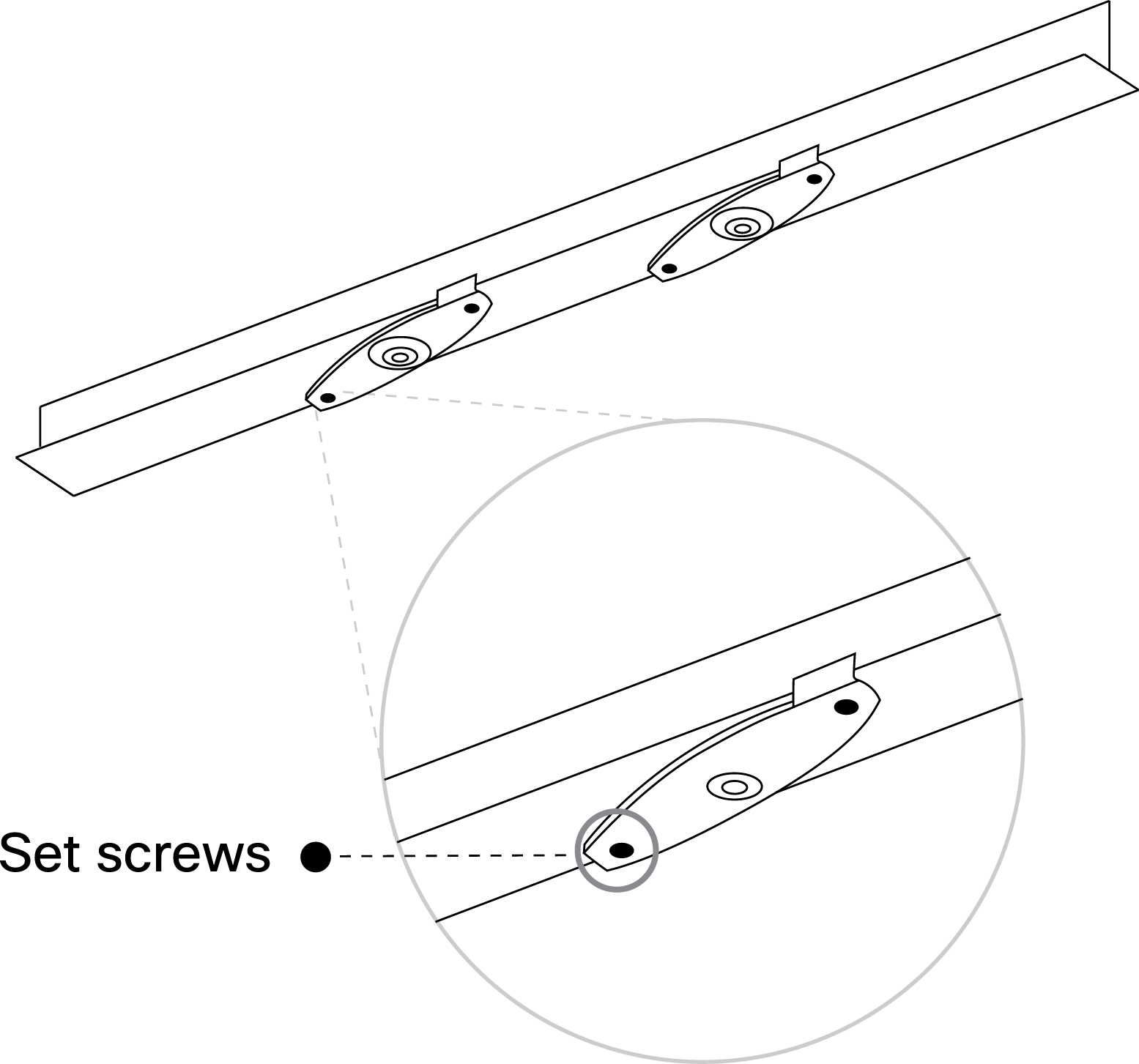
1. Using the dashed lines on the mount plate template as a guide, set the proper spacing of the clips.
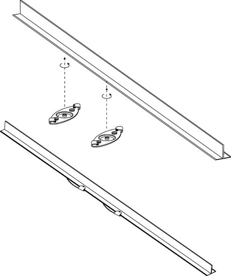
2. Tighten the set screws on the T-rail clips and secure them using a 5/64” (2 mm) hex key.
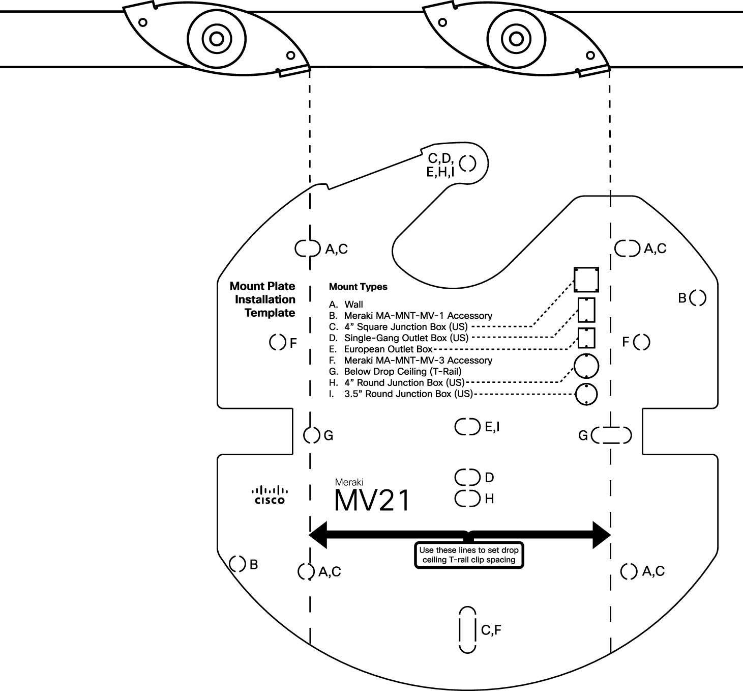
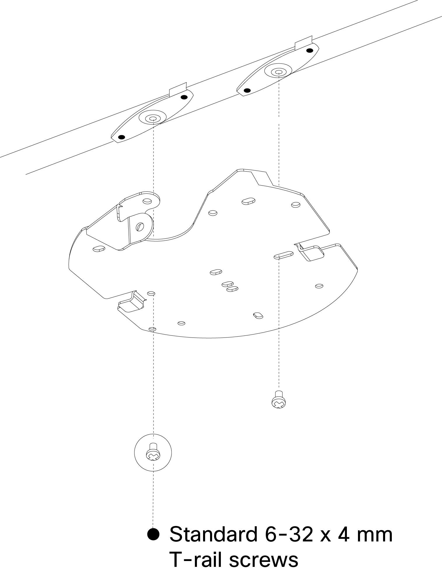
3. Attach the mount plate to the T-rail clips using the mount plate holes (marked with a “G”).
4. Attach the T-rail clips to the T-rail by rotating them and snapping them into place as shown. The black foam pads should be compressed slightly after installation.
Powering the MV21
Remove the cable guard and route the Ethernet cable from an active port on a 802.3af PoE switch or PoE injector.
Note: Power over Ethernet supports a maximum cable length of 300 ft (100 m).
LED Indicator
Your MV21 is equipped with a LED light on the front of the unit to convey information about system functionality and performance:
- Flashing Green (1 second interval) - MV is upgrading or initializing for the first time.
- Flashing Green (3 second interval) - Encrypting disk.
- Solid Green - MV is operating nominally.