MV72 Series Installation Guide
MV72 Series Overview
The Cisco Meraki MV72 series are network cameras that are exceptionally simple to deploy and configure due to its integration into the Meraki Dashboard and the use of cloud augmented edge storage. The MV family eliminates complex and costly servers and video recorders required by traditional solutions which removes the limitations typically placed on video surveillance deployments.
Package Contents
In addition to the MV camera, the following are provided:
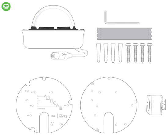
From top-left to bottom-right:
- 1 x MV72
- 1 x T10 Torx key
- 1 x desiccant pack
- 4 x wall anchors
- 4 x wall screws
- 1 x base mount plate
- 1 x base mount wall template
- 1 x conduit adapter
Powering the MV72 Series
The MV72 features a 1000BASE-TX Ethernet port and requires 802.3at PoE minimally for operation. Route the Ethernet cable from an active port on a PoE switch or PoE injector.
Note: Power over Ethernet supports a maximum cable length of 300 ft (100 m).
Pre-Install Preparation
You should complete the following steps before going on-site to perform an installation:
Configure Your Network in Dashboard
The following is a brief overview only of the steps required to add an MV72 series camera to your network. For detailed instructions about creating, configuring and managing Meraki Camera networks, refer to the online documentation (https://documentation.meraki.com/MV).
- Login to http://dashboard.meraki.com. If this is your first time, create a new account.
- Find the network to which you plan to add your cameras or create a new network.
- Add your cameras to your network. You will need your Meraki order number (found on your invoice) or the serial number of each camera, which looks like Qxxx-xxxx-xxxx, and is found on the bottom of the unit.
- Verify that you the camera is now listed under Cameras > Monitor > Cameras.
Check and Configure Firewall Settings
If a firewall is in place, it must allow outgoing connections on particular ports to particular IP addresses. The most current list of outbound ports and IP addresses for your particular organization can be found here.
DNS Configuration
Each camera will generate a unique domain name to allow for secured direct streaming functionality. These domain names resolve an A record for the private IP address of the camera. Any public recursive DNS server will resolve this domain.
If utilizing an on site DNS server, please whitelist *.devices.meraki.direct or configure a conditional forwarder so that local domains are not appended to *.devices.meraki.direct and that these domain requests are forwarded to Google public DNS.
Assigning IP Addresses
At this time, the MV72 series camera does not support static IP assignment. MV72 units must be added to a subnet that uses DHCP and has available DHCP addresses to operate correctly.
Installation Instructions
Note: Each MV72 comes with an instruction pamphlet within the box. This pamphlet contains detailed step by step guides and images to assist in the physical install of the camera.
Note: During first time setup, the MV72 will automatically update to the latest stable firmware. Some features may be unavailable until this automatic update is completed. This process may take up to 5 minutes due to enabling of whole disk encryption.
Mounting Instructions
For most mounting scenarios, the MV72 wall mount provides a quick, simple, and flexible means for mounting your device. The installation should be done in a few simple steps:
Note: Leave protective plastic cover on the optical dome, as this will prevent the optical dome from any damage during installation.
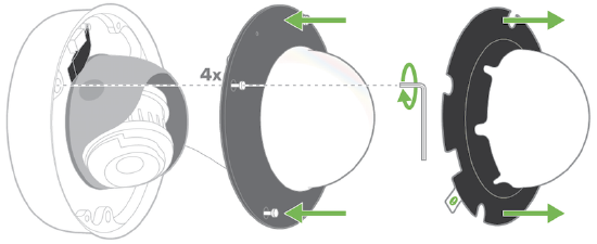
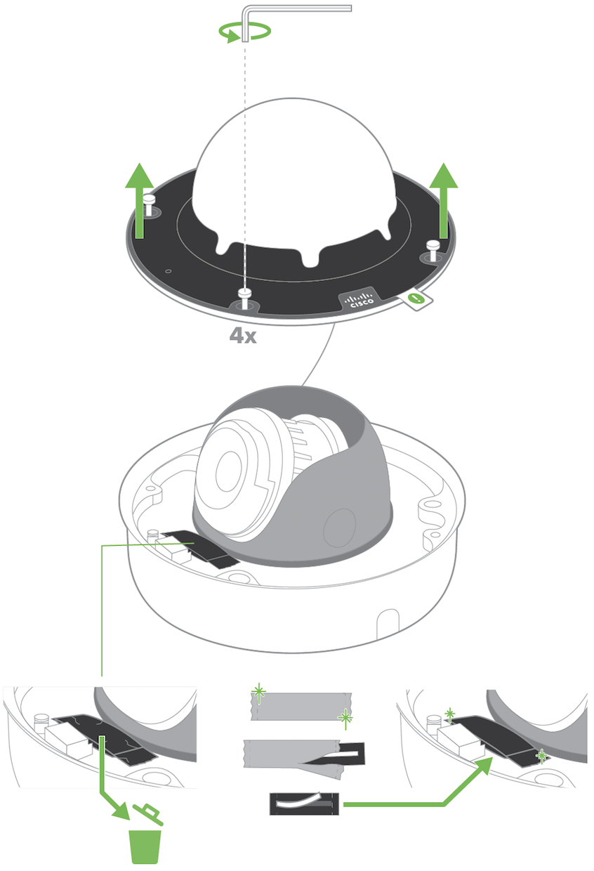
1. Carefully loosen all four Torx head security screws and remove the optical dome from the base. There is a tether cable attached to the optical dome and camera base to simplify installation. Remove the desiccant pack included in the camera during product shipment and replace with the provided spare desiccant pack. This is important to prevent moisture accumulating within the sealed optical dome.
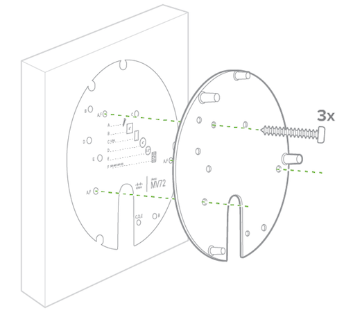
2. If you're mounting to a 4x4 junction box, first route the Ethernet cable through the gap and affix the base mount plate to the junction box.
If wall mounting, use template to determine mounting hole locations before screwing in the base mount plate. Peel backing from mount template to stick on wall. Use template holes marked with the letter “A” for standard wall mounting. Screw the base mount plate onto the wall in pre-determined locations using the provided wall screws.
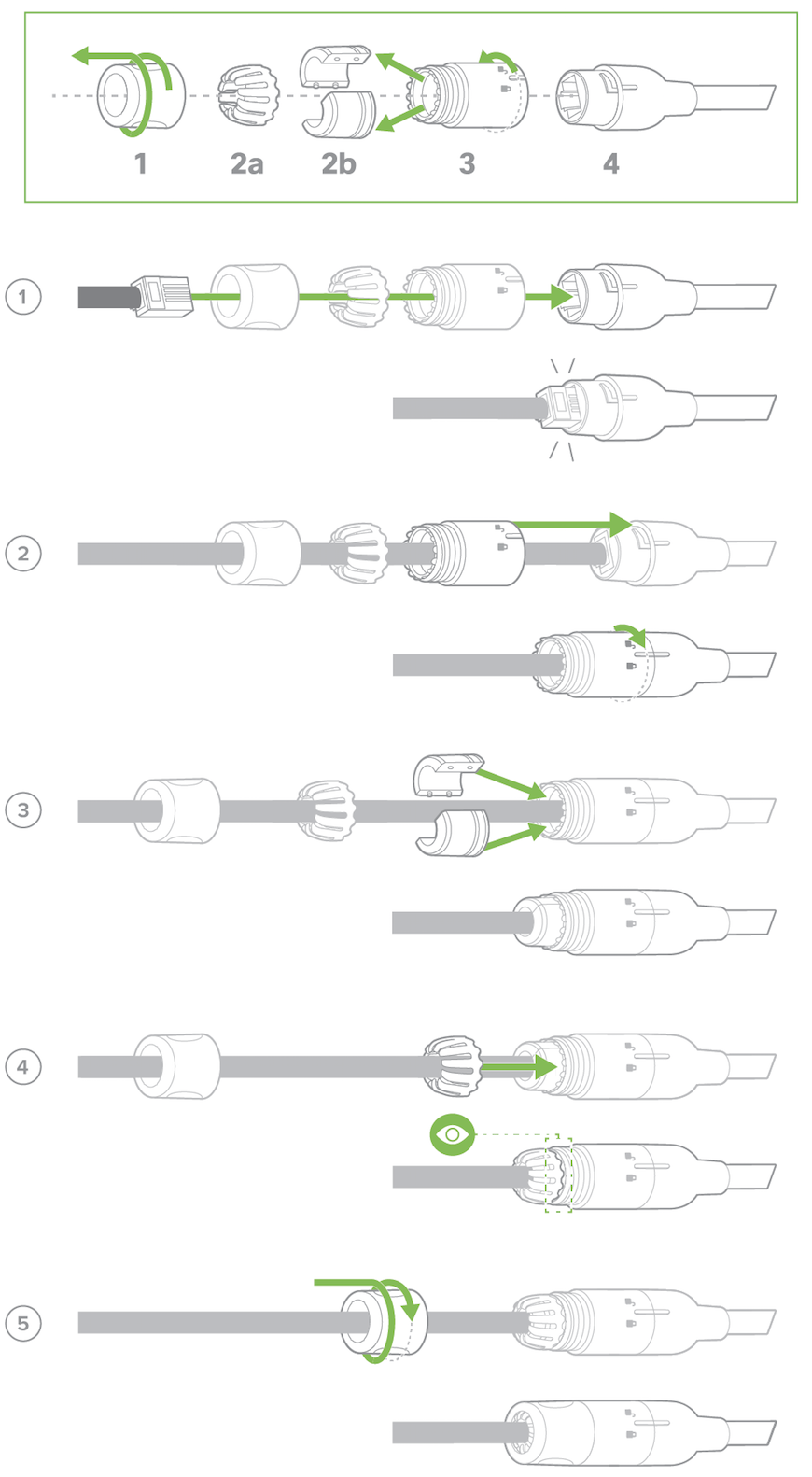
3. Follow this in-depth cable gland assembly guide to connect the PoE cable to the camera cable gland and ensure seal is water-tight. This step is very important and may result in damage to the camera if done improperly.
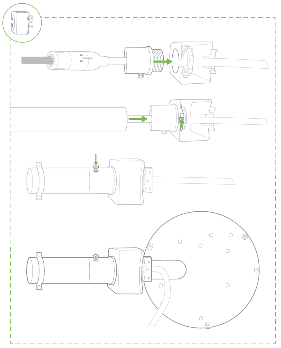
Note: If installing external conduit terminated at the camera, ensure the camera conduit adapter and terminal adapter are pulled over the camera pigtail prior to making the connection!
3a. If using conduit adapter, attach the terminal adapter to the conduit adapter. Route the conduit over the water-tight cable gland assembly and terminate at the terminal adapter. Ensure the camera conduit adapter is securely placed on the base mount plate as pictured.
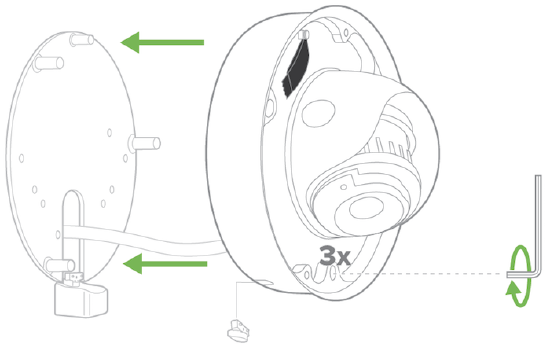
4. Slide camera over top of base mount plate. Secure all three Torx head security screws. Remove the mouse hole cover if using conduit adapter.
5. Observe the status LED on the left side of the camera lens assembly and ensure the camera is connected via Ethernet (solid green) or WiFi (solid blue). A MV must first be provisioned over a wired Ethernet connection before it can be deployed wirelessly. For information on how to connect via WiFi, see the setup guide here.
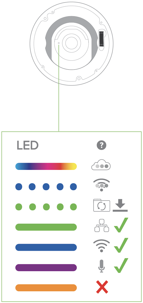
Your MV72 is equipped with a LED light on the front of the unit to convey information about system functionality and performance.
The various status conditions of a MV are indicated by the following colors and patterns:
- Rainbow (solid, rotating through colors) - MV is booting up.
- Flashing Blue - MV is searching for WiFi network(s).
- Flashing Green - MV is upgrading or initializing for the first time.
- Solid Green - MV is connected via Ethernet.
- Solid Blue - MV is connected via WiFi.
- Solid Violet - MV has audio recording enabled.
- Solid Amber - MV is not able to connect to Dashboard.
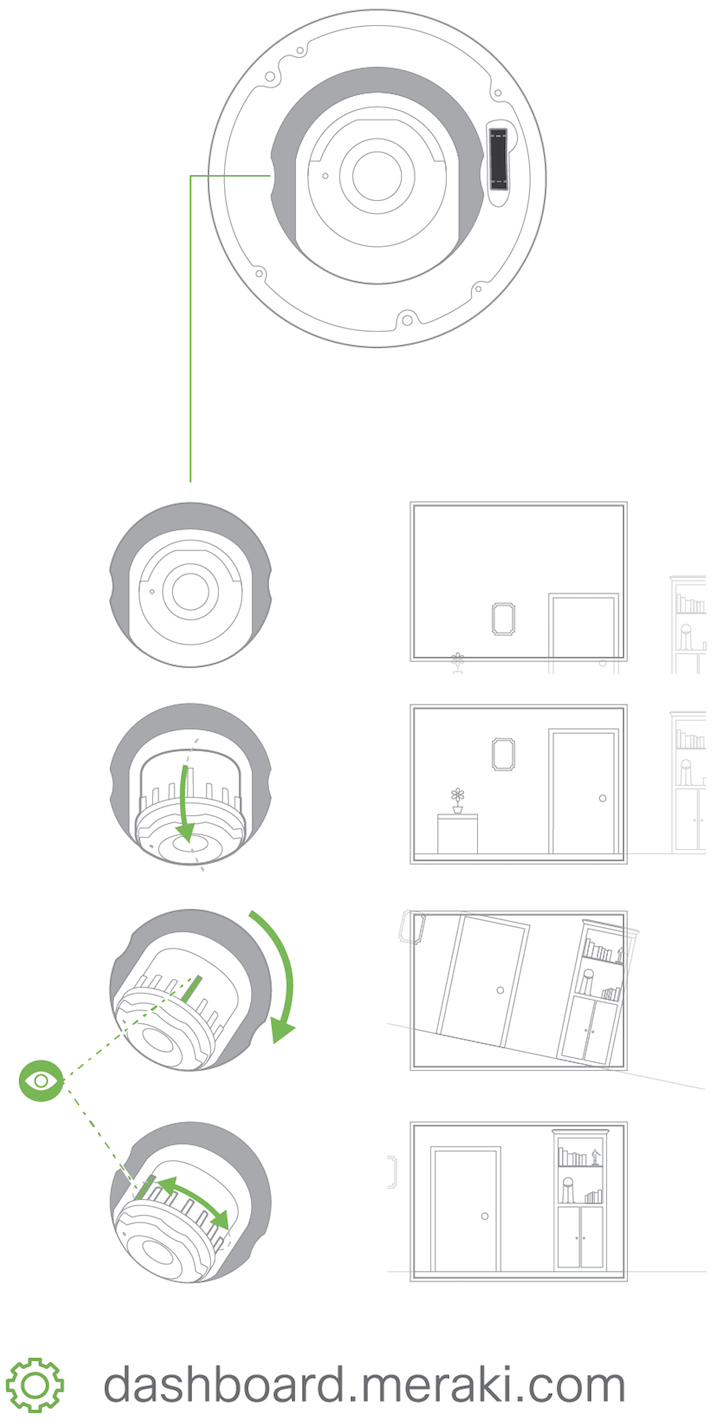
6. Aim the lens. Look through the camera on the Meraki Dashboard to fine tune the picture. The camera sensor and lens unit can be physically tilted through a range of 65 degrees, rotated through a range of +/-90 degrees, and panned through a range of 354 degrees. The image can only be rotated by 180 degrees in software and no other adjustments can be made. Zoom and focus can be adjusted remotely and can not be adjusted physically on the camera. For more information on zooming, refer to the adjusting the Field of View article.
Note: Never adjust or remove the rubber lens gasket or protective lens guard.
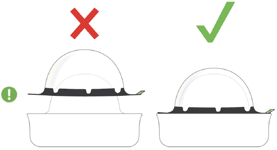
7. Replace optical dome and completely secure all four Torx head security screws. Remove the protective plastic cover.