
WAN behavior on MX75/85/95/105
Overview
This document defines the interface behaviors for MX75/85/95/105 models. The MX firmware has the capability to only have 2 active interfaces. The core behavior outlined here explains how there can be only two active usable WAN uplinks while remaining WAN interfaces are disabled by firmware.
Two Active WAN Uplinks
The current firmware only supports a maximum of two active WAN interfaces. While USB cellular modem is considered a 3rd backup interface, it is not limited by this behavior. A supported configuration of two active uplinks and a third USB cellular modem is supported. When an MX has two active wired connections, the cellular will not be used. Until both WAN interfaces are considered in a down state, cellular will not be active. More information can be found on the 3G/4G Cellular Failover with USB Modems article.
Physical Interfaces
| MX75 | MX85 | MX95 | MX105 | |
| Number of WAN interfaces | 3 (1x SFP and 2x 1Gig RJ45) | 4 (2x SFP and 2x 1Gig RJ45) | 4 (2x SFP+ and 2x mGig RJ45) | 4 (2x SFP+ and 2x mGig RJ45) |
MX75
The MX75 model is a desktop form factor. The interfaces here are similar to the existing MX68/C/W desktop model that has two dedicated WAN interfaces. The following section will outline the behavior for the MX75.
Below is a picture of the 3 physical interfaces available as WAN interfaces for the MX75.
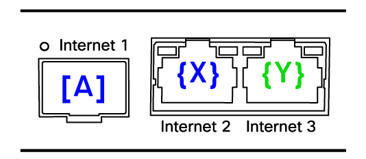
On MX75 the {X} and {Y} interfaces are labeled Internet 2 and 3 respectively.
For the logic, assume the [A]+{X} blue interfaces are a pair and the RJ45 {Y} interface is standalone. RJ45 {Y} has no partner interface.
-
If SFP [A] is used, RJ45 {X} will be disabled. The firmware will allow the use of SFP [A] and RJ45 {Y} only.
-
If both RJ45 {X} and RJ45 {Y} are used then SFP [A] is disabled.
MX85/95/105
Below is a picture of an MX85 4 physical interfaces available. The logic described here applies to the MX85/95/105.
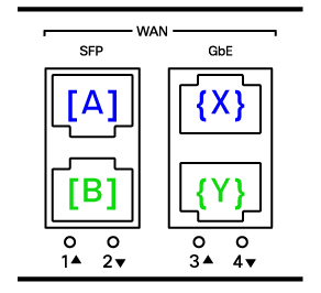
Note: PoE+ on GbE Port 4 (RJ45 “{Y}”). The MX95/105 have 2.5Gbps mGig ports.
Port mappings in this scenario are interfaces 1 through 4. Where interfaces 1 and 2 are SFP interfaces [A] and [B] respectively. And interfaces 3 and 4 are represented by {X} and {Y} respectively.
For the logic, assume the top [A]+{X} blue pair and bottom [B]+{Y} green pair are two sets of interfaces and they are linked together. To clarify, each pair of interfaces will have a partner.
- If SFP [A] is used, RJ45 {X} is disabled. Likewise, if SFP [B] is used RJ45 {Y} is disabled.
- If both RJ45 {X} and RJ45 {Y} are used then both SFP [A] and SFP [B] are disabled, and vice versa will be true if both SFPs are used.
- If SFP [A] and RJ45 {Y} are used then SFP [B] and RJ45 {X} are disabled.
- This particular configuration gives users the ability to have a SFP interface for WAN 1 and RJ45 interface for WAN 2.
- This configuration also accounts for the PoE+ feature on RJ45 {Y} on MX85/95/105. The PoE+ feature can be used to power MG cellular gateway devices as an uplink.
Truth Tables
The following tables summarize the behaviors described in the previous section. The presence of the SFP physical module in the port (inserted all the way) determines if the value is “NO” or “YES”, where the acknowledgement of a physical SFP module is “YES” and vice versa. For the port state, the interface would then be enabled or disabled by the firmware.
The truth tables are applied as part of interface selection while the device is initializing. If a different interface needs to be used then the MX must be rebooted after making the desired physical changes.
Truth Table for MX75
| Module Presence | Port State (MX75) | ||
|
SFP1 [A] |
SFP1 [A] |
RJ45 {X} |
RJ45 {Y} |
|
No |
Disabled |
Enabled |
Enabled |
|
Yes |
Enabled |
Disabled |
Enabled |
Truth Table for MX85/95/105
|
Module Presence |
Port State (MX85/95/105) |
||||
|
SFP1 [A] |
SFP2 [B] |
SFP1 [A] |
SFP2 [B] |
RJ45 {X} |
RJ45 {Y} |
|
NO |
NO |
Disabled |
Disabled |
Enabled |
Enabled |
|
NO |
YES |
Disabled |
Enabled |
Enabled |
Disabled |
|
YES |
NO |
Enabled |
Disabled |
Disabled |
Enabled |
|
YES |
YES |
Enabled |
Enabled |
Disabled |
Disabled |
Interface Selection
This section outlines the behavior for an interface pair. It identifies which interface to prioritize, how it should be detected, when it should be detected, and why the behavior follows this logic.
1. SFP interface prioritization
In an interface pair the SFP interface is prioritized over the RJ45 interface. The MX when deciding which partner interfaces to use in a pair will prefer the SFP interface over the RJ45 interface. If an SFP module is inserted into the MX, the MX will use the SFP interface and disable the partner RJ45 WAN interface.
2. Detection of SFP module
If no physical SFP modules have been detected to be inserted into the MX, then the MX will assume that the preference is to use the RJ45 interfaces. In the case of a failed SFP module, the MX will detect if a module is physically inserted into the SFP interface slot and attempt to use the failed module.
3. Timing of interface decision
Detection of interface selection is done when the device is initializing. This takes place during boot up. If the preference is to use the SFP interfaces, then the SFP module must be inserted when the device is powered off. Please ensure your modules are properly inserted into the MX before boot up.
Once the MX is in a fully initialized state with the SFP module, hot swapping of the module is allowed. The MX will retain preference of the interface while in operation. SFP modules can be removed and another module can be inserted in the same interface without issues. Physically removing an SFP module during operation will not cause the MX to start using the RJ45 interface partner.
4. Two active WAN interfaces
The MX is capable of only two active WAN interfaces, if a partner interface is in a disabled state then it will not be initialized at any point in a WAN failover event. WAN failover between two active interfaces is supported. (e.g. SD-WAN, or SD-Internet)
Disabled partner interfaces will stay disabled unless the conditions upon which they were disabled are changed.
For example, to switch from the SFP interface to the RJ45 partner interface you must reinitialize (reboot) the MX after physically removing the SFP module and populating the RJ45 interface. The recommended method for physical reconfiguration of the WAN interfaces should be done when the MX is powered off.
LED Behavior
The following section describes the LED behavior of interfaces on the MX. This is applicable to both WAN and LAN ports.
SFP Module Port LEDs
In the table below are the LED states.
|
Behavior |
LED |
Description |
|
No operation |
Off |
No module detected, port is not used |
|
Module inserted with cable connected and operational |
Solid amber |
Downshifted speed on 10Gbps SFP+ port. Meaning the port is working at less than 10Gbps speed. Only for MX95/105 |
|
Module operational |
Solid green |
10/100/1000 Mbps with 1 Gbps on copper SFP for MX75/85 1 Gbps on any SFP at full speed for MX75/85 10 Gbps with 10 Gbps SFP+ for MX95/105 |
RJ45 LEDs
The table below outlines the RJ45 LED behavior.
|
Behavior |
LED |
Description |
|
No operation |
Off |
No cable detected or connection, port is not used |
|
Slow link |
Solid amber |
10/100 Mbps 1Gbps for MX95/105 |
|
Full speed |
Solid green |
2.5 Gbps for MX95/105 1 Gbps for MX75/85 |
Dashboard and Firmware
The interfaces being used will be reported via the dashboard. The interfaces that are not being used and are disabled are grayed out.
Dashboard currently does not provide any remote toggle to switch between the pairs remotely.
Local Status Page
The Local Status page will show two Internet links. This would represent the 3 ports on MX75 or the 4 ports on MX85/95/105 used for Internet connections.
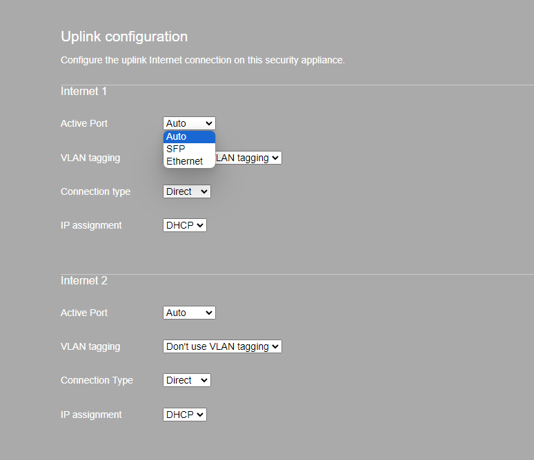
Setting the Active Port under the Local Status Page > Configure will override the default behavior of Auto, forcing the Internet interface to Ethernet, or SFP.