
Auto VPN Hub Deployment Recommendations
About This Document
This document provides recommendations for AutoVPN hub deployments.
These recommendations and the suggested deployment configurations have been collected across the Meraki MX install base (covering hundreds of thousands of AutoVPN sites) and have been vetted by the Meraki MX product team.
While this document provides a high level overview and emphasizes important considerations, please refer to the online documentation for specific details on how to implement the suggested configurations. Meraki’s 24x7 Support is also available to assist as needed.
The Meraki MX AutoVPN technology is versatile and supports many configuration options that are used to address different use cases - many of these are not mentioned here.
This document covers the most popular, common and robust AutoVPN hub deployment options.
Datacenter Hub Deployment
Summary
-
Use a hub and spoke topology.
-
Use OSPF if dynamic routing is required. (an additional router can be used for BGP redistribution)
-
Turn off all non-VPN features. (e.g. Security features, Traffic Analytics)
-
It is always better to re-IP than to use NAT translation of any sort.
Overview
In order to achieve the maximum possible scale for a Meraki AutoVPN deployment, there is really only one topographical choice - Hub and Spoke (H&S). This is due to the large number of tunnels a full mesh solution would incur. The formulae for working out the likely total tunnel count and individual MX tunnel count for both support topologies are as follows:
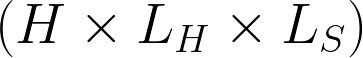
Hub and Spoke - Total Tunnel Count

Where H is the number of hubs, S is the number of spokes, and L is the number of uplinks the MX has (LH for the hubs, LS for the spokes). If each MX has a different number of uplinks, then a sum series, as opposed to a multiplication, will be required.
For example, if all MXs have 2 uplinks (both WAN1 and WAN2 active), and if we have 4 hubs and 100 spokes, then the total number of VPN tunnels in the organization would be 24 + 1600 = 1624.
H = 4, S = 100, LH= 2, and LS = 2
All appliances in this example have two uplinks, so LH = LS = 2. For the hubs, this works out to (4 x (4-1) x 22)/2 = 24. The number of tunnels for all 100 spokes is (4 x 100 x 2 x 2) = 1600.
Hub and Spoke - Hub Tunnel Count

To continue our example, each hub would have a total of 12 tunnels to the other hubs and 400 tunnels to the spokes for a total of 412 tunnels per hub MX.
Hub and Spoke - Spoke Tunnel Count
To complete our example, each MX spoke will have 4 AutoVPN tunnels established to each MX hub for a total of 16 tunnels. That is, each spoke has 4 tunnels to each hub: WAN1-WAN1, WAN1-WAN2, WAN2-WAN1 and WAN2-WAN2, and for four hubs that is 16 tunnels per spoke.
Full Mesh - Total Tunnel Count
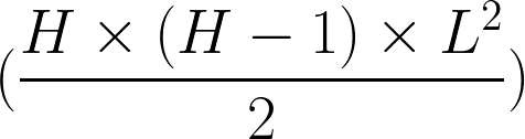
Where H is the number of MXs and L is the number of uplinks each MX has.
For example, if all MXs have 2 uplinks and there are 50 MXs, then the total number of VPN tunnels would be 4900.
Full Mesh - Tunnel Count per MX

To complete the example every MX would have to be able to support 196 tunnels, in this case, we would need around 50 MX100s.
There are, however, multiple ways in which we can architect the H&S network such that we achieve greater flexibility. We will illustrate each of these models below.
Standard Hub & Spoke

How it works
Utilizing the standard Meraki AutoVPN registry to ascertain how the VPN tunnels configured need to form (i.e. via public address space or via private interface address space) as described in Configuring Site-to-site VPN over MPLS.
When should it be used?
Whenever possible is the short answer. It is strongly recommended that this model is the 1st, 2nd and 3rd option when designing the topology. Only if the customer has an exceptionally strong requirement should one of the following H&S derivatives be considered.
Note: AutoVPN hubs should not be added to templates at all. It is not possible to configure an MX as a spoke with exit hub that is part of a template.
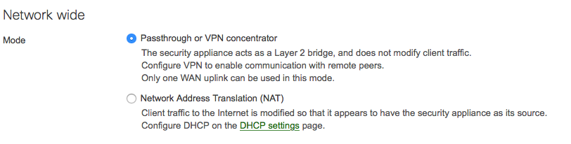
Configuration - VPN Concentrator
Whilst the high-level configuration on a VPN is relatively straightforward, there are a number of potential pitfalls that will be covered here. If more information is required please refer to the definitive guide - VPN Concentrator Deployment Guide.
Global Configuration
It is strongly recommended that all MX AutoVPN hubs are dedicated hubs. As such, the Addressing & VLANs page should look like this:
VPN Configuration
From the Site-to-site VPN page, we need to set the type to Hub (Mesh), as shown below:
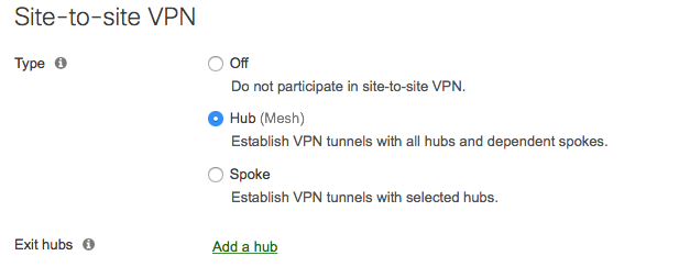
Hub means form a VPN tunnel to everyone who is also a Hub and any spoke that has you configured as a hub. Whereas Spoke means to just VPN to the MXs you have configured as Hubs.
Exit Hub
When an MX is configured as a Hub, then an additional config option becomes available: ‘Exit hub’. This allows you to bind a default route (0/0) to the IPSec security association of that hub in a similar fashion to the ‘Default Route’ option for Spoke MXs.
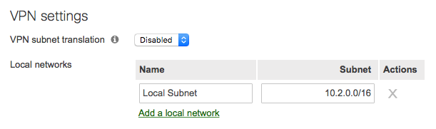
Local Network Advertisement
It should be known that networks that are accessible from the concentrator MX in the data center and need to be advertised to other hubs and/or spokes MXs need to be defined and advertised. As shown below:
In the rare instances that the locally available subnets are not globally unique in the IP schema of the AutoVPN domain, then VPN translation can be enabled such that the entire locally available range can be translated to a unique range, as shown below:
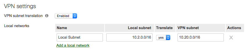
These options are only to be used in emergencies, as the best solution is always to re-IP the offending range such that duplicates do not exist.
Best practice - it is generally recommended to summarize continuous addressing blocks whenever possible (e.g. 10.0.0.0/8).
For reference, below are the RFC1918 private address blocks:
- Class A - 10.0.0.0/8
- Class B - 172.16.0.0/12
- Class C - 192.168.0.0/16
Any additional, more specific subnets contained within these supernets that are available via the advertising hub can/should also be advertised too to affect prioritization among routes. This also extends to non-RFC1918 traffic that is publicly routable that is accessible via the AutoVPN domain.
In the case where more complex routing is needed, please refer to the MX routing behavior document for more information.
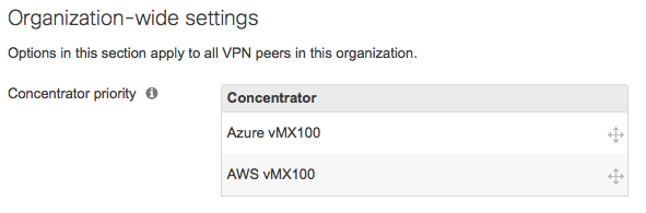
If, as per the above, more than one hub is advertising the same subnet or supernet address ranges, then the priority in which those routes are used by other hub MXs is configured in the Organization-wide settings section, as per the below:
Note: On MX-Z devices, traffic for the following services/tools will adhere to the route priority outlined in our MX Routing Behavior article
-
Advanced Malware Protection registration
-
Meraki Cloud Authentication
-
Meraki Cloud Communication on TCP ports 80, 443, and 7734
-
Ping and Dashboard Throughput Live Tools
-
List Updates for the following services
-
Content Filtering
-
IDS/IPS Rule Updates
-
Geo-IP Lists for Layer 7 Country-Based Firewall Rules
-
Furthermore, if an MX is configured for eBGP and receives a route that overlaps with our cloud connectivity network ranges, the MX’s cloud management traffic will follow that BGP route, so it is imperative that the MX, as well as it’s eBGP peer, have connectivity to everything listed on the Help > Firewall Info page in this scenario.
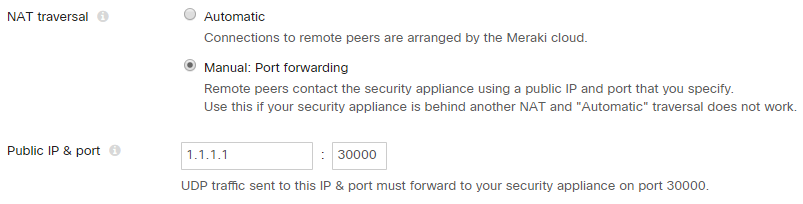
NAT Traversal
Finally, it is recommended to manually configure NAT traversal on a hub MX when it is in VPN concentrator mode behind an unfriendly NAT or aggressively timed CG-NAT device. The spokes that point to this hub will use the designated IP address and port, so ensure to use a public IP that is routable over the Internet. It is important that the upstream NAT device has a port forwarding rule to forward this traffic to the management IP address of this hub MX.
DC-DC Failover - Hub/DC redundancy (Disaster Recovery)
Summary
- Configure DC-DC Failover in order to protect against HW failure and DC outage / disaster.
Cisco Meraki's MX Datacenter Redundancy (DC-DC Failover) allows for network traffic sent across AutoVPN to failover between multiple geographically distributed datacenters.
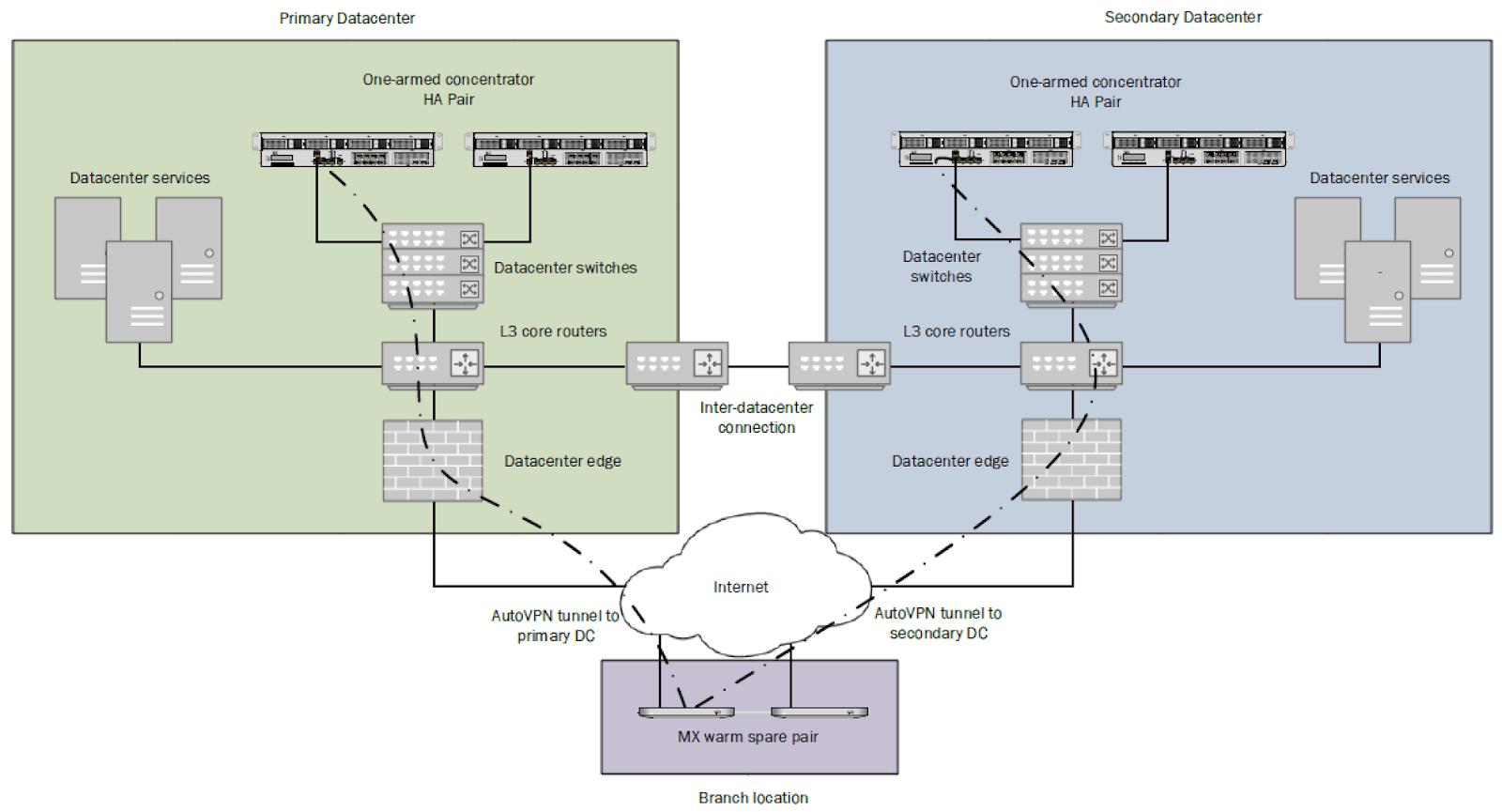
DC Failover Architecture
A DC-DC failover architecture is as follows:
- One-armed VPN concentrators or NAT mode concentrators in each DC
- A subnet(s) or static route(s) advertised by two or more concentrators
- Hub & Spoke topologies
- Split or full tunnel configuration
Operation
Deploying one or more MXs to act as VPN concentrators in additional data centers provides greater redundancy for critical network services.
In a DC-DC failover design, a remote site will form VPN tunnels to all configured VPN hubs for the network. For subnets that are advertised from multiple hubs, spokes sites will send traffic to the highest priority hub that is reachable.
Concentrator Priority
Concentrator priority setting determines the order in which VPN mesh peers will prefer to connect to subnets advertised by multiple VPN concentrators.
Additional DC-DC integration data can be found in this article.
In a distributed deployment of locations connected via a site-to-site VPN, a network administrator may need to have address translation performed on traffic traversing the site-to-site VPN. A 1:1 subnet translation can be used in cases where multiple locations have the same subnet present, but both need to participate in the site-to-site VPN. Alternatively, administrators may need to conserve IP space for large deployments. For this, 1:M NAT can be used to translate entire subnets into a single IP address that is exported across the site-to-site VPN.
For additional information relating to VPN Subnet translation, please refer to this article.
MX Firmware Version
- Use the latest GA (may be different per platform)
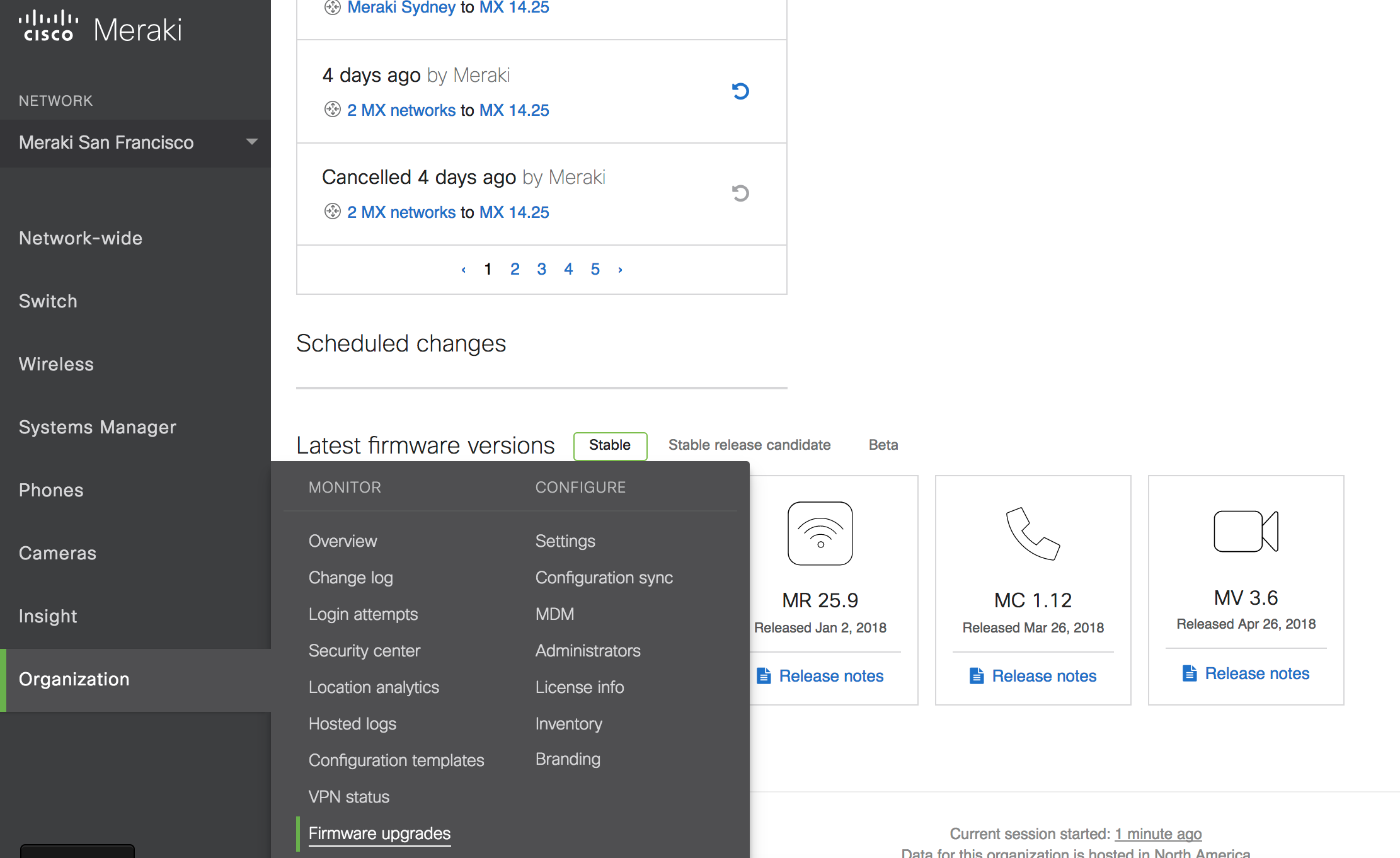
The Cisco Meraki Dashboard allows admins to easily schedule and reschedule firmware upgrades on their networks, opt-in to beta firmware releases, view firmware changelog notes, and to set maintenance windows.
Users will only be able to upgrade to the general release and beta versions. Information about these versions can be found under Organization > Monitor > Firmware Upgrades.
MX Hub Sizing
- Sizing may change based on the traffic blend and other potential factors. It is also changing with the introduction of firmware improvements (the following is for MX 13).
- These configurations have been tested successfully with retail/restaurant locations deploying 1000-1500 tunnels* per hub with MX250/MX400 (closer to 1000) and MX450/MX600 (closer to 1500).
- * Not locations, tunnels (think SD-WAN).
- Voice (and other small packet) traffic is notorious for high performance requirements and may result in a throughput and supported tunnel count that is lower than stated above.
Testing
This section captures key use cases identified to better test the MX in PoC environments.
The proposed topology for testing is detailed below. The Meraki SE and network admin will work together to refine this network architecture in the context of the POC success criteria agreed upon with the business.
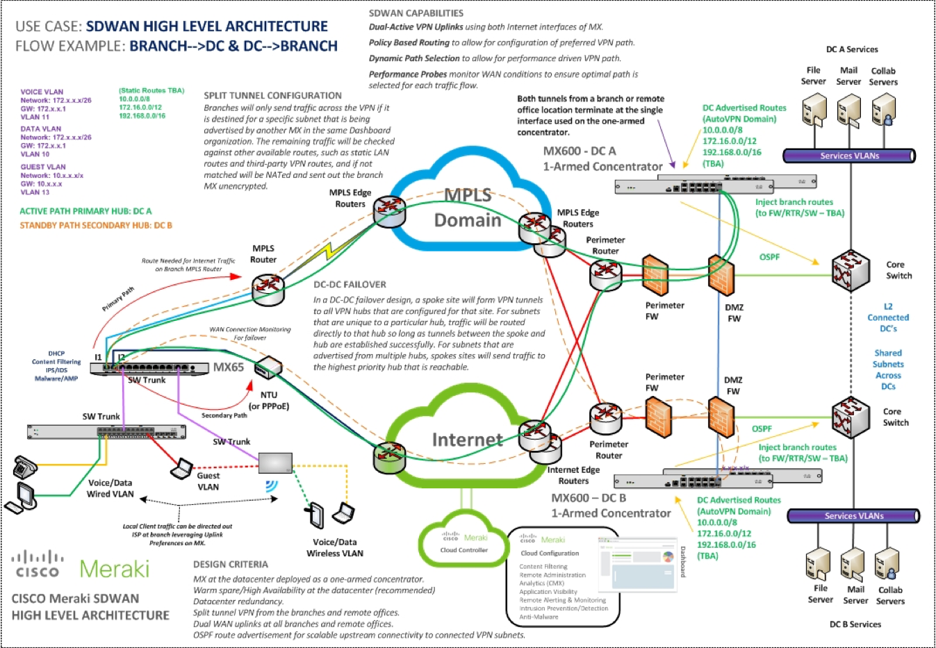
The following tests should be performed:
-
AutoVPN Connectivity
-
Verify that AutoVPN works correctly on the Cisco Meraki MX Security appliance in a 100% Cisco Meraki environment. Use case is for Internet access, data center access.
-
Ensure that solution works in full VPN and split-tunnelling configurations, delivering a ‘Branch-In-A-Box’ experience.
-
-
AutoVPN Failover
-
Verify that MPLS (or other) fails over to AutoVPN successfully when the MPLS private WAN (or other) path fails. Make sure the MX has access to the Meraki VPN registries.
-
Decommissioning Unused Sites
Meraki recommends that networks that have no further expected use be decommissioned from AutoVPN deployments by either disabling their VPN configurations, or by removing the devices in question from their networks. At larger scales, the Dashboard API can be used to ease this process.
The recommendation on this practice stems from the fact that previously learned points of contact from peers are not aged out of concentrators unless they’re rebooted. Over time - especially on concentrators that aren’t expected to have any periods of downtime - this can lead to unnecessary traffic being generated, as the concentrator reaches out to IP addresses and ports that are no longer in use, or even potentially in use by other networks.
-
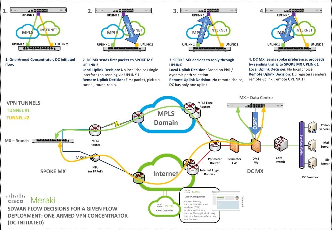
Meraki SD-WAN (MPLS/Internet)
-
Verify that the Meraki SD-WAN service functions as designed and provides support for MPLS and Internet carriage simultaneously.
-
The SD-WAN success relies on AutoVPN working correctly. Always check the communication to the VPN registry, specially when the MX has a DHCP address configured that can change. Each WAN has to reach the registry individually.
-
For more information, refer to our SD-WAN Deployment Guide
-
-
Transport Independence
-
Verify that transport independent links (e.g. MPLS, ADSL, etc) can be concurrently configured to support Auto-VPN overlay networks. Enable and configure multiple diverse uplink on the MX appliance. Configure flow preferences to pin traffic to a particular path, and/or load balancing.
-
-
3G/4G WAN Failover
-
Verify that a failover USB 3G/4G interface can be installed, enabled and configured on the MX appliance and that traffic can be redirected over this link during a WAN interface failure condition.
-
Check the supported USB modems in our 3G/4G Cellular Failover article
-
-
Highest rated
(rating)Recently updated
(date updated)Recently added
(date created)