
Private Cloud vMX Deployment Guide
Overview
The following guide will serve as a living document for deploying and troubleshooting the private cloud vMX solution. This document provides a walkthrough for setting up a virtual MX appliance on a Meraki reference UCS compute platform. After completing these steps outlined in this document, you will have a virtual MX appliance running on a UCS compute platform in your own private cloud.
Key Concepts
Before deploying a virtual MX, it is important to understand several key concepts.
Concentrator Mode
All MXs can be configured in either NAT or VPN concentrator mode. There are important considerations for both modes. For more detailed information on concentrator modes, click here.
One-Armed Concentrator
In this mode, the MX is configured with a single Ethernet connection to the upstream network. All traffic will be sent and received on this interface. This is the only supported configuration for vMX appliances serving as VPN termination points into your datacenter on UCS.
NAT Mode Concentrator
In this mode, the MX is configured with a single Ethernet connection to the upstream network and one Ethernet connection to the downstream network. VPN traffic is received and sent on the WAN interfaces connecting the MX to the upstream network and the decrypted, un-encapsulated traffic is sent and received on the LAN interface that connects the MX to the downstream network.
Note: A limited NAT mode capability can be enabled on the vMX in which traffic from the spokes will be NATed to the vMX's IP as it egresses the vMX in to your datacenter. Other capabilities of the NAT mode including DHCP, HA or multiple ports (LAN and WAN) are not supported. In each mode the vMX is still a one-armed appliance with one network interface
VPN Topology
There are several options available for the structure of the VPN deployment.
Split Tunnel
In this configuration, branches will only send traffic across the VPN if it is destined for a specific subnet that is being advertised by another MX in the same Dashboard organization. The remaining traffic will be checked against other available routes, such as static LAN routes and third-party VPN routes, and if not matched will be NATed and sent out the branch MX unencrypted.
Full Tunnel
In full tunnel mode all traffic that the branch or remote office does not have another route to is sent to a VPN hub.
vMX Architecture
The private cloud vMX solution operates on a Cisco UCS appliance that runs multiple Meraki vMX's on top. The following diagram illustrates the entire hardware and software stack of the solution.
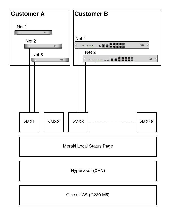
The virtualization stack is comprised of a Cisco UCS C220 M5 at the hardware level and on top of that it runs the XEN hypervisor. The UCS is secured by the same industry standard technology that the Meraki cloud leverages including secure boot via a hardware-based TPM module.
Connectivity
_(highlighted).png?revision=1&size=bestfit&width=968&height=107)
On the UCS chassis there are 8 network interfaces on the back as seen in the diagram above. Three of these interfaces are not used and should not be connected (circled in red). The 10G ethernet interface labeled "1" in the image below is used by the local status page (see section below) to connect to dashboard with a given authentication token to provision a vMX. The four (4) 10G SFP interfaces operate in an 802.3ad LACP bond. You can connect any number of these interfaces but they must be aggregated on the switch side if connecting multiple. This interface is used by the vMX instances to communicate with the Meraki cloud.
_(Highlighted).png?revision=1)
Addressing
The UCS chassis can be statically assigned using option "9 - Set System IP" (see screenshot below). This will open a GUI for setting a static IPv4 or IPv6 address.
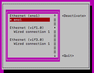
First you will need to activate your management connection (if it is not already). Navigate to "Activate a Connection"
Next, highlight the management interface eno1 (may also be shown as "Wired Connection 1") and select activate. If the only option says "deactivate" then the interface is already active. Quit and go back to the previous menu
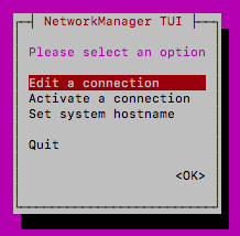
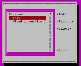
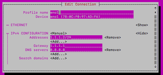
Select "Edit a connection" and highlight/edit eno1 (or "Wired connection 1" if that's what you activated above)
Change the IPv4 configuration method from automatic to manual and enter the IP (ensuring to add a subnet mask in CIDR formation)
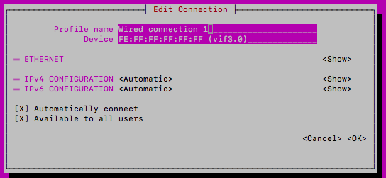
Once you start creating vMX instances, you may see another interface in the list often represented as "Wired connection 2" (if your management interface is represented as "Wired Connection 1" or it will show up as "Wired Connection 1" if the management interface is represented as "eno1". This interface pertains to the virtual interfaces that the vMX creates. In the screenshot below you'll see vif3.0 in brackets next to the device MAC. This will help you identify if you are editing the management interface or a VIF interface
Do not modify the VIF interface. Adding a static IP to this interface will have no barring on the vMXs that run off that interface. If you delete this interface, any vMXs that were created already will need to be deleted and recreated
Each vMX instance that runs on the UCS only supports DHCP assignment. The native VLAN that the SFP port(s) are uplinked to should be considered a provisioning VLAN that has DHCP running. Once a vMX is created and checks in to dashboard via it's DHCP-assigned address, a static IP and VLAN can then be set on dashboard to assign that vMX to its own customer VLAN.
When the UCS box boots it will pull two addresses via DHCP so the subnet attached to the ethernet interface above will need to be at least a /29 or larger to accommodate. The first address the appliance pulls is for the CIMC management interface and the second is for the Meraki local status page.
CIMC Interface
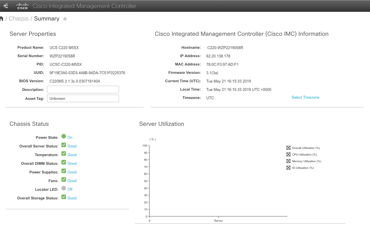
Every UCS comes with an embedded interface called the Cisco Integrated Management Console (CIMC). From this interface you can view overall health of the server including overall CPU utilization. When this CPU utilization starts to surpass the ~80% mark for sustained periods of time it will likely be time to begin procuring another box to scale out further on.
You can also launch a KVM/Java console from this interface to interact with the server as if you had a monitor plugged in locally and you can enable SNMP and other monitoring to alert you about various system health metrics.
The default log in credentials are Username: admin and Password: Cisco1234 or Password: password (you will be prompted to change the password after logging in if this was not set up already during the initial provisioning of the UCS)
Local Status Page
The solution contains a local status page for vMX lifecycle management which can be accessed via an SSH connection to the UCS
Credentials
The default credentials for accessing the local status page are:
Username: vmoperator
Password: meraki123 (should be changed once logged in)
SSH
To access the local status page open an SSH connection to the second IP address that the chassis pulled when it booted. In Windows the recommended application is Putty and from a Mac OSX/Linux terminal you can open a session using "ssh vmoperator@<IP>"
Capabilities
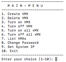
From the local status page a set of functions can be performed to manage your vMX deployment including:
-
Create a vMX
-
Delete a vMX
-
Start a vMX
-
Stop a vMX
-
Start all vMXs
-
Stop all vMXs
-
List vMXs
-
Change Password
-
Reboot System
Once a vMX has been provisioned on the chassis via the local status page it should check in to dashboard after ~3-5 minutes at which point it can be fully managed via dashboard just like any other Meraki device.
Provisioning
Once you have successfully accessed the local status page, creating a vMX is very simple.
Meraki Dashboard Configuration
Begin by creating a new Security Appliance network in your organization. This guide will walk you through creating a new network in the Meraki Dashboard.
Licensing
The Meraki Dashboard will require a VMX-S or VMX-M (not to be confused with the vMX100 license for vMX operating in AWS/Azure) license to be added before you are able to continue with the private cloud vMX solution. If you do not have access to a VMX-S or VMX-M license, please reach out to your Meraki Reseller or Sales Rep.
Once you have created the network and added the appropriate license you will be able to deploy a new small or medium vMX instance in your network by navigating to Security & SD-WAN > Monitor > Appliance Status and clicking on 'Add VMX-S' or 'Add VMX-M':
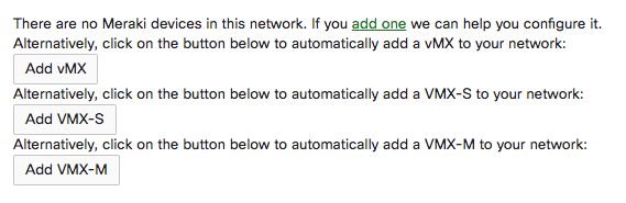
A note on the above, this page will be default show only the 'Add vMX' button if you have added a vMX100 license (for AWS/Azure vMX) and similarly will only show the 'Add vMX-S' or 'Add vMX-M' options once you have added a VMX-S or VMX-M license key. Please only deploy vMX100 instances (first option above) in AWS/Azure and the VMX-S/M instances on the private cloud vMX platform.
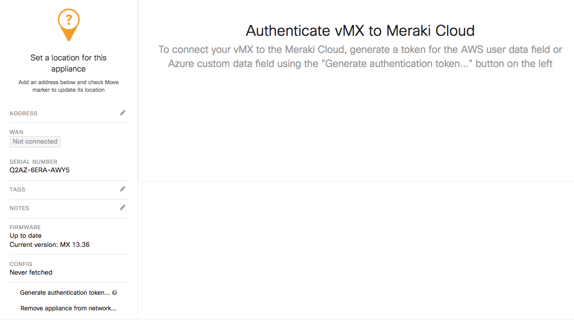
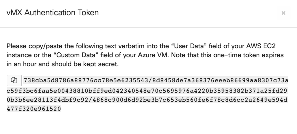
After you add the new vMX to your network, navigate to Security & SD-WAN > Monitor > Appliance Status and select “Generate authentication token” towards the bottom left of the page to generate and copy the token for use on the local status page
The authentication token must be entered into the local status page within 1 hour of generating it. If it has been more than 1 hour then a new token must be generated.
Local Status Page Provisioning
On the Local status page perform the following:
- Press "1" to create a vMX
- Select your instance size (small or medium). Refer to the sizing guide here for performance benchmarks of each
- Paste the authentication token copied from dashboard
- After a couple seconds you should see the serial and MAC of the vMX printed on screen and within ~60s the vMX creation should complete. The vMX should check in to dashboard over the next 3-5 minutes.
Next, follow the steps outlined in this guide to configure the vMX as a one-armed concentrator.
Use Cases
Multi-Tenancy
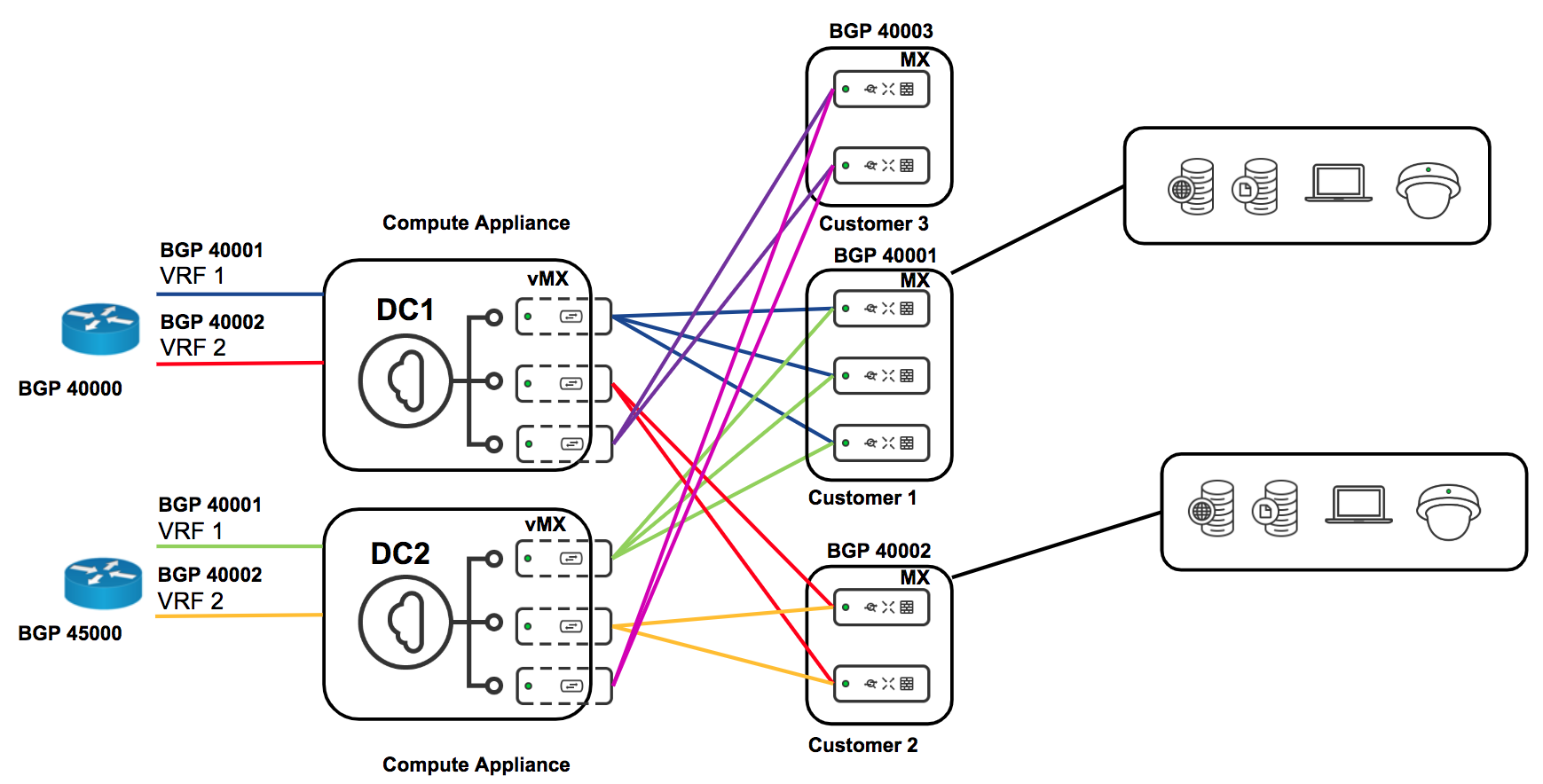
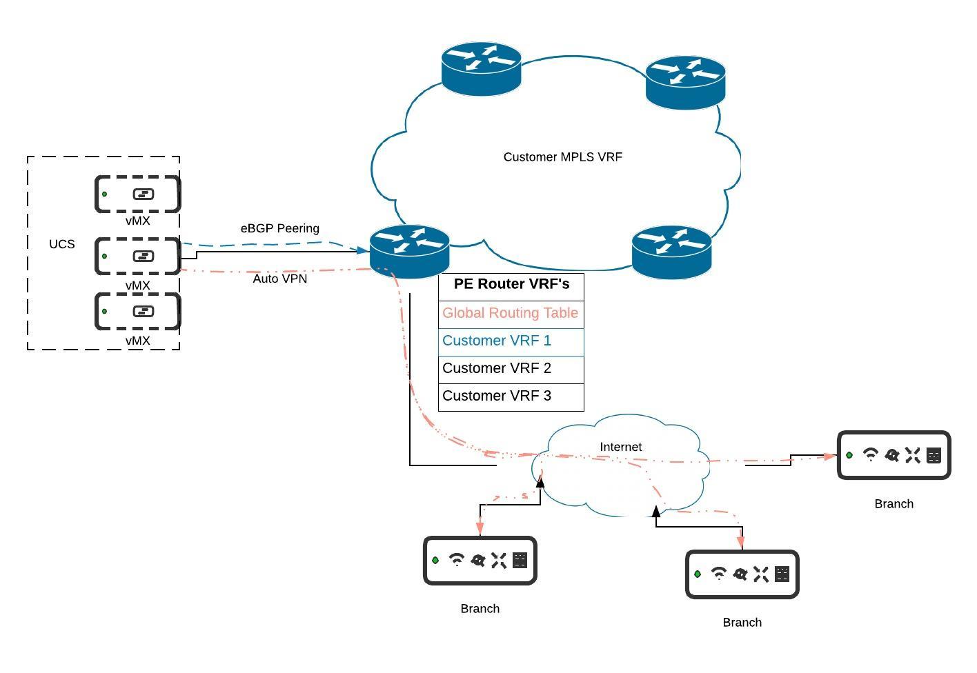
MPLS and BGP Integration with VRF's
For more details on this deployment setup please refer to the documentation here.
.jpeg?revision=1&size=bestfit&width=920&height=634)
Micro Segmentation with Source Based Routing
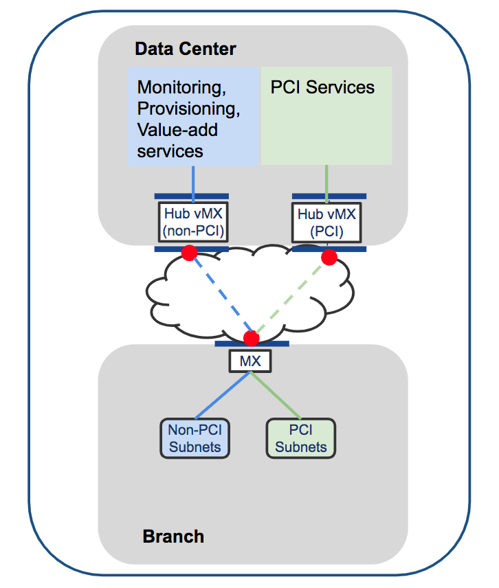
In MX15.4+ the ability to do source-based routing was introduced. This allows you to define a per-VLAN default route to either a local next hop on the LAN or to a VPN hub. We will focus on the VPN use-case (see diagram above).
At the branch you might have multiple VLANs which you want to keep truly segmented over the VPN and even at the DC. With a vMX-based solution you can spin up a vMX for each VLAN. At the branch you can direct VLAN 1 to hub 1, VLAN 2 to hub 2, etc. This will create a full-tunnel VPN for that VLAN to the specified hub. One such use-case for this kind of micro-segmentation could be for PCI compliance (although PCI compliance does not require this granular level of segmentation).
Troubleshooting
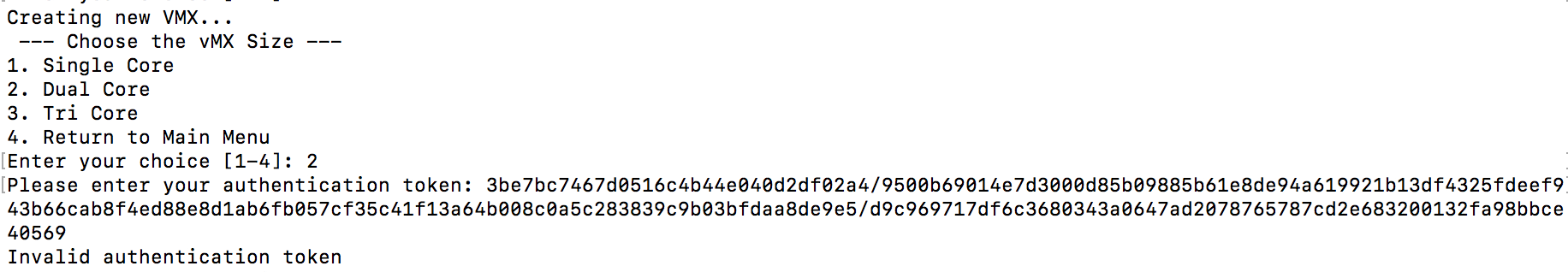
Invalid Authentication Token
If you get an invalid authentication token message when creating a vMX please generate and paste a new token from dashboard in to the local status page ensuring no additional characters or white spaces are appended before or after the token as you apply it.
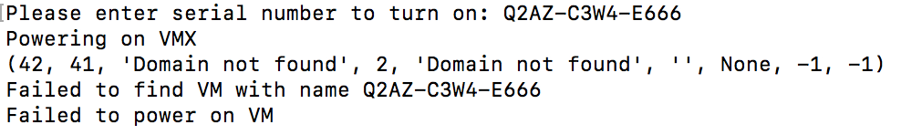
Failed to find VM with name
Entering an incorrect serial number when prompted while turning on, turning off or deleting a vMX will result in the error "Domain not found" along with a "failed to find VM with name Q2XX-XXXX-XXXX". Please ensure you enter the serial number as it is shown in the "List vMXs" (option 7) output. The easiest way to ensure correctness is to copy the serial number directly from the output of this tool and paste when prompted for the operations mentioned above.
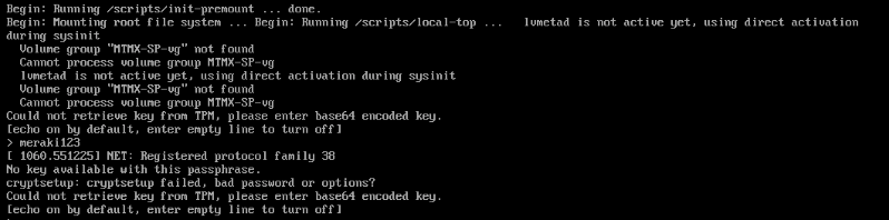
Could not Retrieve Key from TPM during Chassis Boot
Encountering the below message while the UCS is booting is indicative of system or hardware failure. Generally this should only happen if a critical component of the system is missing or has become disconnected from the motherboard. The most common example of this could be the 4 x 10G SFP riser card becoming dislodged (potentially while being moved/transported). Start by opening the chassis and ensuring all cards/components that are easily accessible such as the riser card are seated and re-seat as necessary.
If you continue to encounter this issue after following the above steps please reach out to your account rep/SE for further assistance
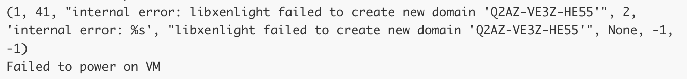
Libxenlight Failed to Create New Domain
If you get the error "libxenlight failed to create new domain" while creating a vMX it is likely that you have reached the capacity for the number of instances that can be created on a single box. This is especially true if you are oversubscribing instances to physical cores (ie. you have deployed more than 48 single core instances, 24 dual core or 16 tri-core instances on a given UCS).
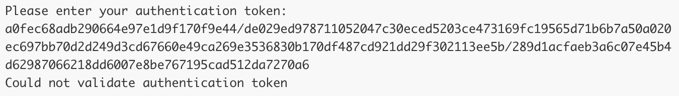
Could not Validate Authentication Token
If you get the error "could not validate authentication token" when you enter the authentication token on the local status page while attempting to create a vMX it typically means that the network connected to the Ethernet 1 interface on the chassis is not able to reach the internet or Meraki. Ensure this network and any upstream firewalls allow the port 7734 traffic as outlined on the Help > Firewall Info page on dashboard
vMX Not Checking in After Recreate
If a vMX was previously checking in to dashboard but was then deleted and recreated with a fresh auth token, you will need to recreate the instance both on the UCS as well as in dashboard due to security measures on our backend. To recreate the instance in dashboard perform the following:
- Navigate to Security & SD-WAN > Monitor > Appliance Status
- Click "Remove appliance from network" in the lower left of the page
- When the node is deleted, navigate back to Security & SD-WAN > Monitor > Appliance Status
- Click on "Add vMX" to create a new vMX node
- Generate a new auth token for this node and create the vMX on your UCS
No Add vMX Button
When navigating to Security & SD-WAN > Monitor > Appliance Status, if there is no "Add vMX" button please ensure the following two conditions are met:
- You have available vMX licenses in your license pool
- Your organization license status is not expiring in <30 days (yellow warning at the top of the Organization > Configure > License Info page)