
MR70 Installation Guide
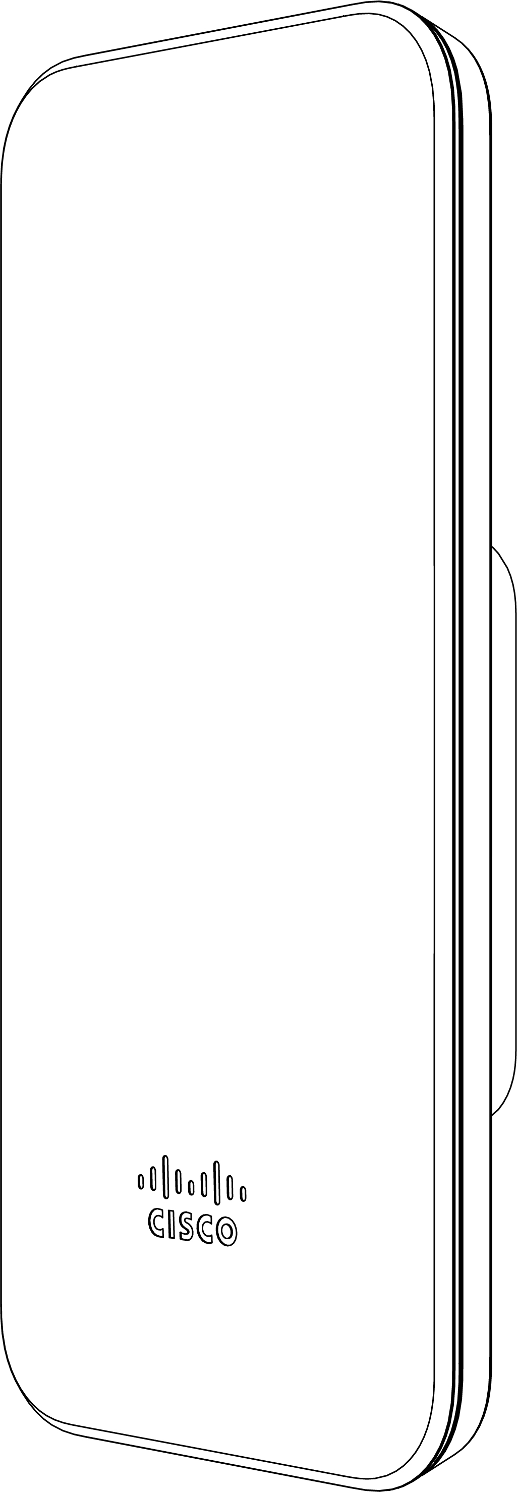
The Cisco Meraki MR70 is a dual-band enterprise class 802.11ac cloud-managed access point.
Package Contents
The MR70 package contains the following:
- MR70 Cloud-Managed Access Point
-
Mount cradle including built-in level tool
- Mount Kit
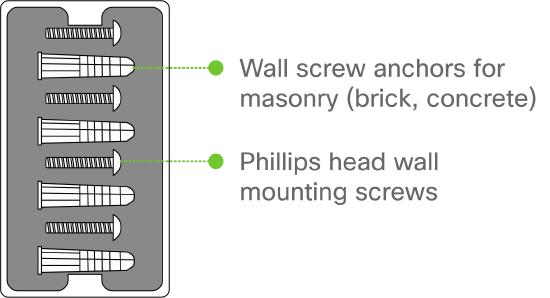
- Wall screws and wall screw anchors
Understanding the MR70
Your Meraki MR70 has the following features:
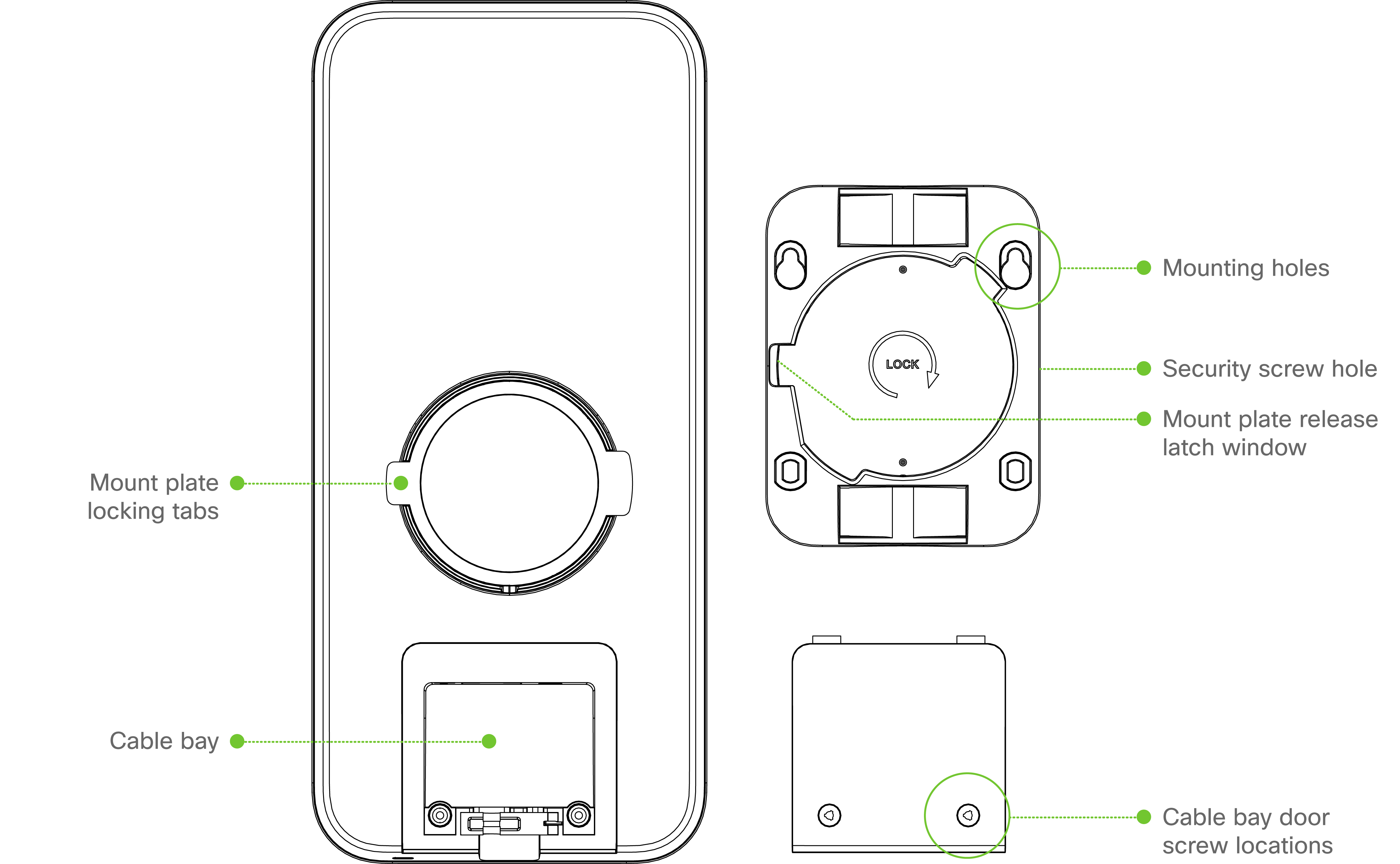
The mount cradle has the following features:
Security Features
The MR70 allows for physically securing the access point after installation:
- Security screw – The accessory kit includes screws that can be used to secure the access point to the mount cradle. Engaging the security screw prevents accidental dislodging and theft.
Ethernet Ports
The MR70 features a Gigabit Ethernet RJ45 port that accepts 802.3at and 802.3af power (labeled “Eth0, PoE”). This port should be used for uplink to your WAN connection.
Power Source Options
The MR70 access point can be powered using either the Meraki AC Adapter, PoE Injector (both sold separately), or a third-party PoE switch. The MR70 operates at full power with 802.3af PoE.
Factory Reset Button
If the button is pressed and held for at least five seconds and then released, the MR70 will reboot and be restored to its original factory settings by deleting all configuration information stored on the unit.
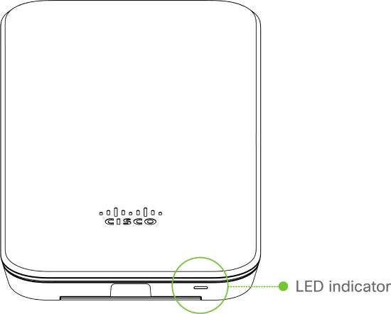
LED Indicators and Run Dark Mode
Your MR70 is equipped with a multi-color LED light on the front of the unit to convey information about system functionality and performance:
- Orange - AP is booting (permanent Orange suggests hardware issue)
- Rainbow - AP is initializing/scanning
- Blinking Blue - AP is upgrading
- Green - AP in Gateway mode with no clients
- Blue - AP in Gateway mode with clients
- Blinking Orange - AP can't find uplink
NOTE: Blinking Green LED indicates that the device is in site survey mode. Please see the Conducting Site Surveys with MR Access Points for more details.
The MR70 may be operated in “Run Dark” mode for additional security and to reduce the visibility of the access point. In this mode, the LED will not be illuminated. This mode may be enabled through Meraki dashboard.
Pre-Install Preparation
You should complete the following steps before going on-site to perform an installation.
Configure Your Network in Dashboard
The following is a brief overview only of the steps required to add an MR70 to your network. For detailed instructions about creating, configuring and managing Meraki wireless networks, refer to the online documentation (documentation.meraki.com).
- Login to http://dashboard.meraki.com. If this is your first time, create a new account.
- Find the network to which you plan to add your APs or create a new network.
- Add your APs to your network. You will need your Meraki order number (found on your invoice) or the serial number of each AP, which looks like Qxxx-xxxx-xxxx, and is found on the bottom of the unit. You will also need your Enterprise license key, which you should have received via email.
- Go to the map / floor plan view and place each AP on the map by clicking and dragging it to the location where you plan to mount it.
Check and Upgrade Firmware
To ensure your MR70 performs optimally immediately following installation, it is recommended that you facilitate a firmware upgrade prior to mounting your MR70.
- Attach your MR70 to power and a wired Internet connection. See the "Power the MR70" section for details.
- The MR70 will turn on and the LED will glow solid orange. If the unit does not require a firmware upgrade, the LED will turn either green (no clients associated) or blue (clients associated) within thirty seconds.
* If the unit requires an upgrade, the LED will begin blinking orange until the upgrade is complete, at which point the LED will turn solid green or blue. You should allow at least a few minutes for the firmware upgrade to complete, depending on the speed of your internet connection.
Check and Configure Firewall Settings
If a firewall is in place, it must allow outgoing connections on particular ports to particular IP addresses. The most current list of outbound ports and IP addresses for your particular organization can be found here.
Assigning IP Addresses to MR70s
All gateway MR70s (MR70s with Ethernet connections to the LAN) must be assigned routable IP addresses. These IP addresses can be dynamically assigned via DHCP or statically assigned.
Dynamic Assignment
When using DHCP, the DHCP server should be configured to assign a static IP address for each MAC address belonging to a Meraki AP. Other features of the wireless network, such as 802.1X authentication, may rely on the property that the APs have static IP addresses.
Static Assignment
Static IPs are assigned using the local web server on each AP. The following procedure describes how to set the static IP:
- Using a client machine (e.g., a laptop), connect to the AP wirelessly (by associating to any SSID broadcast by the AP) or over a wired connection.
- If using a wired connection, connect the client machine to the MR70 either through a PoE switch or a PoE Injector. If using a PoE switch, plug an Ethernet cable into the MR70’s Ethernet jack, and the other end into a PoE switch. Then connect the client machine over Ethernet cable to the PoE switch. If using a PoE Injector, connect the MR70 to the “PoE” port of the Injector, and the client machine to the “LAN” port.
- Using a web browser on the client machine, access the AP’s built-in web server by browsing to http://my.meraki.com. Alternatively, browse to http://10.128.128.128.
- Click on the “Uplink Configuration” tab. Log in. The default login is the serial number (e.g. Qxxx-xxxx-xxxx), with no password (e.g., Q2DD-551C-ZYW3).
- Configure the static IP address, net mask, gateway IP address and DNS servers that this AP will use on its wired connection.
- If necessary, reconnect the AP to the LAN.
Static IP via DHCP Reservations
Instead of associating to each Meraki AP individually to configure static IP addresses, an administrator can assign static IP addresses on the upstream DHCP server. Through “DHCP reservations,” IP addresses are “reserved” for the MAC addresses of the Meraki APs. Please consult the documentation for the DHCP server to configure DHCP reservations.
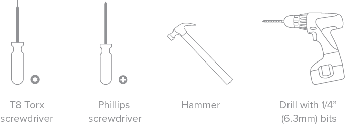
Collect Tools
You will need the following tools to perform an installation:
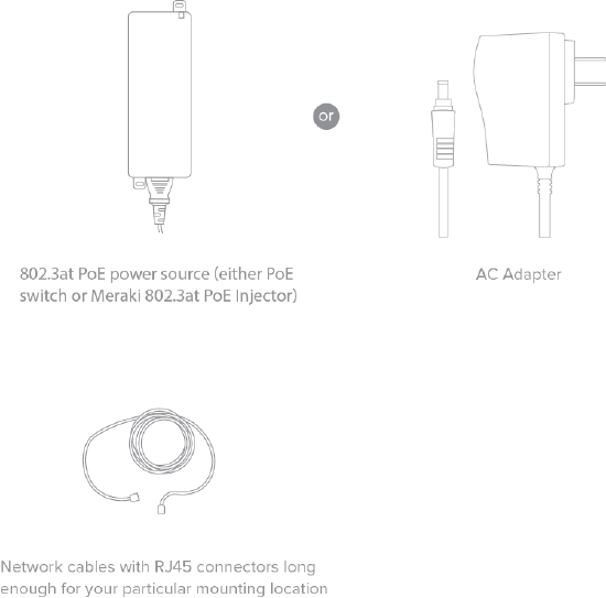
Collect Additional Hardware for Installation
You will need the following hardware to perform an installation:
Installation Instructions
Warning: Due to the heat dissipation in the back of APs during normal operation, please do not stack powered on APs on top of each other during pre-installation to avoid heat damage.
Choose Your Mounting Location
A good mounting location is important to getting the best performance out of your MR70 access point. Keep the following in mind:
- The device should have unobstructed line of sight to most coverage areas. For example, if installing in an office filled with workspaces divided by mid-height cubicle walls, installing on the ceiling or high on a wall would be ideal.
- Power over Ethernet supports a maximum cable length of 300 ft (100 m).
- If being used in a mesh deployment, the MR70 should have line of sight to at least two other Meraki devices. A Cisco Partner can help ensure that your AP placement is ideal.
Install the MR70
For most mounting scenarios, the MR70 mount cradle provides a quick, simple, and flexible means of mounting your device. The installation should be done in two steps. First, install the mount cradle to your selected location. Then, attach the MR70 to the mount cradle.
Attach the Mount Cradle
The MR70 mount cradle can be used to install your access point on a wall, solid ceiling, or pole.
Wall or Solid Ceiling Mount Using Mount Cradle
Using included wall anchors and screws, attach the mount cradle to your mounting wall or ceiling. It is recommended that the MR70 be mounted to a wall or solid ceiling using the mount cradle for physical security reasons.
Pole Mount Using Mount Cradle
Use mounting straps (not included) to secure the mount cradle to a pole. Thread the mounting straps through the mounting strap slots to secure the mount plate in a horizontal or vertical orientation. Vertical orientation is recommended for optimal RF coverage.
Connect Access Point to Ethernet and/or AC Adapter
Using a phillips head screwdriver, remove the screws that secure the Ethernet cover. Ensure that the Ethernet cable (and power cable, if applicable) is properly secured in the black cable gland. Secuire the Ethernet cover with the phillips head screwdriver.
Mount the MR70
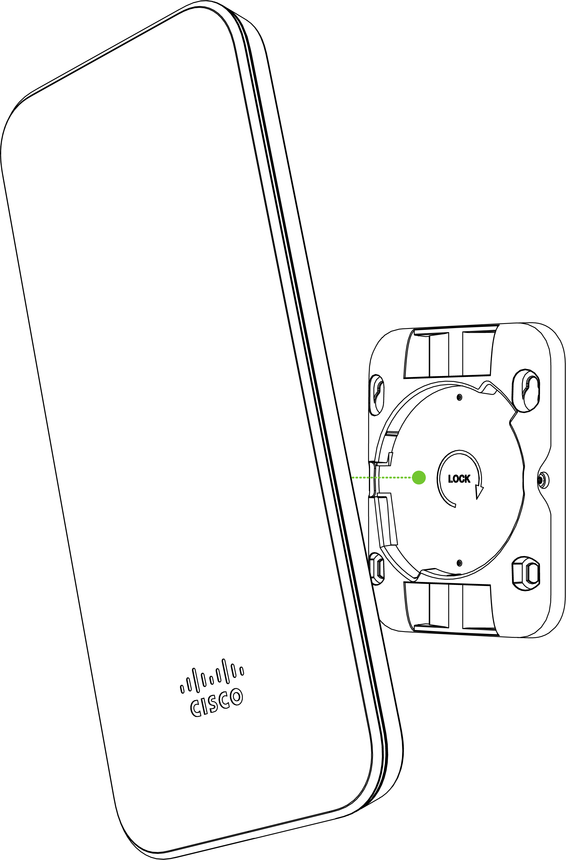
Attach the MR70 to the Mount Cradle
(This section applies to wall and/or solid ceiling where you have already installed the mount cradle.)
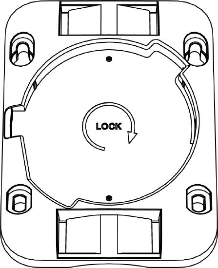
The MR70 attaches to the mount cradle with two tabs on the cradle that insert into the MR70, and is secured to the cradle using one screw.
To attach the MR70 to the mount cradle properly, line up the top edge of the AP with the top tab of the mount cradle. Since the cradle is already mounted to the wall, guide the MR70 towards the top tab and insert the top tab into the MR70’s slot.
Then, adjust the MR70 to guide the MR70’s bottom slot into the cradle’s bottom tab until it clicks into place. Once in place, the MR70 should be secured to the cradle by using one of the included screws in the cradle’s bottom tab.
To release the MR70 from the mount cradle, first remove the security screw that secures the MR70 to the cradle’s bottom tab. While holding the MR70 with one hand, press the cradle’s bottom tab upwards, releasing the MR70 from the bottom of the cradle. Then remove the MR70 from the cradle’s top tab.
Secure the MR70
Depending on your mounting environment, you may want to secure the MR70 to its mount location. If the MR70 has been installed using the mount cradle, it should be secured via security screw included with mount cradle.
Security Screw
Install the security screw in the lower mount cradle tab.
Verify Device Functionality and Test Network Coverage
- Check LEDs
- The Power LED should be solid green (or blue, if clients are connected). If it is flashing blue, the firmware is automatically upgrading and the LED should turn green when the upgrade is completed (normally within a few minutes). See the "LED Indicators" section for more details. .
- Note: Your MR70 must have an active route to the Internet to check and upgrade its firmware.
- Verify access point connectivity
- Use any 802.11 client device to connect to the MR70 and verify proper connectivity using the client’s web browser.
- Check network coverage
- Confirm that you have good signal strength throughout your coverage area. You can use the signal strength meter on a laptop, smart phone, or other wireless device.
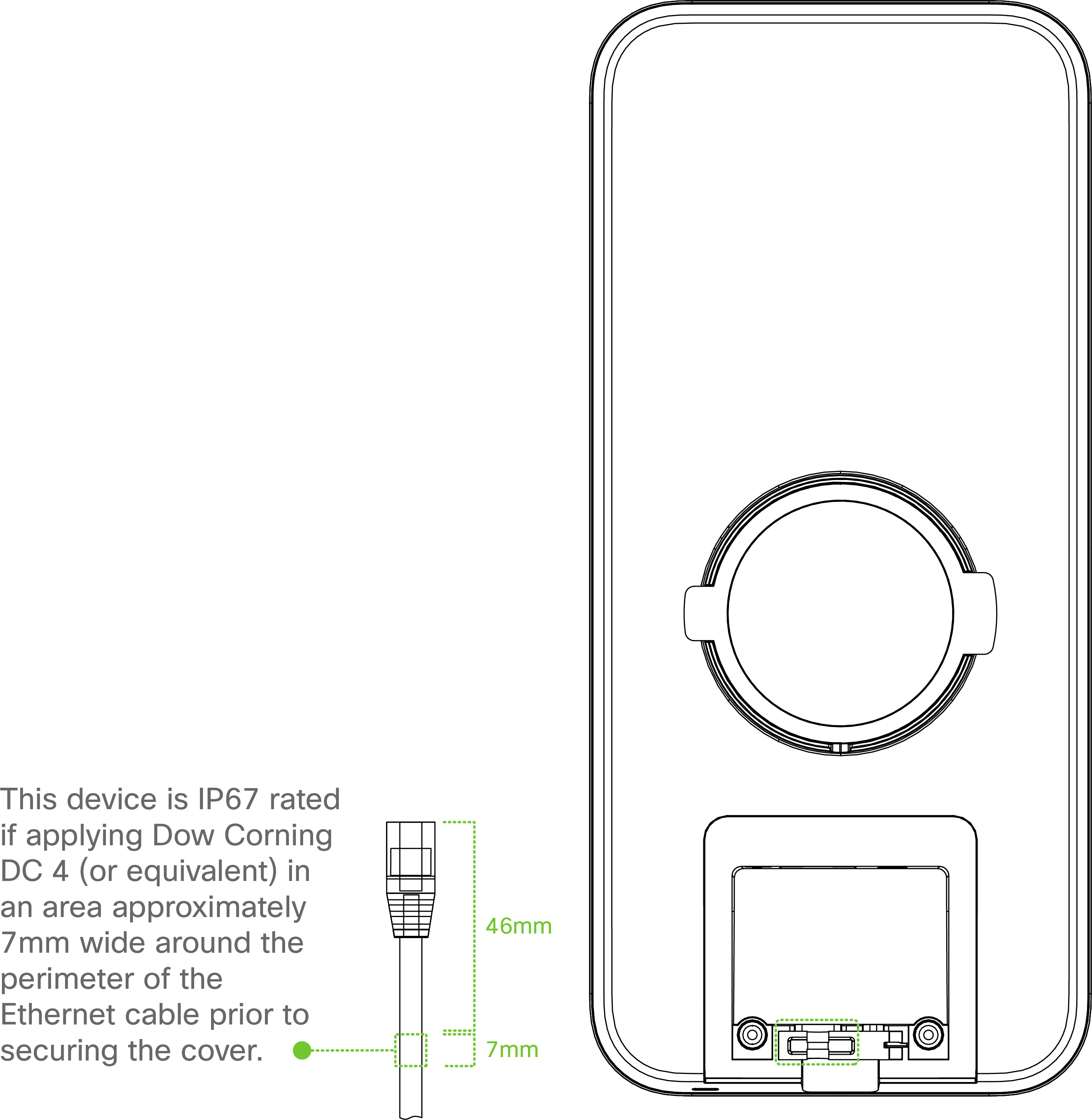
IP67 Rating
The MR70 is IP67 rated if Dow Corning DC 4 (or equivalent) is applied as shown below:
Warranty
Additional warranty information can be found on the MR70 Datasheet or on the Warranty Returns (RMA) page of the Cisco Meraki website.