
Private Cloud vMX with MPLS
This document walks through how to integrate the private cloud vMX solution in to a datacenter so a one-armed concentrator vMX can communicate with spokes on the internet as well as sites located on a traditional private MPLS network.
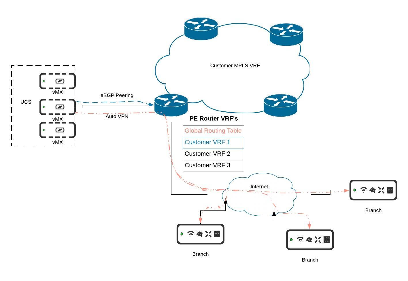.jpeg?revision=1&size=bestfit&width=804&height=554)
UCS Cabling & Config
When deploying the private cloud vMX solution please refer to the deployment guide here. In this example the UCS is uplinked to an ISR router via one of the 4 SFP slots on the UCS chassis. This connection is simply a trunk link.
ISR Router Setup
The port leading from the ISR to the UCS is set up as a trunk link. As stated in the deployment guide, it is not possible to statically assign a vMX an IP before it has checked in to dashboard. Once it has checked in an IP or VLAN can be assigned through dashboard. The UCS is connected on gig0/0/1, another ISR on gig0/0/2 and the internet on gig0/0/0. For the purpose of this example we will only focus on the gig0/0/0 and 0/0/1 ports only and not the rest of the MPLS backbone.
Interfaces
As discussed above, the gig0/0/0 interface connects to our internet circuit and gig0/0/1 is a trunk link to the UCS.
interface GigabitEthernet0/0/0
 ip address 10.100.0.2 255.255.0.0
!
interface GigabitEthernet0/0/1
 ip address 172.16.0.1 255.255.255.0
DHCP
A vMX cannot have a static address/VLAN assigned before it checks in to dashboard. The recommended design is to consider the untagged/native VLAN that the UCS is uplinked on as the provisioning VLAN. When a vMX is created it will pull an address via DHCP from this native VLAN and check in to dashboard. Once online a static IP and/or VLAN can be assigned via dashboard.
The config below will create this DHCP server for the untagged VLAN.
ip dhcp pool VMX
 network 172.16.0.0 255.255.255.0
 default-router 172.16.0.1
 dns-server 8.8.8.8
NAT
In order for our vMX traffic on gig0/0/1 to be routed out to the internet and have a successful return path we need to NAT it to the gig0/0/0 interface as it egresses the ISR.
The config below creates the VMX access list which defines the addresses on the inside we want to NAT on the outside. In this scenario we are allowing anything in the 172.16.0.0/16 subnet to be NAT translated on the egress. The 172.16.0.0/16 subnet will be further divided and assigned to our customer vMXs in each VRF.
ip access-list extended VMX
 permit ip 172.16.0.0 0.0.255.255 any
We add the below config to apply the access list to gig0/0/0 with a PAT overload.
ip nat inside source list VMX interface GigabitEthernet0/0/0 overload
VRF's
Below we will create a VRF for each customer. Each VRF requires a route distinguisher to be defined. An RD is 64 bits in length comprising three fields: type (two bytes), administrator, and value. There are currently three defined formats which can be used by a provider:

The choice of format is largely cosmetic. It makes no difference to BGP as the RD is effectively just a flat number prepended to a route. The choice of formats exists solely to allow for flexible administration of the number space.
In our config below we will create a type 2 RD for each customer.
ip vrf CUSTOMER1
 rd 1111:1
!
ip vrf CUSTOMER2
 rd 1111:2
We then need to create a subinterface on gig0/0/1 for each customer VRF and assign the VRF to the sub-interface. We also need to add these sub-interfaces as inside NAT interfaces so the vMX traffic on these interfaces can be translated when it egresses the ISR.
interface GigabitEthernet0/0/1.1
encapsulation dot1Q 101
ip vrf forwarding CUSTOMER1
ip address 172.16.101.1 255.255.255.252
ip nat inside
!
interface GigabitEthernet0/0/1.2
encapsulation dot1Q 102
ip vrf forwarding CUSTOMER2
ip address 172.16.102.1 255.255.255.252
ip nat inside
Finally we have to map the VMX access-list above to each VRF and PAT overload it on gig0/0/0 just as we did above for the untagged VLAN.
ip nat inside source list VMX interface GigabitEthernet0/0/0 vrf CUSTOMER1 overload
ip nat inside source list VMX interface GigabitEthernet0/0/0 vrf CUSTOMER2 overload
Internet Route Leak
Since each VRF is completely isolated from the Global Routing Table (GRT) and in most cases these VRF's are part of a traditional private MPLS backbone that has no internet reachability we will need to leak the default route from the GRT to each customer VRF. As long as we don't redistribute that static route in to the BGP process then it remains local to only this router and does not propogate or open the rest of the MPLS backbone to the internet.
We are using the prefix list GRT_TO_VRF to permit the default route in our route map. We then use that route map and add a route replicate in each customer VRF.
ip prefix-list GRT_TO_VRF seq 35 permit 0.0.0.0/0
!
route-map GRT_TO_VRF permit 10
match ip address prefix-list GRT_TO_VRF
route-replicate from vrf global unicast all route-map GRT_TO_VRF
BGP
The final piece of the ISR config is the BGP setup. We want to leverage BGP to share routes from our auto-VPN spokes on the internet to the sites on the MPLS VRF so they can all communicate with each other. Each customer's vMX will be placed on the respective customer VRF and will subsequently form an eBGP peering with it's VRF.
On the ISR we only need to create one BGP process and then define an address-family within for each customer VRF. Each vMX will subsequently be configured with the matching config to peer with its respective VRF.
router bgp 1
bgp router-id vrf auto-assign
bgp log-neighbor-changes
!
address-family ipv4 vrf CUSTOMER1
  network 172.16.101.0 mask 255.255.255.0
  neighbor 172.16.101.2 remote-as 1111
  neighbor 172.16.101.2 activate
exit-address-family
!
address-family ipv4 vrf CUSTOMER2
  network 172.16.102.0 mask 255.255.255.0
  neighbor 172.16.102.2 remote-as 2222
  neighbor 172.16.102.2 activate
exit-address-family
vMX Setup
To configure BGP on the vMX concentrator please follow the guide here. In this example we enabled BGP on our CUSTOMER1 vMX, defined our ASN, neighbor IP and remote AS for CUSTOMER1 to match the configuration above.

In the event logs we see the peering establish between the vMX and its respective VRF

Complete ISR Config
ip vrf CUSTOMER1
 rd 1111:1
 route-replicate from vrf global unicast all route-map GRT_TO_VRF
!
ip vrf CUSTOMER2
 rd 1111:2
 route-replicate from vrf global unicast all route-map GRT_TO_VRF
!
ip dhcp pool VMX
 network 172.16.0.0 255.255.255.0
 default-router 172.16.0.1
 dns-server 8.8.8.8
!
interface GigabitEthernet0/0/0
 ip address 10.100.0.2 255.255.0.0
 ip nat outside
 negotiation auto
!
interface GigabitEthernet0/0/1
 ip address 172.16.0.1 255.255.255.0
 ip nat inside
 negotiation auto
!
interface GigabitEthernet0/0/1.1
 encapsulation dot1Q 101
 ip vrf forwarding CUSTOMER1
 ip address 172.16.101.1 255.255.255.252
 ip nat inside
!
interface GigabitEthernet0/0/1.2
 encapsulation dot1Q 102
 ip vrf forwarding CUSTOMER2
 ip address 172.16.102.1 255.255.255.252
 ip nat inside
!
router bgp 1
 bgp router-id vrf auto-assign
 bgp log-neighbor-changes
 !
 address-family ipv4 vrf CUSTOMER1
  network 172.16.101.0 mask 255.255.255.0
  neighbor 172.16.101.2 remote-as 1111
  neighbor 172.16.101.2 activate
 exit-address-family
 !
 address-family ipv4 vrf CUSTOMER2
  network 172.16.102.0 mask 255.255.255.0
  neighbor 172.16.102.2 remote-as 2222
  neighbor 172.16.102.2 activate
 exit-address-family
!
ip default-gateway 10.100.0.1
ip nat inside source list VMX interface GigabitEthernet0/0/0 overload
ip nat inside source list VMX interface GigabitEthernet0/0/0 vrf CUSTOMER1 overload
ip nat inside source list VMX interface GigabitEthernet0/0/0 vrf CUSTOMER2 overload
ip route 0.0.0.0 0.0.0.0 10.100.0.1
!
ip access-list extended VMX
 permit ip 172.16.0.0 0.0.255.255 any
!
ip prefix-list GRT_TO_VRF seq 35 permit 0.0.0.0/0
!
route-map GRT_TO_VRF permit 10
 match ip address prefix-list GRT_TO_VRF