
CW9172H Installation Guide
The Cisco Wireless CW9172H is a Tri-band, Tri-radio, enterprise-class, Wi-Fi 7, cloud-managed access point supporting 2.4 GHz, 5 GHz, and the newly opened unlicensed 6 GHz frequency bands. Designed for moderate-density environments of hospitality, education, regional branches, retail and health care with wired and wireless connectivity, the CW9172H meets the needs of the most demanding environments. The access point also includes a fourth radio dedicated to optimizing the RF environment and securing the airwaves. The CW9172H also has an additional Bluetooth Low Energy (BLE) capable radio used for location and other IoT applications.
About this Guide
This guide provides instructions on how to install and configure your CW9172H access points. It also provides mounting instructions and limited troubleshooting procedures. For more wireless installation guides, refer to the wireless installation guides section on our documentation website.
Product Overview
Physical Specifications
|
CW9172H |
|
Interfaces
|
|
Power
|
|
Note: PoE Injector sold separately Note: Actual power consumption may vary depending on the AP usage. Note: It is required that you ensure that CDP and/or LLDP is enabled to allow proper power negotiation |
|
Environment
|
|
Physical Security
|
Product View and Physical Features
Your CW9172H has the following features:
CW9172H Face View

-
Security Screw Hole (for Cisco AIR-AP-BRACKET-W4 only)
-
Status LED
-
Console Port
CW9172H Back View

4. Security Screw Hole (for Cisco AIR-AP-BRACKET-W4 only)
5. Uplink Ethernet Port
6. Reset button
7. Pass through Port
8. Security Screw Hole (for CW-MNT-H1 only)
9. Bracket Lock Slot (for CW-MNT-H1 only)
CW9172H Port View

10. Bracket release (for CW-MNT-H1 only)
11. Pass through Port (with Cover)
12. LAN Port 1 (PoE Out)
13. LAN Port 2
14. LAN Port 3
15. Security Screw Hole (for CW-MNT-H1 only)
Mounting Brackets
The CW9172H has a new mounting bracket CW-MNT-H1, which will be the default wall mounting option. It’s also compatible with the legacy Meraki mount MA-MNT-MR-H1A, and Cisco Catalyst mount AIR-AP-BRACKET-4.
The CW9172H has an option to allow the access point to be placed horizontally on a desk using the CW-ACC-DESK1-00 accessory.
Physical Security Features
The CW9172H features multiple options for physically securing the access point after installation:
1. Security screw – The accessory kit includes screws that can be used to secure the access point to the mount cradle. Engaging the security screw prevents accidental dislodging and theft.
2. Kensington lock – For desktop placements, the desktop mount accessory, CW-ACC-DESK1-00, has a Kensington lock attachment that allows it to be secured to any nearby permanent structure using a standard Kensington lock.
3. LAN Port Security Cover - For wall mount installations, the LAN ports can be covered and secured with the Port Lock accessory, CW-MNT-H3-00 and prevents the removal of ethernet cables from the LAN ports.
Ethernet Ports
Uplink
The CW9172H features one RJ45 Uplink Ethernet port capable of operating at 100/1000/2.5G BASE-T Ethernet (RJ45).
 <..> 2.5G ϟ
The labeled “<..> 2.5 ϟ” accepts 802.3af , 802.3at and 802.3bt power. This port is typically used as the primary uplink to your LAN/WAN.
- The CW917HI needs 802.3bt, class 5 (up to 45W) for full operation of AP. They can operate with 802.3at power, but with a degraded operation.
- When operated with 802.3af, the AP powers up and connect to the Meraki Dashboard, but the 2.4GHz radio will be operating at 1x1 and all other radios will be operationally down.
- Cat 6/6A cabling is recommended for CW9172, as they support speeds up to 10Gig. Cat 5e supports speeds up to 5Gig.
LAN Access Ports
The CW9172H features 3x LAN ports labeled 1 through 3. Port 1 may provide 802.3af out to an end device if the CW9172H is powered via a 802.3bt, class 5 (up to 45W) power source. Configuration details can be found in the AP port profiles article.
Power Source Options
CW9172H can be powered by 802.3bt capable PoE ports. The AP is capable of operating at its full capacity when powered by a single 802.3bt Class 5 or higher with 45W for the AP to operate at full capacity. If only 802.3at 30W Class 4 (PoE+) power is provided to the AP, it is still fully functional in terms of Wi-Fi spatial streams and scanning and IoT radios, but cannot provide the full 15.4W on the PoE-out port. The table below indicates the different modes of PoE power input and the expected operation of the AP.
|
PoE |
Ethernet Speed |
2.4 GHz |
5GHz |
6GHz |
Scan |
IOT |
PoE Out |
|---|---|---|---|---|---|---|---|
|
AF |
1 Gig |
2x2 |
OFF |
OFF |
ON |
OFF |
OFF |
|
AT |
2.5 Gig |
2x2 |
2x2 |
2x2 |
ON |
ON |
ON (7W)* |
|
BT |
2.5 Gig |
2x2 |
2x2 |
2x2 |
ON |
ON |
ON (15.4W) |
* CW9172H may provide up to Class 2 7W on the PoE-out port, if the input is Class 4 30W, starting with MR 32.1.6 firmware. Prior to that firmware level, the PoE-out port would remain OFF if the AP only gets 30W from the PoE port or injector.
CW9172H APs can be powered by the PoE power in different modes as mentioned above when using a PoE-capable switch. CW9172H can also be powered by a single 802.3bt capable PoE injector CW-INJ-8 Cisco multiGigabit 802.3bt Power Over Ethernet Injector or MA-INJ-6 - Meraki multiGigabit 802.3bt Power over Ethernet Injector.
Factory Reset Button
If the button is pressed and held for at least sixty seconds and then released, the AP will reboot and be restored to its original factory settings by deleting all configuration information stored on the unit.
Below is the sequence of reset:
Approx 5 seconds - Blink Green for Meraki Mode
More than 10 seconds - Clear config
More than 20 seconds - Full reset, maintain management mode
More than 30 seconds - Clear FIPS config (Only for Catalyst Mode)
More than 60 seconds - Factory reset
More than 90 seconds - Abort reset
LED Indicators and Run Dark Mode
Your access point is equipped with a multi-color LED light on the front of the unit to convey information about system functionality and performance:
-
Orange - AP is booting (permanent Orange suggests hardware issue)
-
Rainbow - AP is initializing/scanning
-
Blinking Blue - AP is upgrading
-
Green - AP in Gateway mode with no clients
-
Blue - AP in Gateway mode with clients
-
Blinking Orange - AP can't find uplink
Blinking Green LED indicates that the device is in site survey mode. Please see the Conducting Site Surveys with MR Access Points for more details.
The CW9172H access point may be operated in the “Run Dark” mode for additional security and to reduce the visibility of the access point. In this mode, the LED will not be illuminated. This mode may be enabled through the Meraki Dashboard.
Package Contents
The access point packages contain the following:

-
CW9172H Cloud Managed Access Point
-
Wall Plate Mounting Brackett (CW-MNT-H1)
-
Pass through cable jumper
-
Allen-key / Security Release Tool
-
Long security screw
-
2x screws (Flat HD T8 M2.5xL12)
Safety and Warnings
These operations must adhere to full compliance with all applicable local laws. Please take the following into consideration for safe operation:
-
Power off the unit before you begin. Read the installation instructions before connecting the system to the power source.
-
Before you work on any equipment, be aware of the hazards involved with electrical circuitry, and be familiar with standard practices for preventing accidents.
-
Read the wall-mounting instructions carefully before beginning installation. Failure to use the correct hardware or to follow the correct procedures could result in a hazardous situation to people and damage to the system.
-
This product relies on the building’s installation for short-circuit (overcurrent) protection. Ensure that the protective device is rated not greater than 15 A, 125 Vac, or 10A, 240 Vac.
-
Please only power the device with the provided power cables or standard PoE to ensure regulatory compliance.
Pre-install Preparation
The following steps should be completed before going on-site to perform an installation.
Configure your Dashboard Network
The following is a simple overview of the steps to add an access point to your network. For detailed guidance on setting up and managing Meraki wireless networks, visit the online documentation at documentation.meraki.com.
- Navigate to http://dashboard.meraki.com and log in. Create a new account if logging in for the first time.
- Locate the network where you want to add the access points or create a new network.
- Add the access points to your network using the Meraki order number from your invoice or the serial number on the bottom of each device (e.g., Qxxx-xxxx-xxxx). Use the license key sent to your email.
- Open the map / floor plan view and place each access point on the map. Click and drag each access point to its planned mounting location.
If the organization’s networks have Meraki Sensors, create a separate network for the CW9172H for staging. After the CW9172H connects to the cloud and updates its firmware, move the access point to the intended (CW9172H has to operate) network.
Check and Set Firmware
Upgrade the firmware before mounting the access point to ensure optimal performance after installation.
-
Attach your AP to power and a wired Internet connection. See the Getting Power to the AP section for details.
-
The AP will turn on and the LED will glow solid orange. If the unit does not require a firmware upgrade, the LED will turn either green (no clients associated) or blue (clients associated) within thirty seconds.
If the unit requires an upgrade, the LED will begin blinking blue until the upgrade is complete, at which point the LED will turn solid green or blue. You should allow at least a few minutes for the firmware upgrade to complete, depending on the speed of your internet connection.
Check and Configure Upstream Firewall Settings
If a firewall is in place, it must allow outgoing connections on particular ports to particular IP addresses. The most current list of outbound ports and IP addresses for your particular organization can be found on the firewall configuration page in your dashboard.
Assigning an IP Address
All gateway APs (An AP with Ethernet connections to the LAN) must be assigned a routable IP address. These IP addresses can be dynamically assigned via DHCP or statically assigned.
Static Assignment
-
Static IPs are assigned using the local web server on each AP. The following procedure describes how to set the static IP:
-
Using a client machine (e.g., a laptop), connect to the AP wirelessly (by associating to any SSID broadcast by the AP) or over a wired connection.
-
If using a wired connection, connect the client machine to the AP either through a PoE switch or a PoE Injector. If using a PoE switch, plug an Ethernet cable into the AP’s Ethernet jack, and the other end into a PoE switch. Then connect the client machine over Ethernet cable to the PoE switch. If using a PoE Injector, connect the AP to the “PoE” port of the Injector, and the client machine to the “LAN” port.
-
Using a web browser on the client machine, access the AP’s built-in web server by browsing to http://my.meraki.com. Alternatively, browse to http://10.128.128.128.
-
Click on the “Uplink Configuration” tab. Log in. The default login is the serial number (e.g. Qxxx-xxxx-xxxx), with no password (e.g., Q5BA-5678-ZYWX).
-
Configure the static IP address, netmask, gateway IP address and DNS servers that this AP will use on its wired connection.
-
If necessary, reconnect the AP to the LAN.
Static IP via DHCP Reservations
-
Instead of associating to each Meraki AP individually to configure static IP addresses, an administrator can assign static IP addresses on the upstream DHCP server. Through “DHCP reservations,” IP addresses are “reserved” for the MAC addresses of the Meraki APs. Please consult the documentation for the DHCP server to configure DHCP reservations.
Collect Tools
You will need the following tools to perform an installation:

Phillips screwdriver, Hammer (optional), Drill with 0.1360-in. [3.4772 mm] (optional) - depending on install type.
The universal mounting when attached directly to a wall or a ceiling requires four #8 screws (not included).
Collect Additional Hardware for Installation
You will need the following hardware to perform an installation:

PoE Power Source (either PoE switch or Meraki PoE Injector) and network cables with RJ45 connectors long enough for your particular mounting location.
CW9172H can be powered by a PoE Switch or a PoE Injector.
Installation Instructions
Avoid stacking powered-on access points during pre-installation or staging to prevent heat damage from normal heat dissipation.
Choose Your Mounting Location
Choose a suitable mounting location to ensure optimal access point performance. Consider the following:
- The device should have an unobstructed line of sight to most coverage areas. For example, if installing in an office filled with workspaces divided by mid-height cubicle walls, installing on the ceiling or high on a wall would be ideal.
- Power over Ethernet supports a maximum cable length of 300 ft (100 m).
- If being used in a mesh deployment, the AP should have a line of sight to at least two other Meraki devices. A Cisco Partner can help ensure that your AP placement is ideal.
Install the CW9172H AP
The CW9172H wall mount cradle offers a quick and flexible mounting option. First, install the cradle at the chosen location. Then, attach the CW9172H to the wall mount cradle.
The install procedure in this section is applicable to the default wall mount that ships with the AP (CW-MNT-H1) or Meraki wall mount (MA-MNT-MR-H1A).
Attach the Wall Mount Cradle
The CW9172H can be mounted to a single gang junction box and European outlet boxes (mounting screws are not included).
Using appropriate mounting hardware for your specific type of junction box, attach the mount cradle to the junction box.
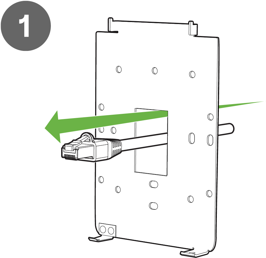_image.png?revision=1&size=bestfit&width=434&height=420)
_image.png?revision=1&size=bestfit&width=365&height=460)
Attach the CW9172H to the Wall Mount Cradle
To attach the CW9172H to the mount cradle properly, line up the top edge of the AP with the top tab of the mount cradle. Since the cradle is already mounted to the wall, guide the CW9172H towards the top tab and insert the top tabs into the CW9172H slot. Plug in the Uplink Ethernet cable. If there is a Pass thru device, plug in the cable to the Pass Thru Port.

Adjust the CW9172H to align its bottom slot with the cradle's bottom tab and push until it clicks into place. Secure the CW9172H to the cradle using one of the included screws in the cradle’s bottom tab.

Secure the CW9172H
Depending on your mounting environment, secure the CW9172H to the mount location. Your CW9172H can be secured via security screw (Torx security screws are included).

Ejecting CW9172H from mount plate
Remove the security screw from the cradle’s bottom tab to release the CW9172H from the mount cradle.
_image.png?revision=1&size=bestfit&width=562&height=596)

Hold the CW9172H with one hand and use the eject tool to trigger the release mechanism. Remove the CW9172H from the cradle’s top tab.

Install CW9172H with Cisco Catalyst Bracket (AIR-AP-BRACKET-W4)
The CW9172H is backward compatible with the Cisco Catalyst Wall Mount Bracket (AIR-AP-BRACKET-W4). You can replace the existing access point mounted on the AIR-AP-BRACKET-W4 with the CW9172H without installing a new wall mount.
Attach the Wall Mount Cradle
The CW9172H can be mounted to a single gang junction box and European outlet boxes (mounting screws are not included).
Using appropriate mounting hardware for your specific type of junction box, attach the mount cradle to the junction box.


For installations with a pass-through device, attach the pass-through cable to the pass-through port on the back side. If the uplink Ethernet cable connects to the bottom uplink port instead of the back, use the jumper cable to connect the uplink port and pass-through port on the back side.

Adjust the CW9172H to guide the CW9172H’s bottom slot into the cradle’s bottom tab until it clicks into place.
Secure the CW9172H
Depending on your mounting environment, secure the CW9172H to its mount location. Your CW9172H can be secured via security screw on the top. (Torx security screws are included).
Secure the CW9172H to its mount location using a security screw on the top. Torx security screws are included.

Attach the sticker cover once the screw is tightened and in place.

Ejecting CW9172H from mount plate
Remove the sticker and unscrew the security screw with the Allen-key Tool.

Remove the Access Point from the wall mount and remove the cables.


Install CW9172H with Wall Spacer Accessory
The CW-ACC-SPACER1-00 is a wall mount accessory designed to be used with CW9172H Access Point. The accessory is meant to be used in installations where additional cabling outlets are needed without having to use additional wall plates, thus making deployments aesthetically pleasing.
Package Contents

-
CW-ACC-SPACER1-00
-
2x Male to Female Ethernet Adapter
-
1x Security Release / Allen-Key Tool
-
1x Security Screw (Flat Head T8 M2.5x L12)
Installation Instruction
Use screws to Wall Mount the Spacer CW-ACC-SPACER1-00 and attach to the wall.

Remove the mouse hole tabs to route the Ethernet cable and the Pass thru cable on the sides or from the bottom.

Attach the Male to Female Ethernet Adapter that comes with the accessory kit to the Wall Mount. Route the Uplink Ethernet cable through the hole and plug into the Ethernet adapter.

Attach the Male end of the Ethernet adapter to the uplink port of the CW9172H Access Point. If there is a pass-through device, use the second Male to Female adapter to attach the male end of the ethernet adapter to the Pass thru port. Alternatively, if the bottom pass-through port is used to attach the uplink ethernet cable, use the jumper cable to connect the Uplink port and the Pass-through port in the back.
_image.png?revision=1&size=bestfit&width=627&height=540)
_image.png?revision=1&size=bestfit&width=711&height=251)
Adjust the CW9172H’s bottom slot with the cradle’s bottom tab and push until it clicks into place. Secure the CW9172H to the cradle using one of the included screws in the cradle’s bottom tab.
Connect the uplink Ethernet cable to the bottom pass-through port if the back ports are connected with the jumper cable.


Ejecting CW9172H from the Wall Spacer Mount
Remove the security screw from the cradle’s bottom tab to release the CW9172H from the mount cradle.
_image.png?revision=1&size=bestfit&width=441&height=456)
_image.png?revision=1&size=bestfit&width=433&height=434)
Hold the CW9172H with one hand and use the eject tool to trigger the release mechanism. Detach the CW9172H from the cradle’s top tab.

After ejecting the CW9172H, unplug the Ethernet cable from the adapter. Remove the Ethernet adapter and unscrew the accessory from the wall.
_image.png?revision=1&size=bestfit&width=625&height=264)
_image.png?revision=1&size=bestfit&width=472&height=426)
Install CW9172H with Port Lock Accessory
The CW-MNT-H3-00 is a wall mount accessory designed to be used with CW9172H Access Point. The accessory is meant to be used in installations where physical cable security is needed to prevent individuals from attempting to connect or disconnect wired devices to/from the CW9172H LAN Access Ports. This allows for organizations to securely implement wired guest services with ease of mind knowing that the physical cabling infrastructure will not be tampered with.
Package Contents

-
1x Port Lock Base
-
1x Port Lock Cover
-
1x Security Allen-Key Tool
-
1x Security Long Screw (1x 25mm Torx)
-
2x Security Short Screw (2x 12mm Torx)
Installation Instructions
Lay the CW9172H Mount Cradle over the CW-MNT-H3 aligning the holes. Use screws to attach the CW-MNT-H3 to the wall or junction box.

Lay the CW9172H Mount Cradle over the CW-MNT-H3 aligning the holes and screw it to attach the CW-MNT-H3 to the wall or junction box.

To attach the CW9172H to the mount cradle properly, line up the top edge of the AP with the top tab of the mount cradle. Since the cradle is already mounted to the wall, guide the CW9172H towards the top tab and insert the top tabs into the CW9172H slot. Plug in the Uplink Ethernet cable and the pass through cable, if required.
If the uplink cable is routed through the pass through port in the bottom, use the jumper cable to connect the uplink port and the pass through port in the back.

Adjust the CW9172H to guide the CW9172H’s bottom slot into the cradle’s bottom tab until it clicks into place. Connect the ethernet cables. Once in place, the CW9172H should be secured to the cradle by using one of the included screws in the cradle’s bottom tab.
_image.png.png?revision=1&size=bestfit&width=624&height=290)
_image.png?revision=1&size=bestfit&width=388&height=686)
Use the long 25mm torx screw on the right side and 12mm torx screw on the left side to secure the port cover using the Allen key tool.
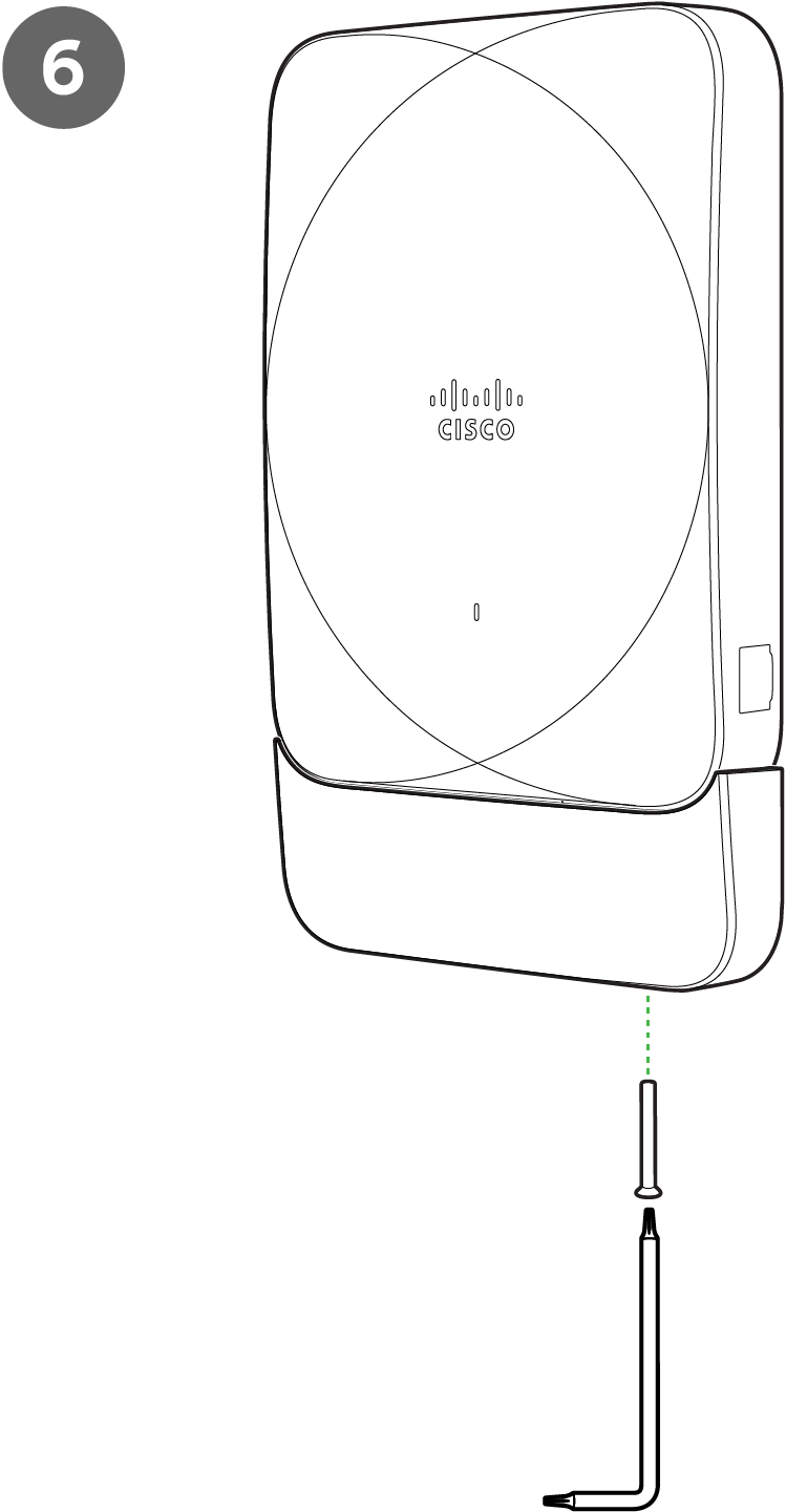_image.png?revision=1&size=bestfit&width=430&height=827)
_image.png?revision=1&size=bestfit&width=426&height=775)
Ejecting the CW9172H from the Port Lock Accessory
Use the Allen-Key tool to unscrew the 12mm torx screw on the left and 25mm torx screw on the right of the port cover.
_image.png?revision=1&size=bestfit&width=367&height=678)
_image.png?revision=1&size=bestfit&width=390&height=760)
After removing the screws, remove the front plate from the back plate. Remove the Ethernet cables.

Eject the CW9172H from the wall mount cradle.
_image.png?revision=1&size=bestfit&width=440&height=651)
_image.png?revision=1&size=bestfit&width=584&height=478)
Remove the Uplink Ethernet cable and unscrew to remove the wall mount cradle from the wall for junction box.
_image.png?revision=1&size=bestfit&width=491&height=342)
_image.png?revision=1&size=bestfit&width=423&height=360)
Install CW9172H with Desktop Mount Accessory
The CW-ACC-DESK1-00 is a desk mount accessory for the CW9172H Access Point. It is designed for situations where the CW9172H needs to be placed on a desk instead of mounted on a wall.
Package Contents

-
1x Desktop Cover
-
1x Desktop Base
-
1x Pass thru jumper cable
-
1x Security Allen-Key Tool
-
1x Security screw
-
1x Desktop K-lock bracket
-
1x Desktop K-lock screw
Installation Instructions
Use the pass through jumper cable and connect the Ethernet Port and Pass through Jumper port on the back side.

Aligning the top edge of the CW9172H AP to the Desktop cover, then adjust the CW9172H’s bottom slot into the Desktop cover’s bottom tab, until it clicks into one place.
_image.png?revision=1&size=bestfit&width=534&height=443)
_image.png?revision=1&size=bestfit&width=532&height=469)
Place the CW9172H unit along with the attached Desktop cover onto the desktop base.

To secure the CW9172H Access Point to the Desktop kit, use the Security 12mm torx and screw it.

To physically secure the Access Point, a Kensington lock attachment, consisting of the bracket and screw that comes with the accessory can be used to connect a Kensington Lock cable. Attach the bracket to the desktop cover and screw it.

The Kensington Lock cable now be attached to the bracket to secure the Access Point.

Connect the uplink cable to the pass through port and the local lan cables to the LAN Port.

Ejecting the CW9172H from the Desktop Cradle Accessory
Remove the Ethernet cables.

Unlock and remove the Kensington lock from the CW9172H Access Point.

Remove the Kensington lock attachment from the Desktop Cover.

Remove the security lock screw from the CW9172H Access Point using the Allen-Key Tool.

Remove the CW9172H along with the desktop cover from the desktop base.

Hold the CW9172H with one hand and use the eject tool to trigger the release mechanism. Detach the CW9172H from the desktop cover.
_image.png?revision=1&size=bestfit&width=540&height=465)
_image.png?revision=1&size=bestfit&width=530&height=608)
Unplug the Pass-through jumper cable from the Ethernet and Jumper port.

Powering the Access Point:
If mounting to an electrical junction box, feed the Ethernet cable through the cable access hole in the mount cradle. If mounting to a wall or ceiling, the Ethernet cable will feed on behind the AP. The "Power Source Options" section of this document lists the different powering options and their unique characteristics.
To attach the CW9172I AP to the universal mounting bracket properly, align the access point feet over the keyhole mounting slots on the mounting bracket. Since the cradle is already mounted to the wall, gently guide the CW9172I AP toward the mounting cradle until it clicks into place.
Verify Device Functionality and Test Network Coverage
-
Check LEDs
-
The Power LED should be solid green (or blue, if clients are connected). If it is flashing blue, the firmware is automatically upgrading and the LED should turn green when the upgrade is completed (normally within a few minutes). See the "LED Indicators" section for more details.
-
Note: Your AP must have an active route to the Internet to check and upgrade its firmware.
-
-
Verify access point connectivity
-
Use any 802.11 client device to connect to the AP and verify proper connectivity using the client’s web browser.
-
-
Check network coverage
-
Confirm that you have good signal strength throughout your coverage area. You can use the signal strength meter on a laptop, smartphone, or another wireless device.
Enable 802.11be
Enable 802.11be in the Meraki Dashboard to allow Wi-Fi 7 clients to connect with 11be rates or use Multi-Link Operation (MLO).
802.11be can be enabled from Wireless > Configure > Radio Settings>RF Profiles

320 MHz Channel Width
Wi-Fi 7 allows channel width of up to 320 MHz for 6 GHz Frequency band. This higher channel width helps to increase the overall throughput. In countries with support of 1200 MHz of 6 GHz Frequency spectrum, a total of 3 non-overlapping 320 MHz channels can be achieved, when the AP is operating in Low Power (LPi) Indoor Mode. When the AP is operating in Standard Power, only one 320 MHz channel can be achieved in the UNII-5 band. In countries with support of 500 MHz of 6 GHz Frequency spectrum, only one 320 MHz channel can be achieved.
Meraki Dashboard allows manual configuration of 320 MHz Channel Width.
320 MHz channel width can be enabled from
Wireless → Configure → Radio Settings → RF Profile → 6 GHz.
Change the Channel width setting to Manual to enable 320 MHz.

WPA3 Support:
Wi-Fi 7 requires the client to support WPA3 or OWE with Protected Management Frame (PMF) as a mandatory mode of operation for Wi-Fi 7 -i.e. for 11be rates and MLO. The Wi-Fi 7 Access Point is very much backward compatible with the earlier security mechanisms like WPA2, but when a Wi-Fi 7 client connects with a lower security type, it cannot achieve the Wi-Fi 7 functionality.
Wi-Fi 7 brings new AKM support for WPA3-SAE and new increased ciphers for Enhanced Open (OWE) and WPA3-SAE. The new AKM is SAE-EXT (AKM 24). The cipher needed for OWE and WPA3-SAE in Wi-Fi 7 is GCMP256
WPA3-SAE Configuration:
From the Wireless → Configure → Access Control → Security,
-
Enter the password for WPA3-Personal,
-
Select WPA3 as the Encryption,
-
802.11w as Required.
-
From Advanced WPA3 settings (Cipher and AKM suite settings), select SAE-EXT and GCMP 256.
_image.png?revision=1&size=bestfit&width=618&height=612)
OWE Configuration:
From the Wireless → Configure → Access Control → Security,
-
Select Opportunistic Wireless Encryption (OWE)
-
Select WPA3 as the Encryption,
-
802.11w as Required.
-
From Advanced WPA3 settings (Cipher and AKM suite settings), select the cipher as GCMP 256.
_image.png?revision=1&size=bestfit&width=612&height=594)
- If an SSID is configured to support WPA3 transition mode for Personal across all three frequency bands, then the 2.4 GHz and the 5 GHz frequency will broadcast the SSID with transition mode support. The SSID will not be broadcast in the 6 GHz mode
- Starting R31 software release, if an SSID is configured to support WPA3 transition mode for Enterprise across all three frequency bands, then the 2.4 GHz and the 5 GHz frequency will broadcast the SSID with transition mode support and the SSID will be broadcasted as WPA3 in the 6 GHz band.
- If the AP is broadcasting at least one of the SSIDs with a lower security type, then the AP will not broadcast 11be information in the Beacon and Probe Response and will function as 11ax.This behaviour is due to change in a future firmware upgrade.
Basic Troubleshooting
The following steps can be used for troubleshooting basic connectivity issues with your access point.
-
Reset the access point
-
Factory reset the access point by holding the factory reset button for 60 seconds
-
Try switching cables, or testing your cable on another device
If your access point still does not connect, the following instructions may be useful, depending on your issue.
Check Radio Functionality by Making the AP a Repeater
-
If your AP is acting as a gateway, disconnect the Ethernet cable from the LAN (while keeping the AP powered on). This will switch your AP into repeater mode. If no other gateways are within range, the AP will begin broadcasting an SSID appended with "-scanning". If you are able to connect to this SSID and go to my.meraki.com from your web browser, then your radio is working.
-
Physically place the repeater AP (AP with disconnected LAN) next to a working gateway AP.
-
Connect the power adapter or PoE. The radio and signal strength LEDs on the AP will turn solid green or blue once the access point boots up and detects the gateway.
-
The access point is now a repeater and will check into the Dashboard.
-
On the Wireless > Access Points page in the Dashboard, you will see the connectivity bar for the specific Repeater AP reflecting a light green color, which means the AP is a repeater. Gateway APs will reflect a dark green color in the connectivity bar and also will have the letter G (Gateway) on top of the AP symbol.
Check Ethernet Port Functionality by Connecting to the AP
-
Disable the Wireless adapter on your computer.
-
Make sure the Ethernet adapter on your device is set to obtain an IP address automatically via DHCP.
-
Connect your computer to the Ethernet port on the AP with an Ethernet cable.
-
The Ethernet LED on the AP should turn solid green or blue.
-
If the Ethernet LED does not turn solid green or blue, try swapping the cable. If the Ethernet port still does not turn green or blue, try the second Ethernet port, if the AP has one.
-
If the Ethernet LED does not turn solid green or blue, you may have a bad port on the AP. If this is the case, the AP signal LEDs will continue to scan.
-
Once the Ethernet LED turns solid green or blue, your computer should obtain an IP address from the AP via DHCP.
Check Static IP Address Configuration
-
If the AP has a static IP address, the green signal LEDs will begin to flash on and off and you will not receive an IP address via DHCP.
-
Disconnect the Ethernet cable from the AP.
-
Associate to the SSID being broadcasted by the AP. If there are no other APs in the network within range the SSID may be appended with "-scanning".
-
Go to my.meraki.com in your web browser.
-
The MAC address on the back of the access point should match the physical address value on the my.meraki.com Overview page.
-
Once you have verified that the MAC address is correct on the overview tab, click the tab Static IP configuration.
-
Enter the username (serial number on the back of the AP) which is case-sensitive and must include the dashes. (There is no password).
-
Make sure your AP is set to obtain a correct DHCP or static IP address configuration from your network.
Reference https://documentation.meraki.com/MR for additional information and troubleshooting tips.
If you are still experiencing hardware issues, please contact Cisco Meraki support by logging in to the Dashboard and using the Help option near the top of the page, then opening an email case or calling using the contact information on that page.
Warranty
Additional warranty information can be found on the CW9172H Datasheet or on the Warranty Returns (RMA) page of the Cisco Meraki website.
If your Cisco Meraki device fails and the problem cannot be resolved by troubleshooting, contact support to address the issue. Once support determines that the device is in a failed state, they can process an RMA and send out a replacement device free of charge. In most circumstances, the RMA will include a pre-paid shipping label so the faulty equipment can be returned.
In order to initiate a hardware replacement for non-functioning hardware that is under warranty, you must have access to the original packaging the hardware was shipped in. The original hardware packaging includes device serial number and order information and may be required for return shipping.
CW9172I devices have been tested and found to comply with the limits for a Class B digital device, pursuant to part 15 of the FCC rules. These limits are designed to provide reasonable protection against harmful interference in a residential installation. This equipment generates, uses, and can radiate radio frequency energy and, if not installed and used in accordance with the instructions, may cause harmful interference to radio communications. However, there is no guarantee that interference will not occur in a particular installation.
Support and Additional Information
If issues are encountered with device installation or additional help is required, contact Meraki Support by logging in to dashboard.meraki.com and opening a case by visiting the Get Help section.
-
The equipment is intended for industrial or other commercial activities.
-
The equipment is used in areas without exposure to harmful and dangerous production factors unless otherwise specified in the operational documentation and/or on the equipment labeling.
-
The equipment is not for domestic use. The equipment is intended for operation without the constant presence of maintenance personnel.
-
The equipment is subject to installation and maintenance by specialists with the appropriate qualifications, sufficient specialized knowledge, and skills.
-
Rules and conditions for the sale of equipment are determined by the terms of contracts concluded by Cisco or authorized Cisco partners with equipment buyers.
-
Disposal of a technical device at the end of its service life should be carried out in accordance with the requirements of all state regulations and laws.
-
Do not throw in the device with household waste. The technical equipment is subject to storage and disposal in accordance with the organization's disposal procedure.
-
The equipment should be stored in its original packaging in a room protected from atmospheric precipitation. The permissible temperature and humidity ranges during storage are specified in the Operation (Installation) Manual.
-
Transportation of equipment should be carried out in the original packaging in covered vehicles by any means of transport. The temperature and humidity during transportation must comply with the permissible established ranges of temperature and humidity during storage (in the off state) specified in the Operation Manual (Installation)
For additional information on Meraki hardware and for other installation guides, refer to documentation.meraki.com.