
MR56 Installation Guide
The Cisco Meraki MR56 is dual-band enterprise-class 802.11ax cloud-managed access points. Designed for the highest capacity and highest density, MR56 meets the needs of the most demanding environments. The access point also includes a third radio dedicated to optimizing the RF environment and securing the airwaves.
About this Guide
This guide provides instructions on how to install and configure your MR56 access points. This guide also provides mounting instructions and limited troubleshooting procedures. For more wireless installation guides, refer to the wireless installation guides section on our documentation website.
Product Overview
Physical Specifications
| MR56 |
|
Interfaces
|
|
Power
Note: Actual power consumption may vary depending on the AP usage. |
|
Environment
|
|
Physical Security
|
Product View and Physical Features
Your MR56 has the following features:
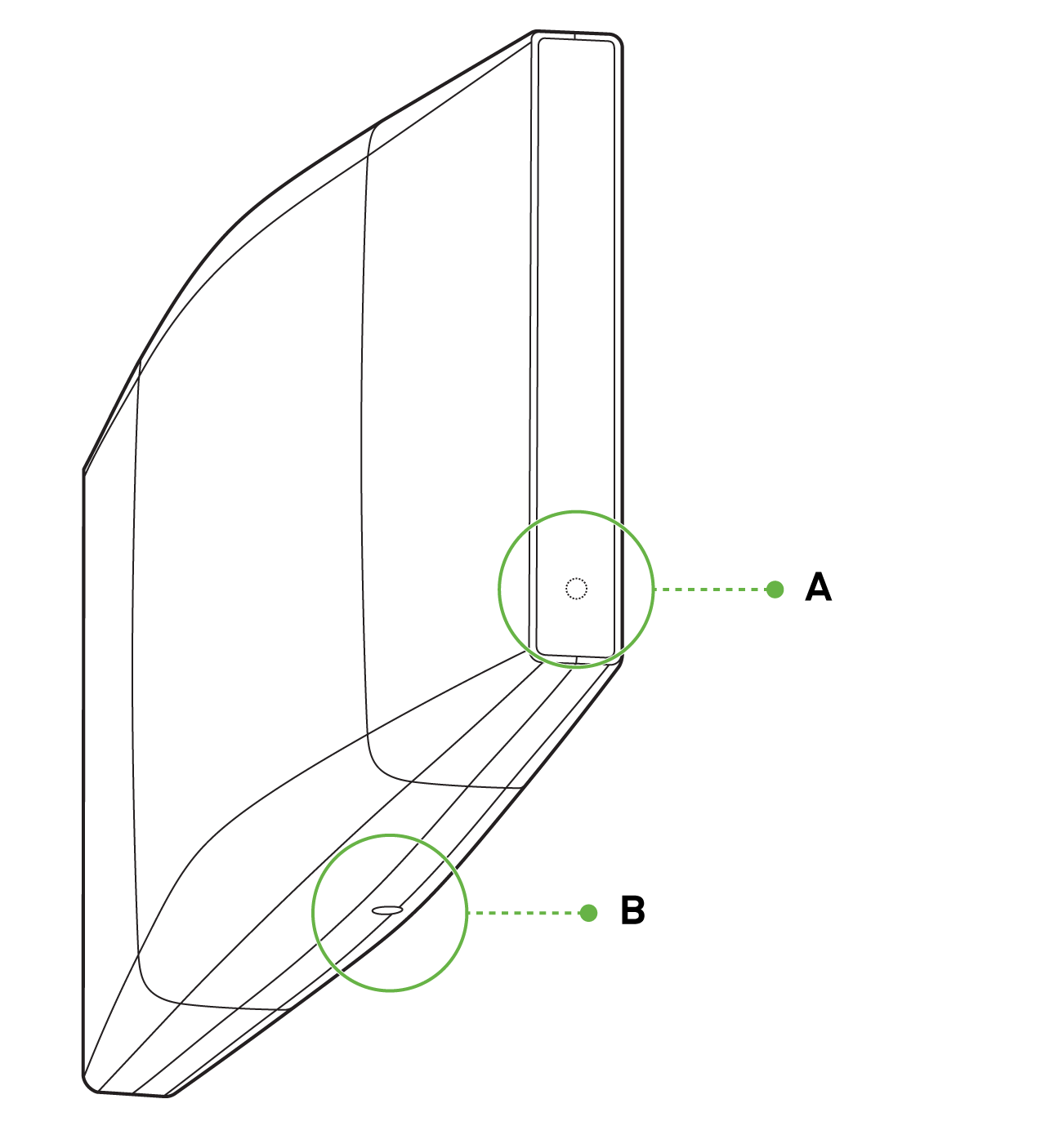


A - LED indicator
B - Security screw hole
C - Kensington lock hard point
D - Desk Mount feet
E - Mount cradle attachment point
F - Cable access bay
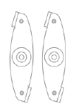
The mount cradle has the following features:

A - Cable access slot
B - Level tool
C - Mounting tab
Security Features
The MR56 features multiple options for physically securing the access point after installation:
-
Security screw – The accessory kit includes screws that can be used to secure the access point to the mount cradle. Engaging the security screw prevents accidental dislodging and theft.
-
Kensington lock – The access point contains a hard point that allows it to be secured to any nearby permanent structure using a standard Kensington lock.
Ethernet Ports
The MR56 features an Ethernet RJ45 port that accepts 802.3at power (labeled “Eth0, PoE”). This port should be used for uplink to your upstream network.

Power Source Options
The MR56 access point can be powered using either the Meraki AC Adapter, PoE Injector (both sold separately), or a PoE switch.
Factory Reset Button
If the button is pressed and held for at least five seconds and then released, the AP will reboot and be restored to its original factory settings by deleting all configuration information stored on the unit.
LED Indicators and Run Dark Mode
Your access point is equipped with a multi-color LED light on the front of the unit to convey information about system functionality and performance:
- Orange - AP is booting (permanent Orange suggests hardware issue)
- Rainbow - AP is initializing/scanning
- Blinking Blue - AP is upgrading
- Green - AP in Gateway mode with no clients
- Blue - AP in Gateway mode with clients
- Blinking Orange - AP can't find uplink
NOTE: Blinking Green LED indicates that the device is in site survey mode. Please see the Conducting Site Surveys with MR Access Points for more details.
The MR56 access point may be operated in the “Run Dark” mode for additional security and to reduce the visibility of the access point. In this mode, the LED will not be illuminated. This mode may be enabled through the Meraki Dashboard.
Package Contents
The access point packages contain the following:
MR56 Cloud-Managed Access Point

Mount cradle including built-in level tool

Drop ceiling mount kit

Wall screws, wall screw anchors, and security screws

Safety and Warnings
These operations are to be taken with respect to all local laws. Please take the following into consideration for safe operation:
- Power off the unit before you begin. Read the installation instructions before connecting the system to the power source.
- Before you work on any equipment, be aware of the hazards involved with electrical circuitry, and be familiar with standard practices for preventing accidents.
- Read the wall-mounting instructions carefully before beginning installation. Failure to use the correct hardware or to follow the correct procedures could result in a hazardous situation to people and damage to the system.
- This product relies on the building’s installation for short-circuit (overcurrent) protection. Ensure that the protective device is rated not greater than 15 A, 125 Vac, or 10A, 240 Vac.
- Please only power the device with the provided power cables or standard PoE to ensure regulatory compliance.
Pre-install Preparation
You should complete the following steps before going on-site to perform an installation.
Configure your Dashboard Network
The following is a brief overview only of the steps required to add an access point to your network. For detailed instructions about creating, configuring and managing Meraki wireless networks, refer to the online documentation (documentation.meraki.com).
- Login to http://dashboard.meraki.com. If this is your first time, create a new account.
- Find the network to which you plan to add your APs or create a new network.
- Add your APs to your network. You will need your Meraki order number (found on your invoice) or the serial number of each AP, which looks like Qxxx-xxxx-xxxx, and is found on the bottom of the unit. You will also need your license key, which you should have received via email.
- Go to the map / floor plan view and place each AP on the map by clicking and dragging it to the location where you plan to mount it.
Check and Set Firmware
To ensure your access point performs optimally immediately following installation, it is recommended that you facilitate a firmware upgrade prior to mounting your AP.
- Attach your AP to power and a wired Internet connection. See the "Getting Power to the AP" section for details.
- The AP will turn on and the LED will glow solid orange. If the unit does not require a firmware upgrade, the LED will turn either green (no clients associated) or blue (clients associated) within thirty seconds.
* If the unit requires an upgrade, the LED will begin blinking orange until the upgrade is complete, at which point the LED will turn solid green or blue. You should allow at least a few minutes for the firmware upgrade to complete, depending on the speed of your internet connection.
Check and Configure Upstream Firewall Settings
If a firewall is in place, it must allow outgoing connections on particular ports to particular IP addresses. The most current list of outbound ports and IP addresses for your particular organization can be found on the firewall configuration page in your dashboard.
Assigning an IP Address
All gateway APs (An AP with Ethernet connections to the LAN) must be assigned routable IP addresses. These IP addresses can be dynamically assigned via DHCP or statically assigned.
Dynamic Assignment
- When using DHCP, the DHCP server should be configured to assign a static IP address for each MAC address belonging to a Meraki AP. Other features of the wireless network, such as 802.1X authentication, may rely on the property that the APs have static IP addresses.
Static Assignment
- Static IPs are assigned using the local web server on each AP. The following procedure describes how to set the static IP:
- Using a client machine (e.g., a laptop), connect to the AP wirelessly (by associating to any SSID broadcast by the AP) or over a wired connection.
- If using a wired connection, connect the client machine to the AP either through a PoE switch or a PoE Injector. If using a PoE switch, plug an Ethernet cable into the AP’s Ethernet jack, and the other end into a PoE switch. Then connect the client machine over Ethernet cable to the PoE switch. If using a PoE Injector, connect the AP to the “PoE” port of the Injector, and the client machine to the “LAN” port.
- Using a web browser on the client machine, access the AP’s built-in web server by browsing to http://my.meraki.com. Alternatively, browse to http://10.128.128.128.
- Click on the “Uplink Configuration” tab. Log in. The default login is the serial number (e.g. Qxxx-xxxx-xxxx), with no password (e.g., Q2DD-551C-ZYW3).
- Configure the static IP address, net mask, gateway IP address and DNS servers that this AP will use on its wired connection.
- If necessary, reconnect the AP to the LAN.
Static IP via DHCP Reservations
- Instead of associating to each Meraki AP individually to configure static IP addresses, an administrator can assign static IP addresses on the upstream DHCP server. Through “DHCP reservations,” IP addresses are “reserved” for the MAC addresses of the Meraki APs. Please consult the documentation for the DHCP server to configure DHCP reservations.
Collect Tools
You will need the following tools to perform an installation:
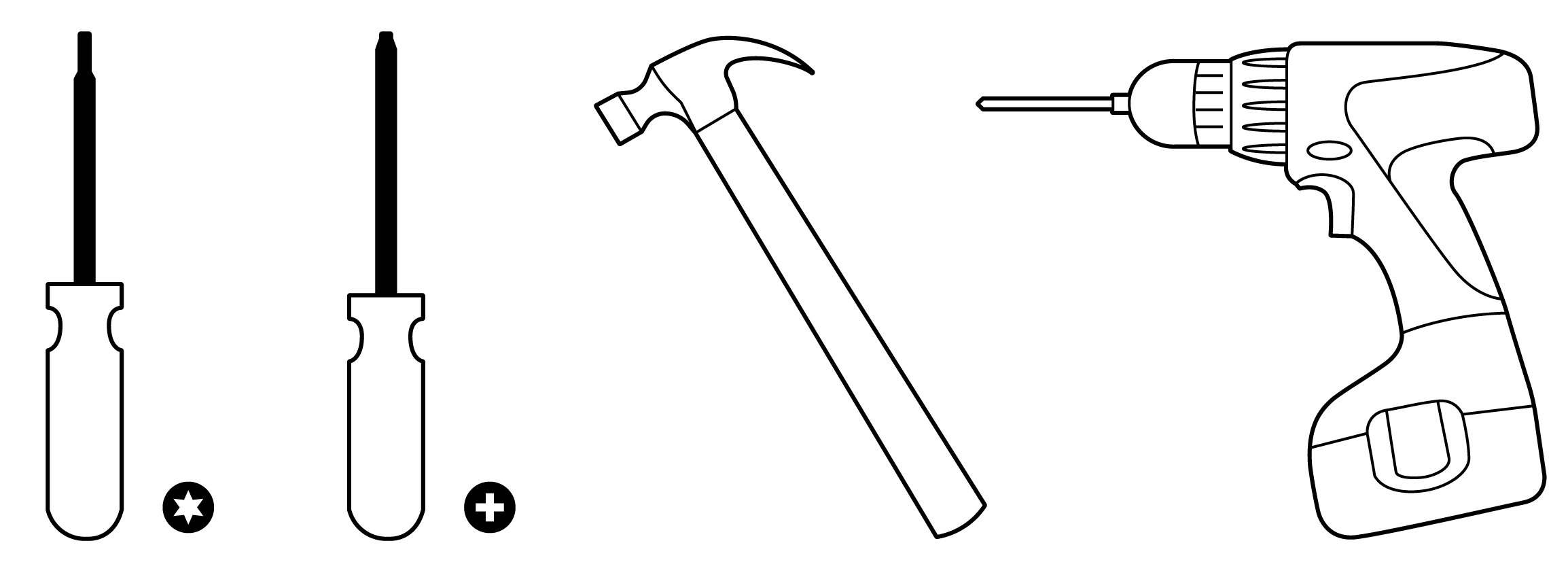
T8 Torx Screwdriver, Phillips screwdriver, Hammer, Drill with 1/4" (6.3mm) bits
Collect Additional Hardware for Installation
You will need the following hardware to perform an installation:

802.3at PoE Power Source (either PoE switch or Meraki 802.3at PoE Injector) or an AC adaptor and network cables with RJ45 connectors long enough for your particular mounting location
Installation Instructions
Warning: Due to the heat dissipation in the back of APs during normal operation, please do not stack powered on APs on top of each other during pre-installation to avoid heat damage.
Choose Your Mounting Location
A good mounting location is important to get the best performance out of your access point. Keep the following in mind:
- The device should have an unobstructed line of sight to most coverage areas. For example, if installing in an office filled with workspaces divided by mid-height cubicle walls, installing on the ceiling or high on a wall would be ideal.
- Power over Ethernet supports a maximum cable length of 300 ft (100 m).
- If being used in a mesh deployment, the AP should have a line of sight to at least two other Meraki devices. A Cisco Partner can help ensure that your AP placement is ideal.
Install the AP
For most mounting scenarios, the access point mount cradle provides a quick, simple, and flexible means of mounting your device. The installation should be done in two steps. First, install the mount cradle to your selected location. Then, attach the AP to the mount cradle.
Attach the Mount Cradle
The access point mount cradle can be used to install your access point in a wide range of scenarios: wall or solid ceiling, below a drop ceiling, on various electrical junction boxes.
The mount cradle contains a variety of hole patterns that are customized for each installation scenario. The mounting template (included inbox with mount cradle) should be used to drill holes for wall mounts and also to identify the correct hole patterns in the mount cradle that should be used for each type of mount. The included mount cradle template shows the hole patterns that should be used for each type of mount.
Wall or Solid Ceiling Mount Using Mount Cradle
Using included wall anchors and screws, attach the mount cradle to your mounting wall or ceiling. It is recommended that the AP be mounted to a wall or solid ceiling using the mount cradle for physical security reasons.
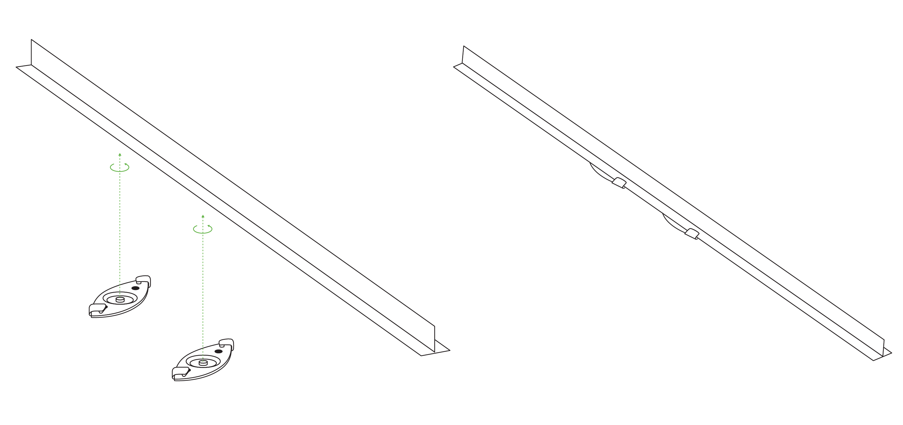
Drop Ceiling Mount using Mount Cradle
To mount your AP on a drop ceiling T-rail, use the included drop ceiling mounting accessory kit. The accessory kit can be used to mount to most 9/16”, 15/16” or 1 ½” T-rails. The kit contains:
Drop ceiling mounting clips with set screws
6-32x4 mm screws

6-32x7 mm screws only used for recessed rail mount

2 rubber spacers

- Attach the T-rail clips to the T-rail by rotating them and snapping them into place as shown. The black foam pads should be compressed slightly after installation.

- Using the dashed lines on the mount cradle template as a guide, set the proper spacing of the T-rail clips on the T-rail.
- Tighten the set screws on the T-rail clips to secure the clips using a 5/64”(2 mm) hex key.
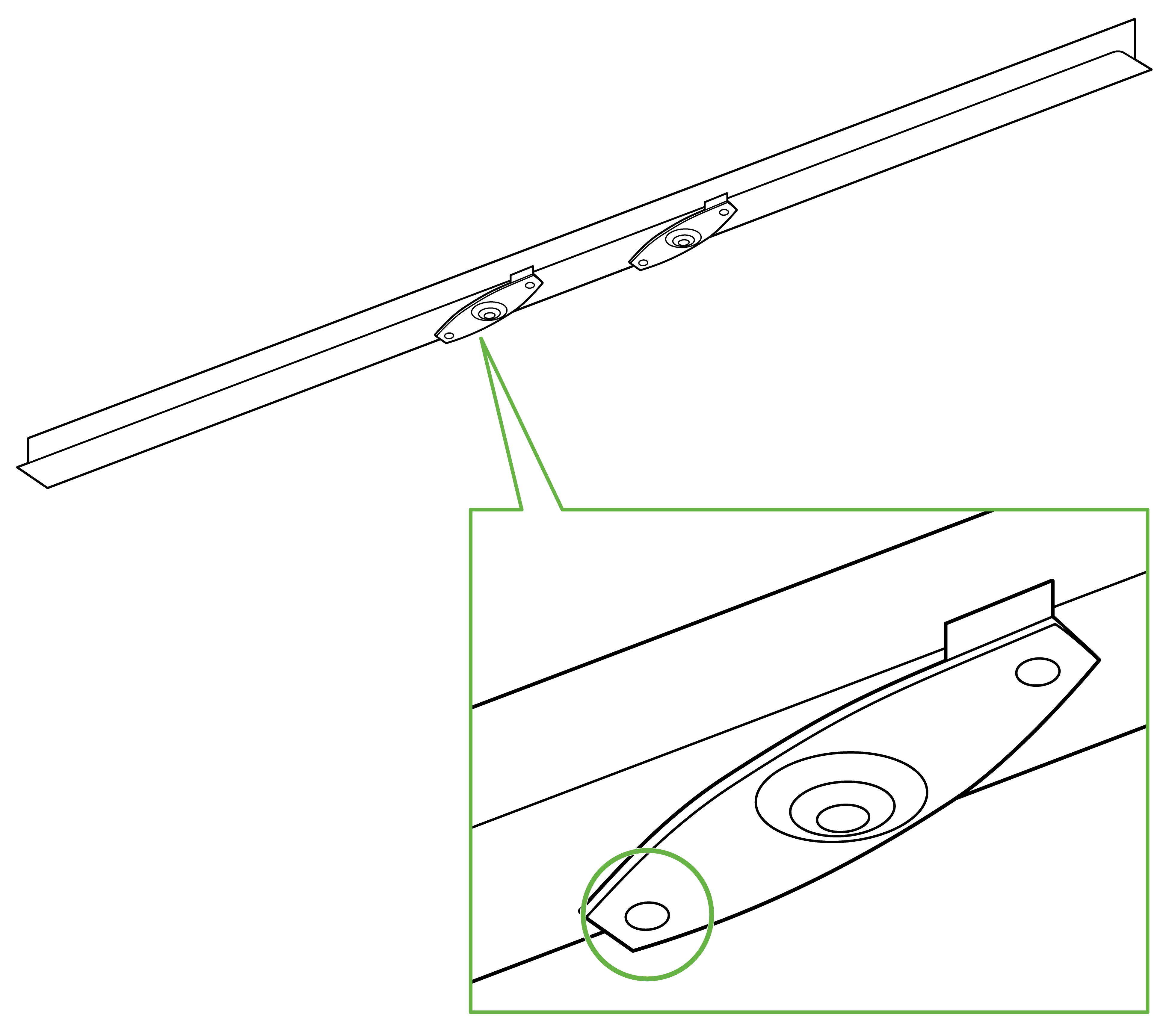
[One of four set screws indicated]
- Attach the mount cradle to the T-rail clips using the mount cradle holes (marked with a “T“).
Tip: Pre-assemble rubber spacers and screws to the mount cradle. The mount cradle can then be held with one hand while the other hand holds a screwdriver. If mounting your AP to a dropped ceiling, skip to the "Getting Power to the AP" section.
Electrical Junction Box Mount Using Mount Cradle
The access point can be mounted to a 4” square cable junction box, a 3.5 or 4” round cable junction box, or various U.S. and European outlet boxes (mounting screws are not included).
Using appropriate mounting hardware for your specific type of junction box, attach the mount cradle to the junction box.
Getting Power to the AP
If mounting to an electrical junction box, feed the Ethernet cable through the cable access hole in the mount cradle. If mounting to a wall or ceiling, the Ethernet cable will feed from behind the AP. The "Power Source Options" section of this document lists the different powering options and their unique characteristics.
Mount the AP
Attach the MR56 AP to the Mount Cradle
(This section applies to wall and/or solid ceiling, drop ceiling, or electrical junction box mount where you have already installed the mount cradle.)
The MR56 AP attaches to the mount cradle with two tabs on the cradle that insert into the MR56 AP and is secured to the cradle using one screw.
To attach the MR56 AP to the mount cradle properly, line up the top edge of the AP with the top tab of the mount cradle. Since the cradle is already mounted to the wall, guide the MR56 AP towards the top tab, and insert the top tab into the MR56 AP’s slot.

Then adjust the MR56 AP to guide the AP’s bottom slot into the cradle’s bottom tab until it clicks into place. Once in place, the MR56 AP should be secured to the cradle by using one of the included screws in the cradle’s bottom tab.

To release the AP from the mount cradle, first remove the security screw that secures the MR56 AP to the cradle’s bottom tab. While holding the MR56 AP with one hand, press the cradle’s bottom tab upwards, releasing the MR56 AP from the bottom of the cradle. Then remove the MR56 AP from the cradle’s top tab.
Desk or Shelf Mount
The access point can both be placed on a desk or shelf resting on the non-scratch rubber feet. The mount cradle is not necessary for a desk or shelf installation.
Physical Security
Depending on your mounting environment, you may want to secure the AP to its mount location. The access point can both be secured in several ways. If the AP has been installed using the mount cradle, it should be secured via security screw (Torx security screws are included) and/or Kensington lock. If the mount cradle was not used, the AP can still be secured using a Kensington lock.
Security Screw
The accessory kit includes screws that can be used to secure the access point to the mount cradle. Engaging the security screw prevents accidental dislodging and theft.
Kensington Lock
The access point contains a hard point that allows it to be secured to any nearby permanent structure using a standard Kensington lock. Attach a Kensington lock cable to the access point at the hard point on the side of the device. Attach the other end of the cable to a secure location, such as a pipe or building fixture.
Verify Device Functionality and Test Network Coverage
- Check LEDs
- The Power LED should be solid green (or blue, if clients are connected). If it is flashing blue, the firmware is automatically upgrading and the LED should turn green when the upgrade is completed (normally within a few minutes). See the "LED Indicators" section for more details. .
- Note: Your AP must have an active route to the Internet to check and upgrade its firmware.
- Verify access point connectivity
- Use any 802.11 client device to connect to the AP and verify proper connectivity using the client’s web browser.
- Check network coverage
- Confirm that you have good signal strength throughout your coverage area. You can use the signal strength meter on a laptop, smartphone, or another wireless device.
Basic Troubleshooting
The following steps can be used for troubleshooting basic connectivity issues with your access point.
- Reset the access point
- Factory reset the access point by holding the factory reset button for 5 seconds
- Try switching cables, or testing your cable on another device
If your access point still does not connect, the following instructions may be useful, depending on your issue.
Check Radio Functionality by Making the AP a Repeater
- If your AP is acting as a gateway, disconnect the Ethernet cable from the LAN (while keeping the AP powered on). This will switch your AP into repeater mode. If no other gateways are within range, the AP will begin broadcasting an SSID appended with "-scanning". If you are able to connect to this SSID and go to my.meraki.com from your web browser, then your radio is working.
- Physically place the repeater AP (AP with disconnected LAN) next to a working gateway AP.
- Connect the power adapter or PoE. The radio and signal strength LEDs on the AP will turn solid green or blue once the access point boots up and detects the gateway.
- The access point is now a repeater and will check into the Dashboard.
- On the Wireless > Access Points page in the Dashboard, you will see the connectivity bar for the specific Repeater AP reflecting a light green color, which means the AP is a repeater. Gateway APs will reflect a dark green color in the connectivity bar and also will have the letter G (Gateway) on top of the AP symbol.
Check Ethernet Port Functionality by Connecting to the AP
- Disable the Wireless adapter on your computer.
- Make sure the Ethernet adapter on your device is set to obtain an IP address automatically via DHCP.
- Connect your computer to the Ethernet port on the AP with an Ethernet cable.
- The Ethernet LED on the AP should turn solid green or blue.
- If the Ethernet LED does not turn solid green or blue, try swapping the cable. If the Ethernet port still does not turn green or blue, try the second Ethernet port, if the AP has one.
- If the Ethernet LED does not turn solid green or blue, you may have a bad port on the AP. If this is the case, the AP signal LEDs will continue to scan.
- Once the Ethernet LED turns solid green or blue, your computer should obtain an IP address from the AP via DHCP.
Check Static IP Address Configuration
- If the AP has a static IP address, the green signal LEDs will begin to flash on and off and you will not receive an IP address via DHCP.
- Disconnect the Ethernet cable from the AP.
- Associate to the SSID being broadcasted by the AP. If there are no other APs in the network within range the SSID may be appended with "-scanning".
- Go to my.meraki.com in your web browser.
- The MAC address on the back of the access point should match the physical address value on the my.meraki.com Overview page.
- Once you have verified that the MAC address is correct on the overview tab, click the tab Static IP configuration.
- Enter the username (serial number on the back of the AP) which is case sensitive and must include the dashes. (There is no password).
- Make sure your AP is set to obtain a correct DHCP or static IP address configuration from your network.
Reference https://documentation.meraki.com/MR for additional information and troubleshooting tips.
If you are still experiencing hardware issues, please contact Cisco Meraki support by logging in to the Dashboard and using the Help option near the top of the page, then opening and email case or calling using the contact information on that page.
Warranty
Additional warranty information can be found on the MR56 Datasheet or on the Warranty Returns (RMA) page of the Cisco Meraki website.
If your Cisco Meraki device fails and the problem cannot be resolved by troubleshooting, contact support to address the issue. Once support determines that the device is in a failed state, they can process an RMA and send out a replacement device free of charge. In most circumstances, the RMA will include a pre-paid shipping label so the faulty equipment can be returned.
In order to initiate a hardware replacement for non-functioning hardware that is under warranty, you must have access to the original packaging the hardware was shipped in. The original hardware packaging includes device serial number and order information and may be required for return shipping.
Meraki MR56 devices have been tested and found to comply with the limits for a Class B digital device, pursuant to part 15 of the FCC rules. These limits are designed to provide reasonable protection against harmful interference in a residential installation. This equipment generates, uses and can radiate radio frequency energy and, if not installed and used in accordance with the instructions, may cause harmful interference to radio communications. However, there is no guarantee that interference will not occur in a particular installation.
Support and Additional Information
If issues are encountered with device installation or additional help is required, contact Meraki Support by logging in to dashboard.meraki.com and opening a case by visiting the Get Help section.
- The equipment is intended for industrial or other commercial activities.
- The equipment is used in areas without exposure to harmful and dangerous production factors unless otherwise specified in the operational documentation and/or on the equipment labeling.
- The equipment is not for domestic use. The equipment is intended for operation without the constant presence of maintenance personnel.
- The equipment is subject to installation and maintenance by specialists with the appropriate qualifications, sufficient specialized knowledge, and skills.
- Rules and conditions for the sale of equipment are determined by the terms of contracts concluded by Cisco or authorized Cisco partners with equipment buyers.
- Disposal of a technical device at the end of its service life should be carried out in accordance with the requirements of all state regulations and laws.
- Do not throw in the device with household waste. The technical equipment is subject to storage and disposal in accordance with the organization's disposal procedure.
- The equipment should be stored in its original packaging in a room protected from atmospheric precipitation. The permissible temperature and humidity ranges during storage are specified in the Operation (Installation) Manual.
- Transportation of equipment should be carried out in the original packaging in covered vehicles by any means of transport. The temperature and humidity during transportation must comply with the permissible established ranges of temperature and humidity during storage (in the off state) specified in the Operation Manual (Installation)
For additional information on Meraki hardware and for other installation guides, please refer to documentation.meraki.com.