
Wi-Fi 6 (802.11ax) Technical Guide
Click 日本語 for Japanese
Overview
When Wi-Fi entered the marketplace, it evolved rapidly to meet the needs of its users. Each successive IEEE 802.11 standard aimed to provide higher throughput. While the IEEE 802.11ax standard provides greater throughput than previous standards, its true focus is to improve wireless efficiency.
To learn more about the need for Wi-Fi 6, check out our Wi-Fi 6 whitepaper. This document explores the main features of Wi-Fi 6 and how they work on Cisco Meraki access points.
Wi-Fi 6 or 802.11ax?
With the coming of 802.11ax, the Wi-Fi Alliance has introduced a Wi-Fi generation numbering scheme to simplify how the industry differentiates Wi-Fi technologies and increase user awareness of the features available with different standards. Rather than memorizing each IEEE 802.11 amendment, each standard may be referred to as "Wi-Fi," followed by a generation number.
Wi-Fi 6 and 802.11ax represent the newest wireless standard, however the terms are not interchangeable. Not every feature available in the IEEE 802.11.ax standard is required for the Wi-Fi Alliance's Wi-Fi 6 certification.
|
Wi-Fi Generation |
IEEE Standard |
Year Ratified |
|
Wi-Fi 4 |
802.11n |
2009 |
|
Wi-Fi 5 |
802.11ac |
2014 |
|
Wi-Fi 6 |
802.11ax |
2021 |
802.11ax Feature Overview
The following table compares 802.11ax to the previous two standards. These features and their abbreviations will be further explored later in this document.
|
Capabilities |
802.11n |
802.11ac |
802.11ax |
|
Physical Layer (PHY) |
High Throughput (HT) |
Very High Throughput (VHT) |
High-Efficiency Wireless (HEW) |
|
Operating Bands |
2.4 and 5 GHz |
5 GHz only |
2.4 and 5 GHz |
|
MU-MIMO |
N/A |
DL MU-MIMO only |
DL and UL MU-MIMO |
|
Channel Width |
20, 40, 80 MHz |
20, 40, 80, 80+80, 160 MHz |
20, 40, 80, 80+80, 160 MHz |
|
Guard Interval |
800/400 ns |
800/400 ns |
800/1600/3200 ns |
|
Spread Spectrum Technology |
OFDM |
OFDM |
OFDM, OFDMA |
|
Frequency Modulation |
64 QAM |
256 QAM |
1024 QAM with MCS 10, 11 |
|
Power Save |
STBC, U-APSD |
STBC, U-APSD |
STBC, U-APSD, TWT |
|
Spectral Efficiency |
N/A |
N/A |
BSS Coloring |
Cisco Meraki 802.11ax Access Points
Compatible vs. Certified
Early Meraki 802.11ax access points (APs), such as the MR45/55, are 802.11ax compatible but are not WiFi 6 certified. APs that are compatible support some, but not all, 802.11ax features.
The following table displays the 802.11ax features available with Cisco Meraki APs. More information about specific Meraki AP models is available on our website.
Indoor APs
|
Capabilities |
MR44 |
MR45 |
MR55 |
MR36 |
MR46 |
MR56 |
|
802.11ax Compliance |
Compatible |
Compatible |
Compatible |
Compatible | Compatible | Compatible |
| Wi-Fi 6-Certified | Certified | - | - | Certified | Certified | Certified |
|
2.4 GHz Radio Information |
802.11b/g/n/ax 2x2:2 |
802.11b/g/n/ax 4x4:4 |
802.11b/g/n/ax 4x4:4 |
802.11b/g/n/ax 2x2:2 |
802.11b/g/n/ax 4x4:4 |
802.11b/g/n/ax 4x4:4 |
|
5 GHz Radio Information |
802.11a/n/ac/ax 4x4:4 |
802.11a/n/ac/ax 4x4:4 |
802.11a/n/ac/ax 8x8:8 |
802.11a/n/ac/ax 2x2:2 |
802.11a/n/ac/ax 4x4:4 |
802.11a/n/ac/ax 8x8:8 |
|
MIMO |
SU-MIMO, UL MU-MIMO*, and DL MU-MIMO support |
SU-MIMO, DL |
SU-MIMO, DL |
SU-MIMO, UL MU-MIMO*, |
SU-MIMO, |
SU-MIMO, UL MU-MIMO*, DL MU-MIMO |
|
Channel Widths (MHz) |
20, 40, 80 |
20, 40, 80 |
20, 40, 80 |
20, 40, 80 |
20, 40, 80 |
20, 40, 80 |
|
OFMDA |
DL, UL |
DL only |
DL only |
DL, UL |
DL, UL |
DL, UL |
|
Frequency Modulation |
Up to 1024-QAM with MCS 10, 11 |
Up to 1024 QAM with MCS 10, 11 |
Up to 1024 QAM with MCS 10, 11 |
Up to 1024 QAM with MCS 10, 11 |
Up to 1024 QAM with MCS 10, 11 |
Up to 1024 QAM with MCS 10, 11 |
|
Maximum Data Rate |
combined dual–radio aggregate frame rate of 3 Gbps**, with up to 2,402 Mbps in the 5 GHz band and 573 Mbps in the 2.4 GHz |
3.5 Gbps |
5.9 Gbps |
combined dual–radio aggregate frame rate of 1.7 Gbps**, with up to 1,201 Mbps in the 5 GHz band and 573 Mbps in the 2.4 GHz band |
combined dual–radio aggregate frame rate of 3.5 Gbps**, with up to 2,402 Mbps in the 5 GHz band and 1,147 Mbps in the 2.4 GHz band |
combined dual–radio aggregate frame rate of 5.9 Gbps**, with up to 4,804 Mbps in the 5 GHz band and 1,147 Mbps in the 2.4 GHz band |
|
Power Save |
STBC, U-APSD, TWT* |
STBC, U-APSD, TWT* |
STBC, U-APSD, TWT* |
STBC, U-APSD, TWT* |
STBC, U-APSD, TWT* |
STBC, U-APSD, TWT* |
|
Spectral Efficiency |
BSS Coloring* |
BSS Coloring* |
BSS Coloring* |
BSS Coloring* |
BSS Coloring* |
BSS Coloring* |
|
RJ45 Ethernet Port |
1x 100/1000/2.5G BASE-T Ethernet (RJ45) |
1x 10/100/1000/2.5G BASE-T Ethernet (RJ45) |
1x 10/100/1000/2.5G/5G BASE-T Ethernet (RJ45) |
1x 10/100/1000 BASE-T Ethernet (RJ45) |
1x 10/100/1000/2.5G BASE-T Ethernet (RJ45)
|
1x 10/100/1000/2.5G/5G BASE-T Ethernet (RJ45)
|
* Feature available with a firmware upgrade.
** Refers to maximum over-the-air data frame-rate capability of the radio chipset, and may exceed data rates allowed by IEEE 802.11ax operation.
Outdoor APs
|
Capabilities |
MR76 | MR86 |
|
802.11ax Compliance |
Compatible |
Compatible |
| Wi-Fi 6 Certified | Certified | Certified |
|
2.4 GHz Radio Information |
802.11a/n/ac/ax 2x2:2 | 802.11b/g/n/ax 4x4:4 |
|
5 GHz Radio Information |
802.11a/n/ac/ax 2x2:2 | 802.11a/n/ac/ax 4x4:4 |
|
MIMO |
SU-MIMO, UL MU-MIMO*, DL MU-MIMO | SU-MIMO, UL MU-MIMO*, DL MU-MIMO |
|
Channel Widths (MHz) |
20, 40, 80 | 20, 40, 80 |
|
OFMDA |
DL, UL | DL, UL |
|
Frequency Modulation |
Up to 1024 QAM with MCS 10, 11 | Up to 1024 QAM with MCS 10, 11 |
|
Maximum Data Rate |
combined dual–radio aggregate frame rate of 1.7 Gbps*, with up to 1,201 Mbps in the 5 GHz band and 573 Mbps in the 2.4 GHz | combined dual–radio aggregate frame rate of 3.5 Gbps*, with up to 2,402 Mbps in the 5 GHz band and 1,148 Mbps in the 2.4 GHz |
|
Power Save |
STBC, U-APSD, TWT* | STBC, U-APSD, TWT* |
|
Spectral Efficiency |
BSS Coloring* | BSS Coloring* |
|
RJ45 Ethernet Port |
1x 10/100/1000 BASE-T Ethernet (RJ45) |
1x 100/1000/2.5G BASE-T Ethernet (RJ45) |
* Feature available with a firmware upgrade.
** Refers to maximum over-the-air data frame-rate capability of the radio chipset, and may exceed data rates allowed by IEEE 802.11ax operation.
Wi-Fi 6 Features
Orthogonal frequency division multiple access (OFDMA)
Wi-Fi 6 uses a combination of two modulation methods: orthogonal frequency division multiplexing (OFDM) and orthogonal frequency division multiple access (OFDMA).
OFDMA is introduced in the 802.11ax standard for data transmissions. While OFDM is used in previous standards, it continues to be used in 802.11ax for management and control frames in order to maintain backward compatibility with legacy devices.
The sections ahead will examine what makes OFDMA unique from OFDM. As they make comparisons, bear in mind the following equation for calculating the maximum PHY throughput.

Subcarriers
In OFDM, each channel is made up of many smaller channels known as subcarriers or tones.

When a device transmits using OFDM, it transmits data on the subcarriers in parallel, using multiple smaller sub-signals instead of one large signal over the entire channel, improving signal efficiency and resilience.
There are three different types of subcarriers:
-
Data subcarriers: used to transmit data
-
Pilot subcarriers: used for synchronization between sender and receiver
-
Guard subcarriers: used to avoid interference
The concept of subcarriers is the same in OFDMA, however, OFDMA subcarriers are spaced four times closer together to make room for four times as many subcarriers. OFDM uses 64 subcarriers spaced 312.5 KHz apart. OFDMA uses 256 subcarriers spaced 78.125 KHz apart.
Symbol Time
Each stream of data transmitted on the subcarriers is made up of a series of modulated wave patterns called symbols. Each symbol represents a set of 1s and 0s through a process called Quadrature Amplitude Modulation. To learn more about modulation, check out our article on 802.11 Fundamentals: Modulation.
The amount of time it takes to transmit each symbol is called the symbol time. OFDM symbols take 3.2 µs. OFDMA symbols take four times longer, 12.8 µs. The longer symbols provide the time needed to make other beneficial features like MU-OFDMA possible.
Multiuser OFDMA (MU-OFDMA)
If multiple wireless devices transmit on the same channel at the same time, the signals may collide and interfere with each other. When this happens, the devices must wait for another opportunity to transmit (TXOP) and try again. To avoid interfering with each other, devices take turns using the channel. The following diagram demonstrates what this process looks like with OFDM.
_per_client_depiction.png?revision=1)
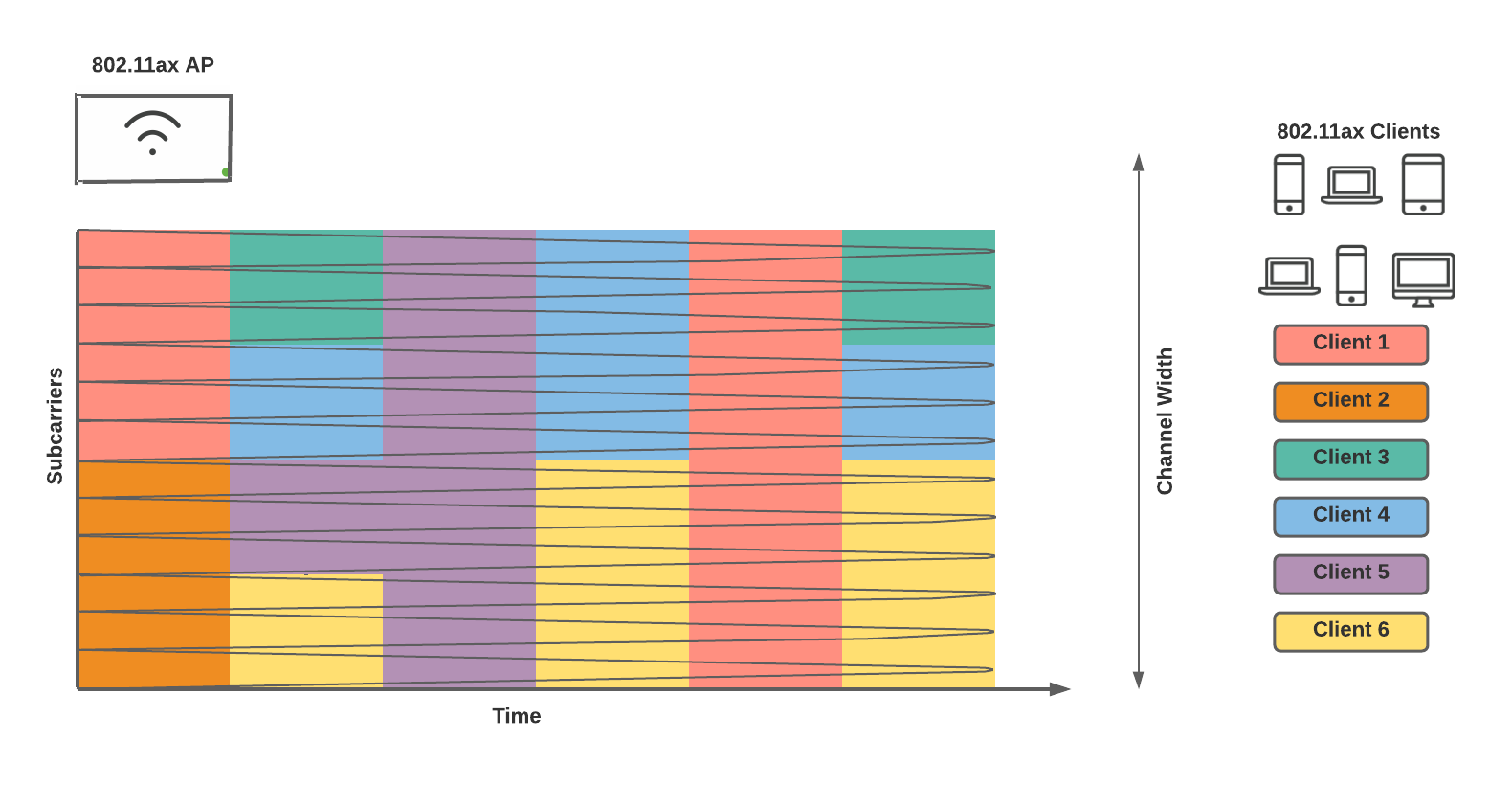
When OFDMA is in use, an 802.11ax AP can allot groups of subcarriers to different devices so communication can take place in parallel. This aspect of OFDMA is known as multiuser OFDMA (MU-OFDMA).
At each TXOP, an 802.11ax AP decides how many subcarriers to allot to each client station (STA) based on their bandwidth needs. The goal is to achieve the highest airtime efficiency possible. At one TXOP, multiple STAs may share the subcarriers and transmit simultaneously. At another TXOP, a single STA may be assigned to all subcarriers.
The following diagram shows what the subcarrier usage might look like over time using OFDMA.
_per_client_depiction_802.11ax.png?revision=1)
Resource Units (RUs)
In OFDMA, the groups of subcarriers assigned to client STAs are called resource units (RUs).
RUs can consist of as few as 26 subcarriers, totaling 2 MHz, to all subcarriers in the channel. The following diagram shows the different possible RU sizes for a 20 MHz channel.

As seen in the max PHY throughput equation, increasing the number of available subcarriers increases the total throughput. Therefore, larger RUs provide more throughput than smaller RUs. However, larger RUs leave fewer available for other devices to transmit simultaneously.
The AP intelligently decides how to mix and match RU sizes at each TXOP to adapt to client bandwidth needs. The AP may assign larger RUs to devices demanding higher bandwidth, such as file transfers and video streaming, and assign smaller RUs to devices consuming less bandwidth, such as web browsing and voice.
The same RU allocation process applies to 40 and 80 MHz channel widths as well. The following table shows the maximum number of clients that could simultaneously communicate (maximum OFDMA users) at a given TXOP, given the different channel and RU sizes. For example, 37 clients could communicate simultaneously on an 80 MHz channel, if each client is assigned a 2 MHz RU. The maximum OFDMA users are unrelated to the maximum possible clients associated with an AP.
|
RU Size |
Channel Width (MHz) |
||||
|
20 |
40 |
80 |
160* |
80+80* |
|
|
996 (x2) subcarriers |
N/A |
N/A |
N/A |
1 client |
1 client |
|
996 subcarriers (80 MHz) |
N/A |
N/A |
1 client |
2 clients |
2 clients |
|
484 subcarriers (40 MHz) |
N/A |
1 client |
2 clients |
4 clients |
4 clients |
|
242 subcarriers (20 MHz) |
1 client |
2 clients |
4 clients |
8 clients |
8 clients |
|
106 subcarriers (8 MHz) |
2 clients |
4 clients |
8 clients |
16 clients |
16 clients |
|
52 subcarriers (4 MHz) |
4 clients |
8 clients |
16 clients |
32 clients |
32 clients |
|
26 subcarriers (2 MHz) |
9 clients |
18 clients |
37 clients |
74 clients |
74 clients |
*Note that while the 802.11ax standard allows for 160 and 80+80 MHz channel widths, they are not practical for proper channel reuse in enterprise environments and are not supported by Meraki APs.
Uplink and Downlink OFDMA
Simultaneous transmissions with MU-OFDMA can either take place from the client to the AP (uplink/UL-OFDMA) or from the AP to the client (downlink/DL-OFDMA). During a single TXOP, the AP chooses whether to initiate synchronized uplink traffic or synchronized downlink traffic.
The following sections describe the different processes for UL-OFDMA and DL-OFDMA.
Downlink OFDMA (DL-OFDMA)
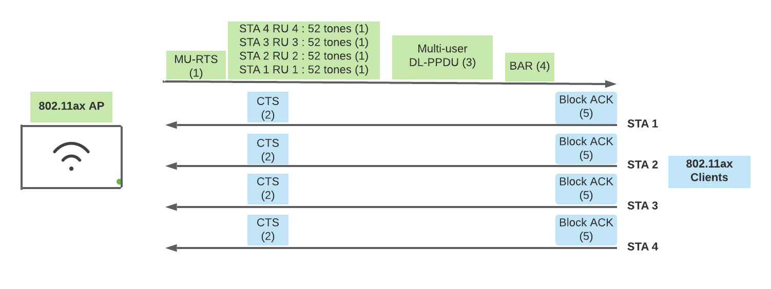
This section describes the DL-OFDMA process. Here, the AP has data ready to send to multiple associated 802.11ax clients and will transmit to each client STA in parallel.
-
The AP sends a multiuser request-to-send (MU-RTS) frame to associated client STAs.
-
The MU-RTS frame contains a list of RU assignments for each 802.11ax client and helps coordinate the multiuser frame exchange
-
The MU-RTS frame also contains a timer (network allocation vector (NAV)) to notify clients how long the exchange will take
-
This frame is transmitted using OFDM across the entire channel so legacy clients know to remain silent through the OFDMA frame exchange
-
-
The 802.11ax clients send clear-to-send (CTS) responses in parallel using their assigned RUs.
-
The AP transmits each client’s data in parallel using the assigned RUs.
-
The AP sends a block acknowledgement request (BAR) to confirm if each client received the transmission successfully.
-
If the data frames were received successfully, the clients respond with a block acknowledgement (ACK) in parallel.
Uplink OFDMA (UL-OFDMA)
This section breaks down the UL-OFDMA process. Here, the AP coordinates simultaneous transmissions from client STAs.
Note that early 802.11ax AP chipsets, such as the MR45/55, do not support UL-OFDMA. Instead, clients transmit their data to the AP sequentially using the OFDM process. More information about specific Meraki access point models is available on our website.
-
The 802.11ax AP sends a buffer status report poll (BSRP) to check how much buffered data the clients are ready to send.
-
Clients respond with a buffer status report (BSR). This helps the AP plan RU size and quantity.
-
The AP sends a multiuser request-to-send (MU-RTS) frame to all clients.
-
The MU-RTS frame contains a list of RU assignments for each 802.11ax client and helps coordinate the multiuser frame exchange
-
The MU-RTS frame also contains a timer to notify clients how long the exchange will take
-
This frame is transmitted using OFDM across the entire channel so legacy clients know to remain silent through the OFDMA frame exchange
-
-
The 802.11ax clients send clear-to-send (CTS) responses in parallel using their assigned RUs.
-
The AP sends one last trigger frame to coordinate each client’s transmission.
-
The clients transmit their data frames to the AP in parallel.
-
If the data frames were received successfully, the AP responds with a block acknowledgement (ACK).

Multiple Input, Multiple Output (MIMO)
MIMO technology, introduced in 802.11n, uses multiple antennas to take advantage of multipath, the way a signal takes different paths to reach the antenna. MIMO allows devices to identify the different paths the signals take to the receiver and sends unique streams of data, known as spatial streams, along different paths. Transmission across multiple spatial streams to a single client is known as single-user MIMO (SU-MIMO). Doubling the number of spatial streams effectively doubles the available throughput.

802.11ac expanded MIMO to allow the AP to use different spatial streams to transmit to multiple clients (up to four) simultaneously. This is known as downlink multiuser MIMO (DL-MU-MIMO).

MU-MIMO in 802.11ax allows up to eight clients across eight spatial streams and allows for clients to transmit to the AP simultaneously across different spatial streams (uplink, UL-MU-MIMO).

The number of spatial streams a device supports varies by manufacturer and model. Antenna capabilities are typically written in the form transmitters x receivers: spatial streams. For example, the MR55 5 GHz antenna capabilities are 8x8:8. This means it has 8 transmit antennas, 8 receive antennas, and 8 spatial streams.
Client devices do not have to be 802.11ax-capable to take advantage of APs with 8x8:8 antennas. Through techniques like maximal ratio combining (MRC), the AP can improve the strength of the signal it receives from its clients. Stronger signal strength means higher data rates and longer range for APs with 8x8:8 antennas over those with 4x4:4.
Both MU-OFDMA and MU-MIMO allow APs to communicate with multiple clients simultaneously. The difference is that MU-OFDMA uses different frequencies for each client and MU-MIMO reuses the same frequency in different spatial streams.
For more information on MIMO technologies, check out our article on Meraki MR SU-MIMO, MU-MIMO, and Beamforming.
Note that early 802.11ax APs, such as the MR45 and 55, do not support UL-MU-MIMO. They support DL-MU-MIMO with up to four clients per band. For more information about specific Meraki access point models, check out our website.
Basic Service Set (BSS) Coloring
Wi-Fi’s collision-avoidance mechanism, carrier-sense multiple access with collision avoidance (CSMA/CA), allows only one device to transmit on a given frequency at a time. Before transmitting, STAs check if there are any other transmissions on the channel. This check is known as a clear channel assessment (CCA). If any signal is heard, the STA backs off and tries again later.
Consider the following 2.4 GHz channel plan. To provide sufficient coverage for the site, four APs are required. However, there are only three channels available. In this case, channel 1 is reused on APs 1 and 4.
Note that BSS coloring is not specific to 2.4 GHz. 802.11ax also allows this feature for 5 GHz. 2.4 GHz is only used as an example.

While the APs are positioned to minimize overlap on the same channel (co-channel interference), some signals from AP 4 may still reach clients on AP 1, and vice versa. When this happens, clients in between APs 1 and 4 using channel 1 can hear traffic being transmitted in both coverage cells. Each time they need to transmit data, they must wait for both cells to be clear before transmitting.
A wireless network broadcast by a particular AP is known as a basic service set (BSS). To help mitigate the effects of co-channel interference, 802.11ax allows for a 6-bit BSS color field in the SIG-A field at the physical layer, as well as within management frames. This allows for up to 63 different BSS color values. If an STA hears traffic being transmitted, it checks the BSS color value. If the color value matches its own, the STA backs off to let the transmission complete. If the color value is different, it must be an overlapping cell; to avoid co-channel interference, the STA may disregard the ongoing transmission and transmit anyway.
Using BSS coloring in the previous example, AP 4 can use a different color value than AP 1. A client device physically located in between APs 1 and 4, associated to AP 1, disregards transmission it hears from AP 4 so it only needs to wait for AP 1’s BSS to be clear.

Target Wake Time (TWT)
TWT is a power-saving technology that allows an AP and client to negotiate when and how long a client can put its wireless radio into power-save mode. The goal is to minimize wireless medium contention and maximize the amount of time client wireless radios spend in power-save (PS) mode based on the client’s traffic needs. This allows the AP to manage wireless contention and potentially coordinate simultaneous transmissions with multiuser technologies as discussed in earlier sections of this document.
For more information on similar protocols, check out our document on Power-Saving Technologies.
Modulation and Coding Set (MCS) 10 and 11
MCSs define the possible data rates based on a variety of factors.
1024 QAM is used in MCS 10 and 11. To learn more about MCS values, check out the product overview and specifications.

For more information on modulation, refer to our 802.11 Fundamentals: Modulation document.
Wi-Fi 6 Backward Compatibility
When transmitting to or receiving from a client device, an AP must use only the protocols supported by the client. Client devices that are not capable of Wi-Fi 6 (legacy clients), such as clients only capable of 802.11a/b/g/n/ac, may still associate to a Wi-Fi 6 AP. However, they will not directly benefit from features specific to Wi-Fi 6. The client’s communication will be limited to the most recent Wi-Fi standard it supports. For example, an 802.11ac client may associate to a Wi-Fi 6 AP, but it will still only use features defined in the 802.11ac Wi-Fi standard.
When Wi-Fi 6-capable APs and clients are used in the presence of legacy clients, Wi-Fi 6 clients will still be able to use Wi-Fi 6 features like OFDMA and 1024 QAM.
When a Wi-Fi 6 client and a legacy client associate to the same Wi-Fi 6 AP, the Wi-Fi 6 client will still be able to use Wi-Fi 6 features like OFDMA and 1024 QAM.
While OFDMA is backward compatible with legacy devices, such as those only capable of 802.11n/ac, they will not directly benefit from OFDMA. When pre-802.11ax devices communicate with an 802.11ax AP, they still require the entire channel.