
BGP Routing for Cloud Management with IOS XE
BGP Fundamentals
Configuring BGP requires a solid understanding of networking principles, routing protocols and their inner workings. It may involve additional setup steps and troubleshooting tools beyond those outlined in this document. Proceed with caution to avoid network disruptions that could lead to a "resume generating event".
What is Border Gateway Protocol(BGP)?
Border Gateway Protocol (BGP) is a standardized exterior gateway protocol used to exchange routing information between autonomous systems (AS) on the internet or within large-scale networks. On Cisco Catalyst 9300 Series switches, BGP enables scalable and reliable routing in cloud environments, supporting dynamic route updates for efficient traffic management.

BGP Key Concepts
Before configuring and managing Border Gateway Protocol (BGP), understanding its core concepts is essential.
- Autonomous System (AS)
- An AS is a collection of IP networks under a single organization's control (e.g., an ISP or enterprise). BGP routes traffic between ASes. Each AS has a unique identifier called an ASN (Autonomous System Number).
- Internal BGP (iBGP) vs. External BGP (eBGP)
- iBGP: Operates within a single AS to share routing information among routers in the same network.
- eBGP: Runs between different ASes to exchange routing information across organizational boundaries.
- Path Attributes
- BGP uses attributes (e.g., AS Path, Next-Hop, Local Preference) to describe routes and influence routing decisions. These attributes help BGP select the best path to a destination.
- AS Path
- A list of ASes a route passes through to reach its destination. BGP uses this to prevent loops and choose shorter paths.
- Next-Hop
- The IP address of the next router a packet should go to reach its destination. In iBGP, the next-hop usually remains unchanged, while in eBGP, it’s typically the advertising router.
- Best Path Selection
- BGP evaluates multiple paths to a destination and selects the best one based on a series of criteria (e.g., shortest AS Path, highest Local Preference). This ensures efficient routing.
- Route Advertisement
- BGP routers advertise (share) routes with their neighbors (peers). Only the best path for each destination is advertised, reducing unnecessary traffic.
- Split-Horizon Rule (iBGP)
- In iBGP, a router does not advertise routes learned from one iBGP peer to another iBGP peer. This prevents routing loops within an AS.
- Route Reflection
- A technique in iBGP to reduce the need for a full mesh of connections. A route reflector redistributes routes to other iBGP peers, simplifying network design.
- Full Mesh Requirement (iBGP)
- In iBGP, every router typically needs to connect to every other router in the AS, creating a full mesh. This ensures all routers have consistent routing information but can increase complexity.
- Peering
- The process of establishing a BGP session between two routers (peers). Peers exchange routing updates and maintain a TCP connection (port 179) for reliability.
- Policy-Based Routing
- BGP allows administrators to enforce routing policies using attributes like Local Preference or AS Path manipulation. This controls how traffic enters or exits the network.
- Convergence
- The time it takes for all BGP routers to agree on the best paths after a network change (e.g., a link failure). BGP convergence can be slower than other protocols due to its scale.
- Dependence on IGPs (iBGP)
- iBGP relies on an Interior Gateway Protocol (e.g., OSPF, IS-IS) to resolve next-hop addresses and ensure reachability within the AS.
Differences Between BGP on Switches vs. Routers
BGP on Catalyst 9x00 Series switches is optimized for high-performance Layer 2/3 switching with limited routing table capacity compared to dedicated routers, which typically support larger-scale routing and more complex policies. Switches like the Catalyst 9300 leverage hardware acceleration for BGP, making them ideal for cloud environments requiring low-latency, high-throughput routing with simpler configurations.
|
Routes |
C9300X |
C9300 / MS390 |
C9300L / LM |
C9500H |
C9200CX |
|---|---|---|---|---|---|
|
IPv4 Total |
39,000 |
32,000 |
32,000 |
90,000 |
14,000 |
|
IPv4 Direct |
24,000 |
24,000 |
24,000 |
90,000 |
10,000 |
|
IPv4 Indirect |
15,000 |
8,000 |
8,000 |
90,000 |
4,000 |
|
IPv6 |
19,500 |
16,000 |
16,000 |
90,000 |
2,000 |
|
Multicast |
8,000 |
8,000 |
8,000 |
32,000 |
1,000 |
Reference: C9300 Datasheet
Reference: C9500 Datasheet
Reference: C9200 Datasheet
Supported Address Families and VRFs
The Catalyst 9300 Series supports multiple BGP address families, including IPv4 and IPv6 for unicast and multicast routing across multiple VRFs. Support for these will come in phases with the first phase supporting IPv4-unicast at launch
|
IOS-XE Release |
Feature Support |
|---|---|
|
17.18.x (Phase1 BGP) |
IPv4 Unicast, Default-VRF, Prefix-lists, AS-Path, Route-Reflectors |
|
Future (Phase2 BGP) |
IPv6 Unicast, L2VPN EVPN, Multicast, Multi-VRF, Route-Maps, Community Strings |
Prerequisites for BGP on Cloud
Hardware Requirements
The Cisco Catalyst 9300/9500 Series switches, along with the Meraki MS390 and C9200CX Compact switches supported running BGP in cloud environments. These switches require Cisco IOS-XE firmware version 17.18.x to enable BGP functionality, ensuring compatibility with advanced routing features and optimal performance.
|
Platform Family |
CloudSupported Models |
|---|---|
|
C9200 |
All C9200CX Cloud managed models only |
|
C9300 / X / L / LM |
All Cloud Managed Models |
|
MS390 |
All Models |
|
C9500 |
All UADP 3.0 Models (C9500-32C, C9500-32QC, C9500-48Y4C, C9500-24Y4C) |
Software Requirements
-
Cloud-Native IOS-XE 17.18.1+ is required configured on the network
Licensing Requirements
To enable BGP on Catalyst 9300 and 9500 Series switches, a standard Enterprise license is required, with the advanced license required for using Adaptive Policy.
|
License Level |
Features |
|---|---|
|
Enterprise |
BGP, OSPF, L3 Core |
|
Advanced Licensing (inclusive of Enterprise) |
Adaptive Policy, Application Visibility, Netflow |
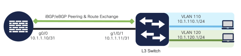
Network Topology and Design Considerations
BGP on Catalyst 9x00 Series switches supports both eBGP (External Border Gateway Protocol) for inter-autonomous system routing and internalBGP (Internal Border Gateway Protocol) for intra-autonomous system routing, with eBGP requiring connectivity between external peers and iBGP needing logical full meshing or techniques like route reflectors to reduce complexity. When designing cloud deployments, consider eBGP for connecting to external peers and iBGP for internal deployments.

iBGP vs eBGP
| Factors | iBGP (Internal Border Gateway Protocol) | eBGP (External Border Gateway Protocol) |
|---|---|---|
| Scope | Peering between routers in the same AS. | Peering between routers in different autonomous systems. |
| Route advertisement | Routes received from an iBGP peer cannot be advertised to another iBGP peer but can be advertised to an eBGP peer. | Routes received from an eBGP peer can be advertised to both eBGP/iBGP peers. |
| AS path addition | The local AS number is not added to the AS path attribute when advertising a route to an iBGP peer. | The local AS number is added to the AS path attribute when advertising a route to an eBGP peer. |
| Attributes | Local preference attribute is sent to an iBGP peer. | Local preference attribute is not sent to an eBGP peer. |
| AD | The default administrative distance is 200. | The default administrative distance is 20. |
| TTL | Default peers are set with TTL = 255. | Default peers are set with TTL = 1. |
| Topology | Requires full mesh topology. | Does not require full mesh topology. |
| Loop prevention mechanism | Uses BGP split horizon for loop prevention. | Uses AS path for loop prevention. |
What is iBGP?
Internal Border Gateway Protocol or iBGP is a BGP version used by routers in the same autonomous system (AS). Without using an IGP (Interior Gateway Protocol), iBGP enables routers to share routing data about external networks, such as the Internet. To avoid routing loops, iBGP peers must create a full mesh topology. iBGP bases its routing choices on network regulations and rulesets by using BGP features like local preference.
Characteristics of iBGP
-
iBGP operates within the same Autonomous System (AS).
- The next-hop addresses remain unchanged when routes are share
- It employs Split-Horizon Rules to prevent loops.
Advantages of iBGP
- Route-Reflection: Route reflection helps eliminate the need for a large number of iBGP peers
- Easy Configuration: iBGP is simpler to configure than eBGP, with Route-Reflectors and Peer-Groups simplifying configuration in bulk.
- Redundancy: In the case of failures, iBGP offers multiple routes for data path
Disadvantages of iBGP
- Full Mesh Requirement: iBGP requires a Full Mesh of iBGP peers. This results in numerous connections and can impact scale/performance
- Route Oscillation: Although iBGP is very effective, it is exposed to route oscillation, which in turn makes the network unstable.
- Slow Convergence: It takes relatively more time for the network to attain its stable state in case of a failure or a change.
What is eBGP?
An external Border Gateway(eBGP) allows communication between several autonomous systems (AS). Network connections via the Internet or between various organizations are made possible by eBGP. eBGP operates in the opposite manner of iBGP, i.e., inside the same AS. eBGP routes don’t need a full mesh topology and have an administrative distance of 20.
Characteristics of eBGP
- It can operate between different Autonomous Systems.
- Whenever a route is advertised, the next-hop address is updated.
- It employs AS Path Attribute to prevent loops.
Advantages of eBGP
- Inter-AS Connectivity: With eBGP, one can easily communicate between separate networks in different AS
- Flexibility in Route Advertisement: eBGP gives greater flexibility on which routes are advertised to neighboring AS.
- Improved Network Resilience: eBGP assists in improving network resilience by offering multiple paths for data transmission.
- Easy Troubleshooting: Easier to troubleshoot issues between each AS since each AS can be isolated and can be debugged independently.
Disadvantages of eBGP
- Higher Configuration Overhead: Although eBGP is easier than iBGP, it requires more configuration effort.
- Route Leaking: Poorly configured eBGP is prone to route leaking, which in turn causes network instability and security issues.
- Distance Vector Limitations: eBGP uses distance vector routing, which in most cases can result in the formation of routing loops if not well controlled.
- Higher Network Resource Requirements: eBGP is more network resource intensive so hardware and scale must be considered for large deployments.
Configuration Guide
Basic BGP Configuration
Configuration is done per-device. Which means each BGP router instance must be created on each switch/stack you plan to use it on.
General Steps to configuring BGP
- Create ASN
- Create a new router on Switch
- Configure redistribution and local networks to be shared with peers
- Configure any BGP filters needed
- Create Peer-Group
- Add Peer to that Peer-Group
- Repeat steps for other switches
ASN Creation
- From the BGP Routing page (Switching -> Configure -> BGP Routing) select “Add ASN” from the ASN tab.

- When creating a new ASN, ensure that the AS is unique.

- You can track usage of the ASN from the ASN Table.

- ASN instances can only be deleted if no BGP routers are associated to that AS
Configuring BGP Router and Router ID
-
Select “Add Router” from the main BGP Routing page.

-
Create a new BGP Router instance by selecting the ASN, capable switch and desired Router-ID. The Router-ID can be optionally configured to map to a loopback interface.
-
(Optional) Create the BGP Router instance and map the Router-ID to a Loopback interface. This interface can be pre-created from the Routing&DHCP interfaces page.

-
Once the BGP Router instance has been created, you should be able to “Enable” the Router from the BGP Router list. You may want to configure peers first and Enable the router later when fully configured.
Disabling a BGP Router is the same as doing a “no router bgp <ASN>” via CLI, it removes the entire BGP config from the device while leaving the config staged in the cloud.

Route Redistribution (connected, static, Local Networks)
-
Click the BGP Router to edit the instance.
-
Select Dynamic redistribution (All connected routes and/or Static Routes).

-
Select “Add Network” to enter custom subnets for redistribution. You can enable or disable each network individually.
-
Select “Save” to save your changes.

Peer-Group and Peer creation
Peer-Groups are used to manage peer/neighbor sessions. They are required even if there is a single peer connection. Peer-groups are helpful to manage many peers with common configurations and simplifies scale with support for 1:Many peer relationships.
Peer-Groups
-
To create a Peer-Group, select “Add Peer Group” from inside the BGP router instance.

-
Create your Peer-Group, this contains common configuration elements for peers.


-
Be aware that some settings are only available for iBGP or eBGP respectively.
-
iBGP Only Features
-
Route-reflector-client
-
-
eBGP Only Features
-
next-hop-unchanged
-
Disable-connected-check
-
ebgp-multihop
-
remove-private-as
-
Peers and Ranges
Within the Peer Group you can create multiple 'peer' or 'range' entries in each Peer Group. When configuring peers & ranges, be aware that ranges are passive constructs which cannot connect to other ranges.
Example: Use of "Range" on Core/Distribution level switches can simplify config across multiple IDFs/remote switches. Each remote switch would have a single peer configuration pointing to the Core switch, removing the need from building 2-way peer configurations on each core/IDF pair.
| Connectivity Compatibility | Peer | Range (Passive) |
|---|---|---|
| Peer | ✓ | ✓ |
| Range (Passive) | ✓ | X |
Peer: Neighbor IP of the remote iBGP/eBGP peer. Peers inherit peer group configurations by default but allow for overrides per peer.
Range: When you create a 'range', you specify a subnet range for the remote peers. Configuration is inherited from the peer-group and can be overriden with a peer config.
For example, a range of "192.168.0.0/24" would allow any remote peer in that subnet to connect to the local router.
Users can configure overlapping peers and ranges if desired. Peer config will take priority over range config
For example, user has a range of "192.168.0.0/24" and a single peer config of "192.168.0.100". The single peer config will take priority over the common peer config.
-
Create a Peer or Range.

-
To create a “Peer” select "Add Peer" button
-
Peers will inherit all the settings from the Peer-group by default.
-
(OPTIONAL) Peers can override certain configurations if needed. Any field that isn't overridden will preserve that config from the peer-group.

-
You can then override the following fields from the Peer Group.
Weight, default-originate, soft-reconfiguration, Prefix-list Inbound, AS-Path List Inbound, description, password, disable-connected-check, ebgp-multihop, update-source.
-
To create a “Range” click on "Add Range". This allows ANY router from a specific subnet to peer with the local bgp router.

-
The local BGP router would be configured for a Range. Remote BGP peers in that subnet range would have a single peer config pointing back to that local router.
-
(ex. Local BGP Router is the MDF switch, and all the remote IDF switches peer back to the MDF. In this example the MDF is configured with a listen-range and all the IDFs are configured with a single peer pointing to the MDF)
-
-
Range-to-Peers (1:Many) Example:

Peer-to-Peer Example:

BGP Route and Prefix Filtering
With BGP (Border Gateway Protocol) Implementations, filtering plays a crucial role in controlling route advertisements and acceptance to optimize network traffic, enhance security, and prevent routing loops. In dashboard, we support AS-Path access lists and Prefix-Lists for filtering. They're configured at a network-level and can re-used in different peer configurations. Route-map support will be added in the future.
AS-path access-lists utilize regular expressions to match and filter routes based on the sequence of Autonomous Systems (AS) in the path attribute.
Prefix-lists on the other hand, provide granular control over IP prefixes by specifying permit or deny actions with sequence numbers.

AS-Path Filters and Regex
- Access-lists can be created with multiple entries per list

- They're reference via "number" and can be applied to filter inbound or outbound exchanges
AS Regular Expression
This section explains the creation of a regular expression.
A regular expression is a pattern to match against an input string. When you build a regular expression, you specify a string that input must match. In the case of BGP, you specify a string that consists of path information that an input must match.
In the example in the section Path Filter , you specified the string^200$. You wanted path information that comes inside updates to match the string in order to decide.
A regular expression comprises:
Range
A range is a sequence of characters within left and right square brackets. An example is[abcd].
Atom
An atom is a single character. Here are some examples:
. The . matches any single character.
^ The ^ matches the start of the input string.
$ The $ matches the end of the input string.
\ The \ matches the character.
- The_matches a comma (,), left brace ({), right brace (}), the start of the input string, the end of the input string, or a space.
Piece
A piece is one of these symbols, which comes after an atom:
* The * matches 0 or more sequences of the atom.
+ The + matches 1 or more sequences of the atom.
? The ? matches the atom or the null string.
Branch
A branch is 0 or more concatenated pieces.
Here are some examples of regular expressions:
a* This expression indicates any occurrence of the letter "a", which includes none.
a+ This expression indicates that at least one occurrence of the letter "a" must be present.
ab?a This expression matches "aa" or "aba".
_100_ This expression means via AS100.
_100$ This expression indicates an origin of AS100.
^100 .* This expression indicates transmission from AS100.
^$ This expression indicates origination from this AS.
Prefix-List Filters
-
Multiple Permit/Deny Rules can be created in sequence and modified as needed.

-
(OPTIONAL) GE/LE Fields allow you filter prefixes by subnet size.
These fields allow you specify the desired subnet size filters for inclusion or exclusion.
- GE (Minimum Prefix Length)
- "Match only routes with a prefix length greater than or equal to this value. Must be more specific than the base prefix."
- example: GE = 30, will include prefixes larger or equal to /30 (so /30, /24, /16 etc)
- LE (Maximum Prefix Length)
- "Match only routes with a prefix length less than or equal to this value. Must be more specific than the base prefix."
- example: LE = 16, will include prefixes that are /16 or smaller (ex /18, /24, /32)
- Combining both GE and LE
- example: GE = 24, LE = 20, will include only prefixes between /20 and /24 (ex /24, /22) but would exclude /30 and /16 routes.
Use Case
-
CPE/Firewall peering (MX, SD-WAN, Viptella)
-
Simple eBGP/iBGP peering

-
Large Campus with Route reflectors

-
Traffic Engineering and High-Availability

Troubleshooting
Verification and Monitoring
Neighbor Status
The show ip bgp summary command displays the status of BGP neighbors, including their IP address, AS number, state (e.g., Established, Idle), and message statistics, which is critical for confirming that BGP peering is operational in cloud deployments. On a Catalyst 9300, this command helps verify whether eBGP or iBGP sessions are up and exchanging routes correctly.
Example Commands and Outputs:
- show ip bgp summary
Switch# show ip bgp summaryBGP router identifier 192.168.1.1, local AS number 65001BGP table version is 12, main routing table version 1210 network entries using 1440 bytes of memory10 path entries using 640 bytes of memory5/3 BGP path/bestpath attribute entries using 720 bytes of memory3 BGP AS-PATH entries using 72 bytes of memory0 BGP route-map cache entries using 0 bytes of memory0 BGP filter-list cache entries using 0 bytes of memoryBGP using 2872 total bytes of memoryBGP activity 10/0 prefixes, 10/0 paths, scan interval 60 secsNeighbor V AS MsgRcvd MsgSent TblVer InQ OutQ Up/Down State/PfxRcd10.1.1.2 4 65002 1234 1236 12 0 0 01:23:45 510.1.2.2 4 65001 1567 1569 12 0 0 02:15:30 3 - show ip bgp neighbor x.x.x.x [ advertised-routes | received-routes ]
Routing Tables
Example Commands and Outputs:
- show ip route
- show ip route bgp
Switch# show ip route bgpCodes: L - local, C - connected, S - static, R - RIP, M - mobile, B - BGPD - EIGRP, EX - EIGRP external, O - OSPF, IA - OSPF inter areaN1 - OSPF NSSA external type 1, N2 - OSPF NSSA external type 2E1 - OSPF external type 1, E2 - OSPF external type 2i - IS-IS, su - IS-IS summary, L1 - IS-IS level-1, L2 - IS-IS level-2ia - IS-IS inter area, * - candidate default, U - per-user static routeo - ODR, P - periodic downloaded static route, + - replicated routeGateway of last resort is not set172.16.0.0/24 is subnetted, 2 subnetsB 172.16.1.0 [20/0] via 10.1.1.2, 01:23:45B 172.16.2.0 [20/0] via 10.1.1.2, 01:23:45B 192.168.10.0/24 [20/0] via 10.1.1.2, 01:23:45
Event Log
-
Common Event Log messages exactly as they appear as headers
-
What does each message mean?
-
TBD
-