
Utilizing 1:1 NAT with Link Aggregation and Multiple Public IPs
Many networks require multiple public IP addresses for public facing resources. This article will outline configuring 1:1 NAT rules on the MX security appliance with Link aggregation and multiple public IP addresses.
Configuration
You may have public facing resources that users and customers need to access from the Internet. Port forwarding rules are used when the destination IP is the MX's Internet port IP address (either Internet port 1 or 2). If the ISP is providing a block of public IP addresses, a 1:1 NAT rule is configured to map the public IP address to the internal LAN IP address of the resource. These rules can be configured from Configure > Firewall > Forwarding rules.
In the following example a 1:1 NAT rule will be configured for two web servers. Each webserver will be using a different ISP (ie. a different Internet port on the MX):
Hostname:WebServer01
Service: web server (TCP port 80)
Public IP: 3.3.3.3
Hostname:WebServer02
Service: E-mail server and web mail (TCP ports 25, 80, and 443)
Public IP: 5.5.5.5

In the dashboard we would select Add a 1:1 NAT mapping and enter the following information:
Name: name for the mapping
Public IP: the IP address from the ISP that devices on the Internet will connect
LAN IP: local IP address of the device
Uplink: interface the MX should receive the inbound traffic from
Allowed inbound connections: firewall rules allowing inbound connections to the LAN device on the specified ports
The next figure shows the configuration required for our example:
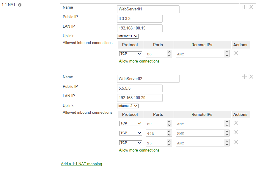
*Note: The only inbound connections that are allowed are the ports that are defined by Allow inbound connections.
Uplink Preferences
These mappings will allow the appropriate inbound connections to the LAN servers. Outbound traffic from these devices will follow the configured Primary uplink (Configure > Traffic shaping > Uplink configuration) unless Link aggregation has been enabled (in this case you could not be certain which interface the traffic would egress). An Uplink preference can be created to send traffic from a specific LAN host out a particular uplink.

In the above image we have created a preference to send all TCP/UDP traffic for WebServer02 out the Internet 2 uplink. This preference was created to avoid asymmetric routing. In our example, WebServer02, is also acting as a mail server. When it communicates with other mail servers they are expecting the IP address of our mail server to be the same as the 1:1 NAT statement we created. Without having the uplink preference this server would use the Internet port 1 uplink (and hence the Internet port 1 IP address).