
Cloud Managed EVPN Fabric Technical Guide
Large campus management trends continue to drive complexity for network operators. Cisco Cloud Managed Fabric provides a cloud-first approach to campus networking using standards-based BGP EVPN-VXLAN technology.
Cisco Advantage: Choice
Cisco offers three paths to fabric networking—Catalyst Center (SDA LISP), Meraki Dashboard (Cloud EVPN), and Programmable (on-prem)—giving customers flexibility based on their needs.
VXLAN Overview
VXLAN (Virtual Extensible LAN) is the foundation of modern fabric architectures, providing scalable network virtualization through MAC-in-UDP encapsulation.
VXLAN Encapsulation
VXLAN uses MAC-in-UDP encapsulation to tunnel Layer 2 frames over a Layer 3 network. The original Ethernet frame is encapsulated with additional headers:
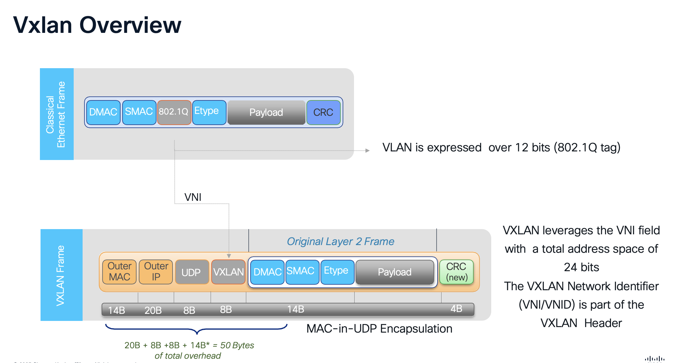
VLAN vs VNI Address Space
802.1Q VLAN ID: 12 bits = 4,096 VLANs
VXLAN VNI: 24 bits = ~16 Million segments
Key Points
-
50 Bytes Overhead: VXLAN encapsulation adds approximately 50 bytes to each frame (Outer Ethernet 14 + IP 20 + UDP 8 + VXLAN 8)
-
UDP Port 4789: VXLAN uses well-known UDP destination port 4789 (IANA assigned)
-
VTEP: VXLAN Tunnel Endpoints (VTEPs) perform encapsulation/decapsulation at the network edge
-
Layer 3 Transport: Outer IP header enables routing across any IP network (underlay)
-
Original Frame Preserved: The inner Ethernet frame is transported unchanged, preserving all Layer 2 information
VXLAN BGP EVPN Overlay
The combination of VXLAN and BGP EVPN creates a powerful, standards-based fabric solution:
VXLAN - Data Plane |
BGP EVPN - Control Plane |
| Standards-based encapsulation | Standards-based control plane |
| Uses UDP encapsulation | Uses Multiprotocol BGP (MP-BGP) |
| Transport independent | Supports various data planes: VXLAN (EVPN-Overlay), MPLS, PBB |
| Layer 3 transport (Underlay) | Many use-cases covered:
|
| Flexible namespace | |
| 24-bit field (VNID) provides ~16M unique identifiers | |
| Enables network segmentation |
Why BGP EVPN?
BGP EVPN provides efficient MAC/IP learning and distribution without flooding, enabling seamless workload mobility, optimal traffic forwarding, and simplified operations through a unified control plane for both Layer 2 and Layer 3 services.
Fundamentals of Fabric
- Underlay Network: The physical IP-based infrastructure that provides connectivity between fabric nodes, typically using routing protocols like OSPF for unicast forwarding. It handles the transport of encapsulated overlay traffic without awareness of the overlay services.
- Overlay Network: Built on top of the underlay using VXLAN encapsulation to extend Layer 2 and Layer 3 services. VXLAN Network Identifiers (VNIs) segment traffic into virtual networks, allowing for multi-tenancy and isolation.
- Control Plane: Leverages BGP EVPN (Ethernet VPN) for distributing MAC and IP reachability information. EVPN Route Types (e.g., Type 2 for MAC/IP advertisements, Type 3 for Inclusive Multicast Ethernet Tag, Type 5 IP Prefix route) enable efficient learning and reduce flooding.
- Data Plane: VXLAN tunneling encapsulates Ethernet frames in UDP/IP packets, with VTEPs (VXLAN Tunnel Endpoints) on fabric devices handling encapsulation/decapsulation. Supports symmetric IRB (Integrated Routing and Bridging) for L3 gateways.
Fabric Switch Roles
Fabric roles in an EVPN VXLAN fabric refer to the designated functions and positions that switches occupy within a spine-leaf architecture to enable efficient, scalable, and redundant overlay networking on top of an IP underlay.
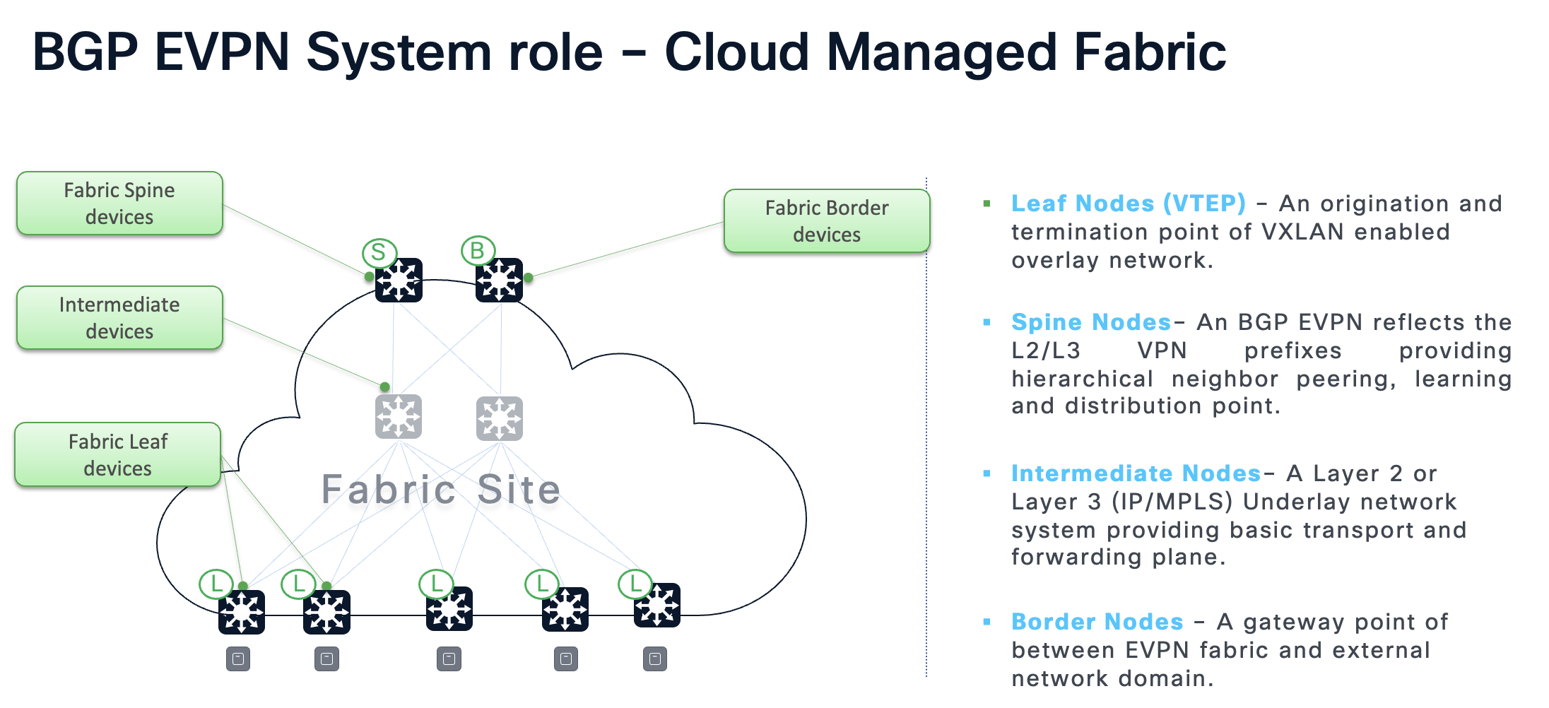
- Border: Serves as gateways between the EVPN VXLAN fabric and external networks, facilitating Layer 2 or Layer 3 connectivity to non-fabric domains. Handles route leaking, multicast handoff, and dynamic routing peering.
- Spine: Acts as the backbone of the fabric, interconnecting all leaf switches and providing redundant paths for traffic forwarding. Typically functions as BGP Route Reflectors to distribute EVPN routes efficiently.
- Leaf: Edge devices that connect directly to hosts or access devices, operating as VTEPs to encapsulate and decapsulate VXLAN traffic. Supports Layer 2 bridging within VNIs, Layer 3 routing via IRB, and features like ARP suppression and host mobility.
Multi-Role Configurations
Cisco Catalyst 9300 and 9500 series switches can operate in multi-role configurations, combining functions like spine, leaf, and border on a single device. Supported roles include: Spine, Leaf, Border, Border-Spine today. Support for Border-Spine-Leaf, and Border-Leaf will be supported in Phase 2.
Fabric Deployment Types
Distribution Level Fabric (Phase 1)
This model is ideal for brownfield environments or phased migrations where existing access layer infrastructure isn't replaced, and the fabric focuses on inter-building or site-wide connectivity.
Benefits of Distribution Level Fabric
- Easier Legacy Integration: Supports unmanaged or non-fabric-capable access switches connected via Layer 2 trunks, avoiding hardware upgrades at the edge
- Simplified Management: Fewer devices run the full EVPN overlay (VTEPs are at distribution), lowering configuration overhead and potential failure points
- Scalable External Connectivity: Distribution switches act as border nodes for efficient handoffs to WAN, data centers, or external networks
- Cost-Effective: Centralizes EVPN functions at distribution/core, supporting multi-site extensions without extending overlays to every access switch
Dependencies and Requirements
Hardware Requirements
Cloud Fabric Wired Supported Matrix
| Network Layer | Cisco Catalyst Switch Support | Minimum Software | Fabric Role |
|---|---|---|---|
| Access (CS) | Catalyst 9350, 9300/L/LM/X, 9200/L, 9200CX, MS390 | 17.18.2 | Layer 2 |
| Access (MS) | MS130X/R, MS150 | MS17+ | Layer 2 |
| Distribution | Cisco Catalyst 9300-X | 17.18.2 | Leaf |
| Core | Catalyst 9500-H, Catalyst 9300-X | 17.18.2 | Spine, Border-Spine |
| Network Edge | Catalyst 9500-H, Catalyst 9300-X | 17.18.2 | Border |
Cloud Fabric Wireless Supported Matrix
| Wireless Vendor | Wireless AP Support | Operational Mode | Forwarding Mode |
|---|---|---|---|
| Cisco | All MR and CW Access Points | Cloud | Distributed |
Recommendations
-
Spine Switches: Cisco Catalyst 9500-24Y4C/48Y4C/32C or Cisco Catalyst 9300X-12Y/24Y
-
Border Switches: Cisco Catalyst 9500-24Y4C/48Y4C/32C or Cisco Catalyst 9300X family
-
Leaf Switches: Cisco Catalyst 9300X family
-
Access Switches: Cisco or Meraki Layer2 switches that support SGT/Trustsec (c9350, c9300, c9200, MS390, MS150X/MS130X)
-
Wireless Access Points: Cisco CW91XX Access Points
Software Requirements
-
OS Version: IOS XE 17.18.2 or later
-
Licensing: Cloud Switching Advanced Licensing required for EVPN and Adaptive Policy
-
Management Tools: Cisco Meraki Dashboard (requires API key and internet access via TCP 443)
-
Authentication: Cisco Identity Services Engine (ISE) version 3.2+ or Cisco Meraki Access Manager
-
Underlay Protocols: OSPFv2 for unicast routing
-
Prerequisites: Layer 3 underlay network with point-to-point interfaces
Cloud Fabric Release Matrix
| Feature / Platform | 17.18.2 | Coming Soon |
|---|---|---|
| Release Timeline | ||
| General Availability | Dec 2025 | 1HCY26 |
| Platform Support | ||
| Access Layer | MS, 9200, 9300 | MS, 9200, 9300 |
| Distribution-Leaf | 9300-X | 9500-H, 9300-X |
| Core-Spine | 9500-H*, 9300-X | 9500-H*, 9300-X |
| Edge-Border | 9500-H*, 9300-X | 9500-H*, 9300-X |
| Features | ||
| Deployment Mode | Brownfield Access, Greenfield | Brownfield Access, Greenfield |
| Leaf System Mode | Cisco StackWise | EVPN Multihoming, Cisco StackWise |
| Network Support | Wired, Distributed Wireless | Wired, Distributed Wireless |
| Segmentation | Macro | Micro | Macro | Micro |
| Policy Engine | Cisco ISE, Access Manager | Cisco ISE, Access Manager |
* Recommended platform
Phase 1 Scale and Capacity
| Metric | IOS-XE 17.18.2 |
|---|---|
| Access Points | 1,000 |
| Fabric Clients | 10,000 |
| Distribution Blocks (Fabric Leafs) | 4 |
| Access Switches (in stacks) | 384 |
| Fabric Subnets | 300 |
| Sites | Single |
Fabric Reserved Interfaces and Addresses
For auto-underlay creation these interfaces are used during Fabric deployment. Make sure existing interfaces don't overlap and are unused prior to fabric deployment.
| Resource | Base | Range |
|---|---|---|
| Fabric ID | 1 | 1-8 |
| VRF-ID | 1 | 1-32 |
| Core VLAN | 965 | 965-997 |
| Underlay VLAN | 900 | 900-915 |
| L2 VNI | 10000 | 1-4094 |
| L3 VNI | 20000 | 1-32 |
| Fabric Loopbacks | Loopback100 | 100, 200-231, 300-331 |
| Underlay Subnets | 172.16.0.0/16 | /24 per subnet |
Network Segmentation
Macro Segmentation (VRF)
First level segmentation ensures zero communication between forwarding domains. Ability to consolidate multiple virtual networks into one physical network.
-
Virtual Routing & Forwarding (VRF) instances provide Layer 3 isolation
-
Scalable up to 20 VRF instances per Organization with IOS-XE 17.18.2
-
Create VRFs at scale via Fabric workflows in Dashboard
Micro Segmentation (SGT)
Second level segmentation ensures role-based access control between two groups within a Virtual Network. Provides the ability to segment the network into either line of businesses or functional blocks.
-
Secure Group Tags (SGT) / Adaptive Policy
-
Dynamic or Static SGT mappings support
-
Up to 60 SGTs per Organization
-
Integrate with Access Manager or Cisco ISE
-
Extend Policy within Fabric and/or beyond Fabric
Fabric Overlay Routing
This architecture supports three primary types of overlay subnets: Routed, DAG Routed, and DAG Bridged. Each type addresses different requirements for inter-subnet forwarding, scalability, and operational efficiency.
Routed Subnet
-
Layer 3 subnet located solely on a single leaf and cannot be stretched across multiple leaves
-
Requirements: Subnets must be unique and do not require matching VLAN IDs
-
Scale: Highly scalable
DAG Routed
-
Layer 3 subnet stretched across multiple leaves using a Distributed Anycast Gateway
-
BUM Traffic replication is restricted to access switch and does not bridge between switches attached to the same leaf
-
Requirements: Subnets require the same VLAN ID and share the same L3 subnet
-
Scale: Scalable across large networks
-
Recommended for scalable, secure fabric Wired and Wireless networks
Recommended for Client VLANs
DAG Routed mode provides flood-free IP subnet stretch with seamless mobility for wireless clients. Suggested for indoor/outdoor Wireless RF coverage between targeted Leaf switches.
DAG Bridged (DAG Routed + BUM Traffic)
-
Layer 3 subnet stretched across multiple leaves using a Distributed Anycast Gateway
-
Layer 2 BUM Traffic replication is distributed across all leaves
-
Requirements: Subnets require the same VLAN ID and share the same L3 subnet
-
Scale: Resource intensive and should be used only as required
-
Use for non-IP legacy endpoints, silent hosts, AP Management VLANs
DAG Bridged extends the flood domain and increases blast radius size. Implement selectively for VLANs that require Layer 2 flood between targeted Distribution layer Leaf switches.
Fabric Wireless
Distributed Wireless with Fabric
-
AP Management VLAN: Use DAG Bridged overlay
-
Client VLANs: Use DAG Routed overlay (Recommended)
-
Seamless Mobility across Multiple Leaf devices within the Fabric with Subnet stretch
Scalable Wireless Architecture
-
Seamless Mobility: Non-disruptive connection across network coverage
-
Flood-free core and access networks
-
DAG Routed provides flood-free IP subnet stretch for wireless clients
Underlay Design
MTU Considerations
-
VXLAN adds additional 50 bytes of overhead
-
Higher MTU recommended in Underlay
-
Change MTU to 9100 across the switches
Underlay with Routed Ports (Recommended)
-
Recommended for Greenfield deployments
-
Use routed ports workflow from Dashboard to create Routed ports between Leaf, Spine and Border
-
Enable OSPF on routed interface for Underlay Connectivity
-
Enable Custom Underlay from fabric workflow when provisioning
Underlay with SVI (Brownfield)
-
For deployments where Distribution to Core can't be transitioned to Routed ports
-
Underlay SVI and OSPF is automated as part of Fabric Workflows
-
VLANs 901-915 are used for Underlay routing
-
Allow 901-915 on the uplink trunk interfaces
-
Customizable Underlay IP pool (default: 172.16.0.0/16)
DHCP Relay for Overlay Subnets
-
DHCP Server in Global is supported
-
DHCP server must be reachable in Underlay
-
Single or Multiple DHCP Relay server support
-
Loopback100 is used to source DHCP Relay requests
interface Vlan101
  vrf forwarding Fabric
  ip dhcp relay source-interface Loopback100
  ip address 10.1.101.1 255.255.255.0
  ip helper-address global 10.0.42.1

interface Loopback100
  ip address 192.168.100.4 255.255.255.255
Automatic Underlay Provisioning
Auto-Underlay creation on a fabric automates the configuration of underlay connectivity between fabric nodes using reserved VLANs and IP pools.
Auto-Underlay VLAN Allocation
-
VLANs 900-915 are reserved for auto-underlay provisioning
-
Spine-to-Border links use EVEN VLAN IDs (900, 902)
-
Spine-to-Leaf links use ODD VLAN IDs (901, 903)
Underlay VLAN Mapping
| Underlay VLAN-ID | Non-Routed Subnet | Description |
|---|---|---|
| 900 | 172.16.0.0/24 | SPINE-A → BORDER |
| 901 | 172.16.1.0/24 | SPINE-A → LEAF |
| 902 | 172.16.2.0/24 | SPINE-B → BORDER |
| 903 | 172.16.3.0/24 | SPINE-B → LEAF |
Requirements for Auto-Underlay
-
RPVST+ must be enabled at the network level (requires pruning of VLANs to keep count < 300)
-
Port/VLAN configuration is still manual—configure links between switches using SmartPorts or Named-VLANs
-
Combined roles (Border/Spine) simplify underlay configuration
Border Connectivity
Border connectivity requires at least two connection types for proper fabric operation.
Management / Uplink Interface (Underlay)
-
Used for Dashboard connectivity
-
SVI (VLAN) based uplink is the default configuration
-
Routed Port based uplink requires a dedicated front-side port
-
A secondary Routed Port can be configured as backup
Fabric Egress (Overlay)
-
Required for traffic in/out of the fabric VRF
-
Each border requires at least one fabric egress port
-
SVI/VLAN or Routed Ports are supported for L3 interfaces
-
Once the interface is created, configure eBGP peering
Loopback Pool Connectivity
-
DHCP server must exist outside of the fabric, usually northbound of the border node
-
DHCP requests source from the switch's Loop100 interface on the underlay
-
The underlay subnet needs to be routable (reachable from DHCP server) via the Management/Uplink interface
Brownfield Migration
Cloud Fabric supports migrating existing brownfield networks into the fabric without disruption.
Effortless Underlay Migration (coming soon)
-
Take existing subnets and migrate them into the fabric at your own pace
-
Control subnet deployment and availability as part of the migration workflow
-
Post-migration pruning and optimization of the underlay
-
Multi-instance RPVST+ prevents loops during transition
-
Underlay migration automation prunes trunks automatically
Cisco Access Manager
Cloud-delivered access control services for simplified and rapid Zero-Trust adoption using identity-based micro-segmentation.
-
Flexible Authentication Options: For wired and wireless users, computers, and IoT
-
Secure RADIUS Transport: Over encrypted TLS tunnels (Cisco Managed) to the Meraki Dashboard
-
Multi-tenant SaaS: For High Availability and Scale globally
Supported Device Capabilities
| Model | 802.1X | MAB | VLAN | GPACL | TrustSec |
|---|---|---|---|---|---|
| Wireless (MR 30.7+) | |||||
| MR20, MR70 | ✅ | ✅ | ✅ | ✅ | - |
| 802.11ac Wave 2 / 802.11ax / Wi-Fi 7 | ✅ | ✅ | ✅ | ✅ | ✅ |
| Switching (MS17+) | |||||
| MS120, MS125, MS130 | ✅ | ✅ | ✅ | - | - |
| MS390, C9K-M (CS17.1+) | ✅ | ✅ | ✅ | ✅ | ✅ |
| C9200/CX, C9350, C9500H (IOS XE 17.18.1+) | ✅ | ✅ | ✅ | ✅ | ✅ |
Fabric Deployment Use-Cases / Phases
Scale and Capacity
| Fabric Phase | Access Points | Access Switches | Fabric Clients | VRFs | Distribution Blocks |
|---|---|---|---|---|---|
| IOS-XE 17.18.2 | 300* | 500* | 3000* | 20 | 16 (phase 1.5) |
* Scale numbers subject to change pending scale testing and validation.
Phase 1 (IOS-XE 17.18.2): Distribution Level Fabric
This architecture focuses on deploying the EVPN fabric at the distribution layer, where Catalyst 9500/9300x switches act as leaf nodes connected to traditional Layer 2 access switches. It enables overlay services for segmentation and mobility while maintaining existing access layer designs.
-
Ideal for initial migrations
-
Quick wins in scalability for multi-tenant environments
-
Office buildings or campuses
-
Fabric originates at the Distribution Layer
-
No interruption to Access Layer devices during Fabric transition
Phase 1.5 (Coming soon in 1HCY26): EVPN Multihoming & Extended Features
Building on Phase 1, this release adds EVPN Multihoming support at the distribution layer with 9300X/9500H switches, providing dual control plane and distributed forwarding capabilities.
-
EVPN Multihoming with 9300X or 9500H at Distribution Layer
-
Active/Active load-balancing
-
Enhanced redundancy at Distribution Layer
-
9500H support as Leaf role
Fabric Creation Workflow
Deploy and operate your network fabric in the following simple steps:
Step 1: Create a Fabric Topology
-
Navigate to Organization → Fabric and create a new fabric
-
Name the fabric and select the networks to include
-
Network selection determines which switches appear in the role assignment table
-
Assign device roles (single or multi-role configuration)
Step 2: Configure Underlay
-
Underlay Loopback IP Pool: Used for loopback creation, must be routable from the underlay
-
Underlay Core IP Pool: Used for auto-underlay VLANs 900-915, only needs local significance
-
Custom Underlay: If enabled, disables auto-underlay allowing use of existing underlay or Routed Ports
Step 3: Create VRFs and Subnets
-
First fabric automatically creates a "Fabric" VRF
-
Multiple VRFs supported per fabric (up to 20)
-
Each fabric requires unique VRFs—cannot reuse existing underlay VRF
-
Create Fabric Subnets: None = Routed, Anycast Gateway = DAG Routed, Anycast Gateway + Broadcast = DAG Bridged
-
Select which leaves the subnet is available on (Routed only on single leaf, DAG types can span multiple)
-
External DHCP server required for proxying DHCP requests from fabric clients
-
VLAN-ID must be unique and cannot use existing SVI/VLAN-ID
Step 4: Configure Border Routing
-
Create L3 interface for each border (SVI/VLAN or Routed Ports supported)
-
Configure eBGP peer once the interface is created
-
Create border egress interfaces for traffic in/out of the fabric VRF
Step 5: Preview, Stage, and Deploy
-
Review proposed configuration changes
-
Go back and modify if needed, or save to staging
-
Plan a change window for deployment
-
Deploy configurations to fabric nodes
-
Operate your network and migrate underlay subnets as needed
Troubleshooting
Fabric Assurance
-
Single Dashboard view for all Fabric Assurance
-
Fabric role summary (single and multi-role devices)
-
VRF summary
-
BGP neighbor status across all Fabric Devices and External Handoff devices
-
VXLAN tunnel status across all Fabric devices
Troubleshooting Checklist
| ✓ | Check Item | Details |
|---|---|---|
| ☐ | Device Firmware | Verify IOS-XE 17.18.2 or later |
| ☐ | Network Level Settings | RPVST+ enabled, VLANs pruned (< 300) |
| ☐ | Underlay Connectivity | Verify OSPF adjacencies and loopback reachability |
| ☐ | BGP EVPN | Check BGP neighbor state and EVPN route exchange |
| ☐ | VXLAN Tunnels | Verify NVE interface and VTEP peers |
| ☐ | Fabric Subnets | DAG pingable? VNI mapping correct? |
| ☐ | Client Connectivity | Client-to-Client ping, DHCP working? |
| ☐ | Dashboard Sync | Switch Config Updater synced? |
Common CLI Commands
# Verify BGP EVPN neighbors
show bgp l2vpn evpn summary

# Check VXLAN NVE peers
show nve peers

# Verify VNI mapping
show nve vni

# Check EVPN routes for a specific MAC
show bgp l2vpn evpn route-type 2

# Verify anycast gateway
show l2vpn evpn default-gateway

# Check EVPN EVI details
show l2vpn evpn evi detail

# Verify loopback interfaces
show ip interface brief | include Loopback
RPVST+ Requirement
RPVST+ must be enabled at the network level for auto-underlay. This requires pruning of VLANs to keep VLAN count below 300.