
Meraki and Cisco Collaboration Teleworker Solution for Businesses
Introduction
In today’s digital transformation age businesses are looking for collaboration, networking, security and connectivity services that meet their needs. They are often challenged with a variety of complex solutions and providers to choose from.
The purpose of this solution guide is to provide best practices on how businesses can leverage Cisco Meraki’s cloud networking architecture and how Cisco Meraki networks should be configured and deployed taking full advantage of the benefits offered by Cisco’s on-premises and Cloud Collaboration platforms. This recommended network configuration is based on a Cisco tested and validated architecture optimized for the various Collaboration platforms such as Webex Meetings, Unified Communication Manager, Webex Calling, and Cisco BroadWorks. The solution utilizes the Webex Meetings client, the Webex Teams client, and/or a Cisco phone and it focuses on teleworker deployments.
Recommendations provided in this document can serve as the basis to create a comprehensive solution that allows for rapid and seamless Teleworker deployment, ease of management and troubleshooting, AutoVPN technology, and optionally service continuity with 4G LTE failover. The solution enhances the user experience for end-customers and providers by bringing together the best of breed in cloud-managed networking and collaboration.
The guide walks through some of the technical aspects of the solution and goes over the process of creating a network blueprint optimized for Cisco Collaboration platforms that can be used for new service creation allowing for consistency and standardization across Teleworker locations. Guidance on how to operationalize the use of the blueprint network at scale is also provided in this document.
Key Benefits
There are several benefits that businesses can gain from leveraging Cisco Meraki’s cloud networking architecture in conjunction with Cisco’s Collaboration platforms for branch deployments. Below is a list of the key benefits of this solution.
-
Mitigate over-the-top (OTT) related challenges
-
Eliminate manual phone provisioning processes
-
Based on Cisco’s blueprint network optimized for Cisco Collaboration platforms
-
Rapid and consistent Teleworker deployment
-
Intuitive and centralized cloud-based management
-
Additional visibility of endpoints, networks and traffic usage for troubleshooting
-
Network intelligence and analytics
-
WAN monitoring and alerting for proactive response
-
Failover capabilities for service continuity
Prerequisites
In order to deploy this solution, the following is required. Readers of this document should have...
-
Prior experience working the Cisco Meraki dashboard and Cisco Collaboration platforms in addition to being familiar with the concepts and terminology of local area networking, VPN and VoIP.
-
Readers should have access to the Cisco Meraki dashboard. Instructions on how to create a dashboard account and organization can be found in the Creating a Dashboard Account and Organization article.
-
Access to the management portal for the Cisco Collaboration platform being used. Cisco Webex, Cisco Unified Communications Manager, Webex Calling or Cisco BroadWorks.
-
Cisco Meraki devices along with their respective license keys. Refer to Table 1 of the Appendix for the specific device models, technical specifications and sizing guide.
Hardware Used and Options
There are many different designs and architectures that can be utilized in these teleworker solutions. Below is a list of hardware
-
Security Gateway
-
Meraki MX 64/65W models (teleworker)
-
Meraki MX 67/68W models (teleworker)
-
Meraki Z1/Z3/Z4(c) models (teleworker)
-
Meraki MX 84, 100, 250, 450 (VPN Hub)
-
-
Wireless Access Points
-
Meraki MR access points (teleworker)
-
-
When we are referring to the configuration as Teleworker Gateway or SD-WAN & Security in the side menu in dashboard, these two can be used interchangeably.
-
When using a template “Security & SD-WAN” is what will be in the menu. These templates can be applied to Meraki WAN Appliances and Meraki Teleworker gateways with the same template.
-
When using the “Blueprint Network” or configuring networks on network by network basis, the Meraki WAN Appliance will show “Security & SD-WAN”. The Meraki Teleworker Gateway will show “Teleworker Gateway”
Overview of Deployment Architecture
This section provides an overview on how the solution is to be deployed by businesses. It assumes that you already have a Meraki AutoVPN network configured and operational and provides details on the network infrastructure to be installed at Teleworker premises as well as general guidelines on the provisioning process.
Teleworker Infrastructure
The network equipment to be installed at the Teleworker premises will consist of a Meraki Z3 Teleworker gateway and a Cisco Desk phone or a Cisco Headset to enable the remote worker to communicate effectively.
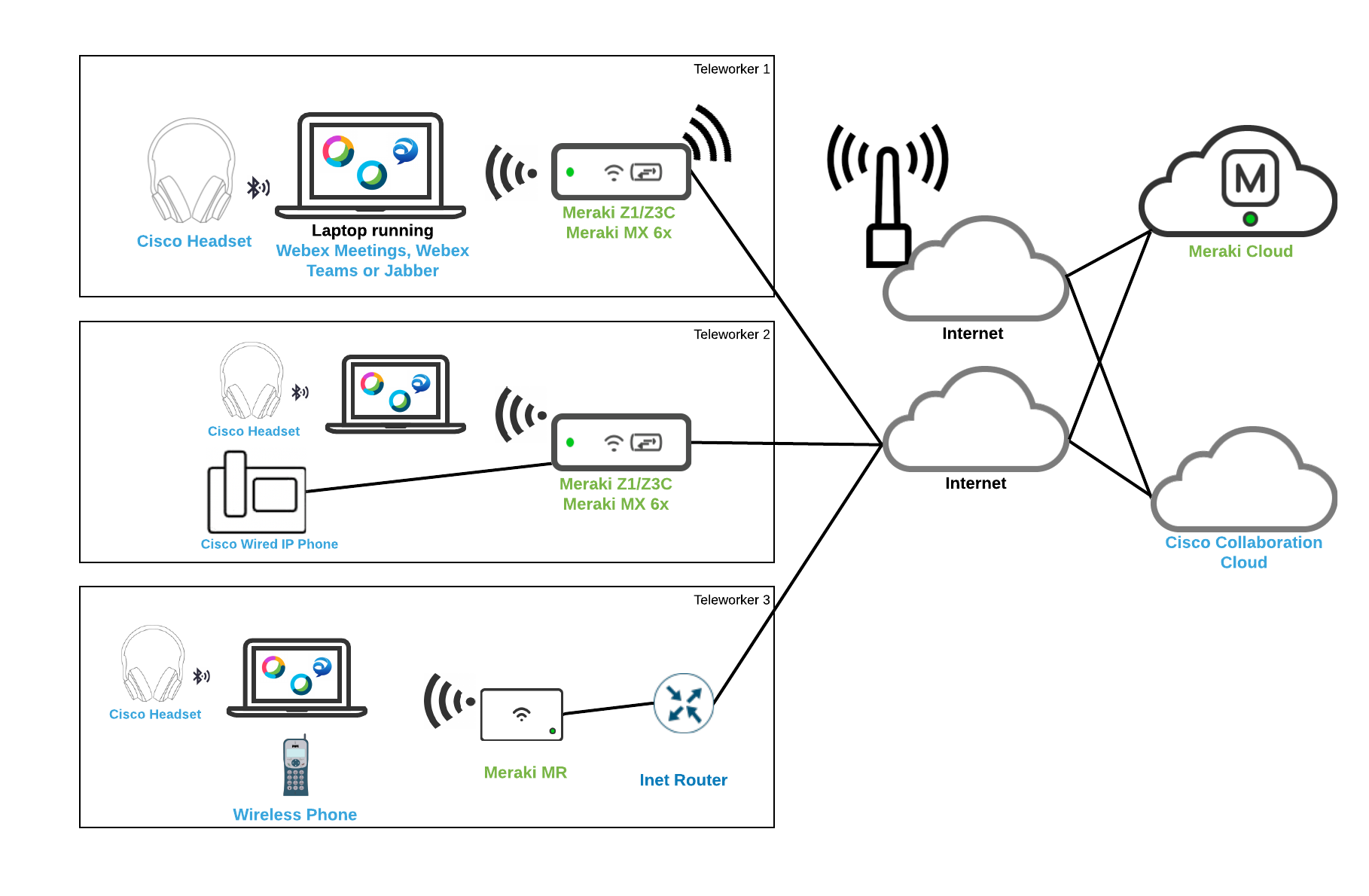
Specific device model information, technical specifications and a sizing guide is available in Table 1 of the Appendix.
Setup and General Provisioning Options
There are two options to consider when deploying this solution.
-
Creating a network template that is applied to all teleworker networks that are alike. This provides 100% consistency in deployment. Since this method is using a template, most configurations will be performed in the template and then are distributed to the individual networks upon saving of the template changes. This provides the greatest degree of consistency and single point of management. The trade-off for a template network deployment is that many local network configuration changes cannot be performed for one off use cases. Choose this option if you prefer less management overhead at the cost of individual Teleworker site customization.
-
Creating a Blueprint Network that is then cloned for the creation of all other networks. This provides consistent network creation for deployment. Since this method is not using a template, following initial deployment, configuration changes to all teleworker networks will need to be made on an individual network by network basis. Configuration change overhead can be greatly reduced by using the API to configure all site changes simultaneously. Choose this option if you prefer a high degree of Teleworker site customization at the cost of more management overhead.
Setup and General Provisioning - Template Network Option
In order to deploy this solution using the best practices provided in this document, the following workflows must be performed in order by the administrator. The initial setup consists of...
-
Configuring the general settings for the organization
-
Creating the Template Network
The next sections walk through the process of configuring the base organization as well as the template network.
Creating and Applying Configuration Templates
This section walks through the process of creating the template network that will serve as the base configuration for the network infrastructure. This will be used as a starting point for new customer deployments as well as the ongoing configuration point for all of the teleworker configurations. The template network represents the Cisco recommended settings for successful deployments.
New Template Creation
After a dashboard account and organization have been created:
Step 1. Log in to the Cisco Meraki dashboard as an organization administrator
Step 2. Select Configuration templates from the Organization tab
Step 3. Select a Create a new template and select Create new then make you provide a name that clearly describes its purpose (e.g. “Template-Teleworker-VPN”) and click the Add button. Click Close and then Save changes
Note: There is currently a limitation in the Meraki dashboard where you are not able to change the Regulatory Domain for the Wireless settings on the Teleworker gateway if you create the network as a Combined network – ensure that you select the Security appliance setting to avoid this limitation.
Step 4. Select the newly created template (e.g. “Template-Teleworker-VPN”) from the Network dropdown tab. We will make all our configuration changes in this template and apply the template to all future created networks.
Network-wide (General) Configuration
For the purposes of consistency, it is recommended to configure the general settings that are common across Teleworker locations in the blueprint network. Below is a list of the most relevant settings available when selecting General under the Network-wide tab.
-
Country/Region sets the country of network. Regulatory domain is set based on this
-
Local time zone sets the time zone of the network
-
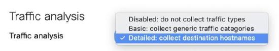
Traffic analysis specifies the level of detail desired for traffic analysis
For added visibility, use the Detailed option for Traffic analysis. This enables collection of detailed information about the destinations which can be useful for troubleshooting.

Additionally, the Traffic analysis section allows for the definition of specific destinations to track and to build a custom pie chart. The destinations can be defined based on a HTTP hostname, Port, IP range or IP range & port.
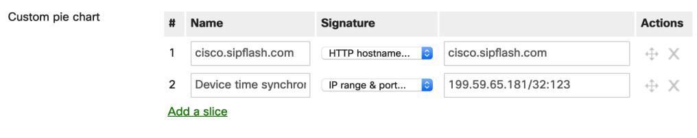
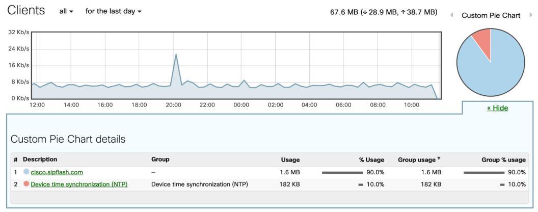
When a custom pie is configured and there is matching traffic to the destinations, traffic usage information will be available when selecting Clients from the Network-wide tab.
The following section goes through the Teleworker gateway specific configuration.
Template Teleworker Appliance Configuration (Z1/Z3/Z4 or MX 6x)
The configuration steps described in this section are specific to the Meraki Z-Series Teleworker gateway. The Z-Series line has built-in wireless and VPN capabilities and is used in all the Teleworker deployments as outlined in Table 1 of the Appendix. Use the following steps to configure this portion of the reference network:
Step 1. Navigate to the Security & SD-WAN tab and select Addressing & VLANs
Step 2. From the Deployment Settings section of the page ensure that the Routed and MAC address options are selected for the Mode and Client tracking settings respectively
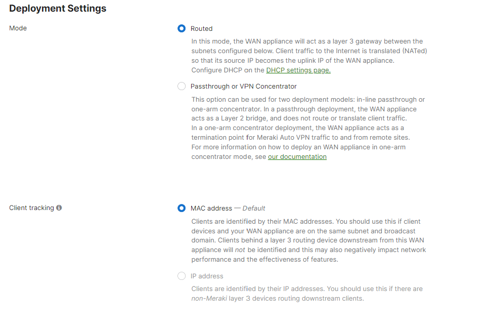
Note: The Routed mode allows the Teleworker gateway to act as a layer 3 gateway for the different subnets created and all Internet bound client traffic will be translated (NAT). More information on this is available in the MX Addressing and VLANs article.
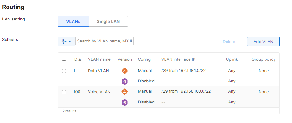
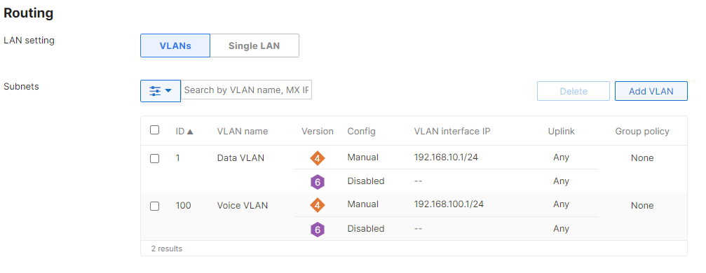
Step 3. Scroll down to the Routing section and enable the use of VLANs
Note: Teleworker gateways define the VLANs and subnets that exist in the remote network. It is best practice to ensure traffic is segregated by creating dedicated VLANs for voice and data traffic.
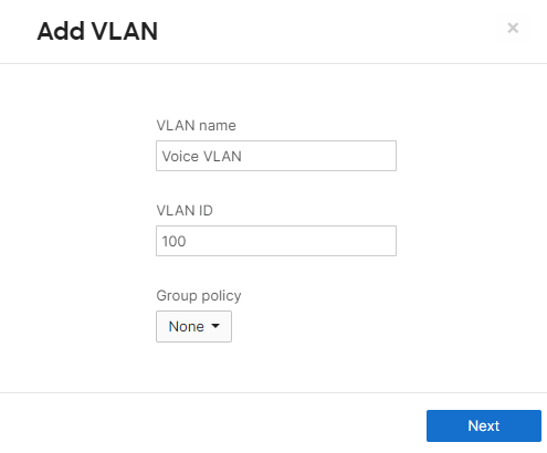
Step 4. Click on the Add VLAN button to create each of the VLANs needed for remote networks.
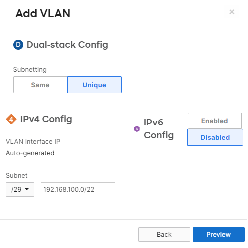
For the Subnet here, we are able have dashboard automatically create non-overlapping subnets out of a larger supernet. This avoids the need to have to configure each networks IP addressing as the networks are created.
-
Name: Use a name that describes the purpose of the VLAN (e.g. “Voice VLAN”)
-
Subnet: Defines the subnet to be mapped to the VLAN. Use Classless Inter-Domain Routing (CIDR) notation. We can configure Unique here as in the example above. Each new network that the template is added to will provision a unique /29 subnet out of the larger 192.168.100.0/22 network
-
VLAN ID: The assignment of the VLAN tag. Use a number between 1 and 4096
-
Group Policy: Specifies the group policy to be applied to traffic within the subnet
Step 5. Click Preview then Update after entering the VLAN information and confirm VLAN creation. Repeat the process for each of the VLANs needed. Note that the VLAN Interface IP column will be “Auto-generated” and the Appliance will take the first IP each time a subnet is provisioned.
Step 6. Navigate to the Security & SD-WAN tab and select DHCP. Each of the created subnets will have its own DHCP server configuration, ensure the Run a DHCP server drop-down option is selected for all VLANs.
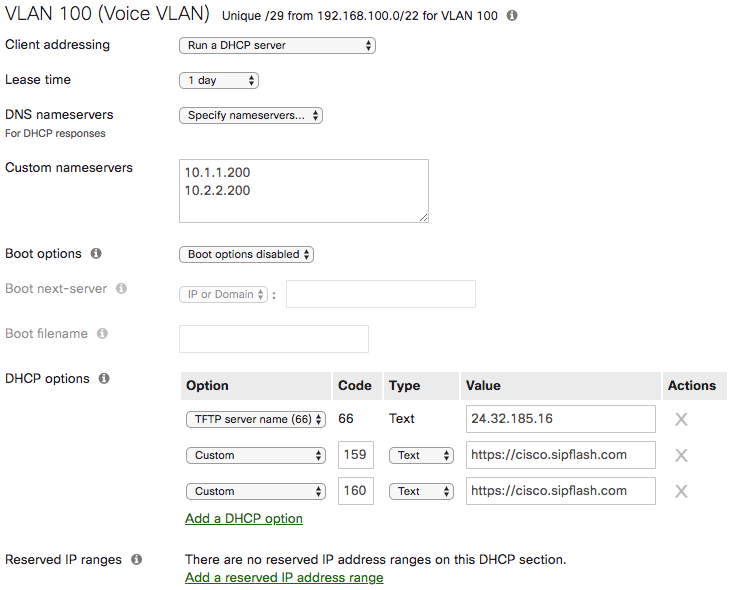
Step 7. Scroll down to the DHCP server configuration for the Voice VLAN. In order to allow IP phones to retrieve configuration and a hosted phone firmware, add custom DHCP options entries with the following configuration:
-
DNS namesservers: Enter the DNS servers for your organization for internal name resolution
-
Option: Select Custom from the drop-down to configure an unlisted DHCP option
-
Code: Enter the number for the DHCP option (e.g. 150 for TFTP server address)
-
Type: Select Text
-
Value: Enter the URL or IP address information
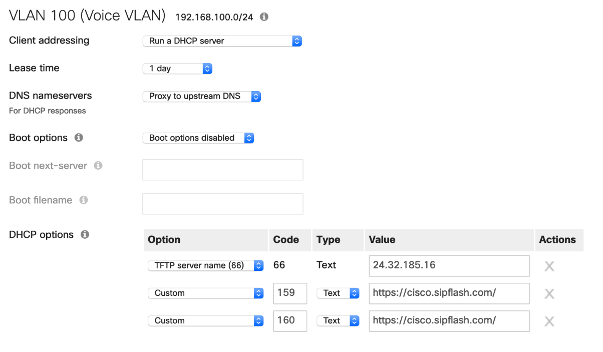
Note: It is recommended to use at least two of the custom DHCP options to eliminate the need for manual phone provisioning. The sequence Cisco IP phones (MPP) use when booting up is: 66, 160, 159, 150. Enterprise (Non-MPP) phones use DHCP option 150 and 66.
Step 8. Provide the appropriate configuration settings for the Data VLAN, and any other VLAN that DHCP will be configured for.:
-
DNS namesservers: Enter the DNS servers for your organization for internal name resolution
-
Option: Select Custom from the drop-down to configure an unlisted DHCP option
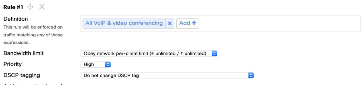
Step 9. Navigate to the Security & SD-WAN Scroll down to SD-WAN & traffic shaping and configure a new rule for All VoIP & video conferencing traffic. Refer to the image below for additional details on how to configure the rule.
Template Wireless Configuration (Z1/Z3/Z4 or MX6X)
This section covers the wireless configuration piece of the reference network. It is highly recommended to perform a pre-install RF survey as outlined in the Wireless VoIP QoS Best Practices document. Follow the next steps to configure the wireless settings of the blueprint network.
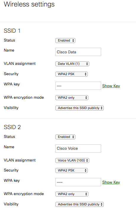
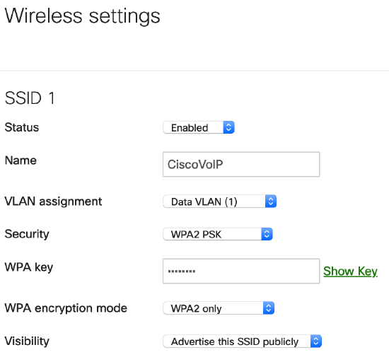
Step 1. Configure a dedicated SSID for voice by navigating to the Security & SD-WAN tab and selecting Wireless settings
Step 2. Change the Status of SSID 1 to Enabled. Rename the default SSID. Use a name that describes its purpose (e.g. “CiscoVoIP”)
Step 3. Change VLAN assignment to the Voice VLAN that you created above.
Step 4. Change the SSID Security to WPA2 PSK. Enter a WPA Key for clients to connect to the SSID, and change WPA encryption mode to WPA2 only. If 802.1x is desired for wireless, select WPA2 Enterprise then under Authentication select My RADIUS server and input the organizations RADIUS servers IP addresses.
This concludes the Meraki Teleworker gateway wireless portion of the configuration for the network template.
New Network Creation (Z1/Z3/Z4 or MX6X)
After the Template-Teleworker-VPN template is created we can now create new networks and apply the template we just created:
Step 1. Log in to the Cisco Meraki dashboard as an organization administrator
Step 2. Select Create a new network from the Network dropdown tab
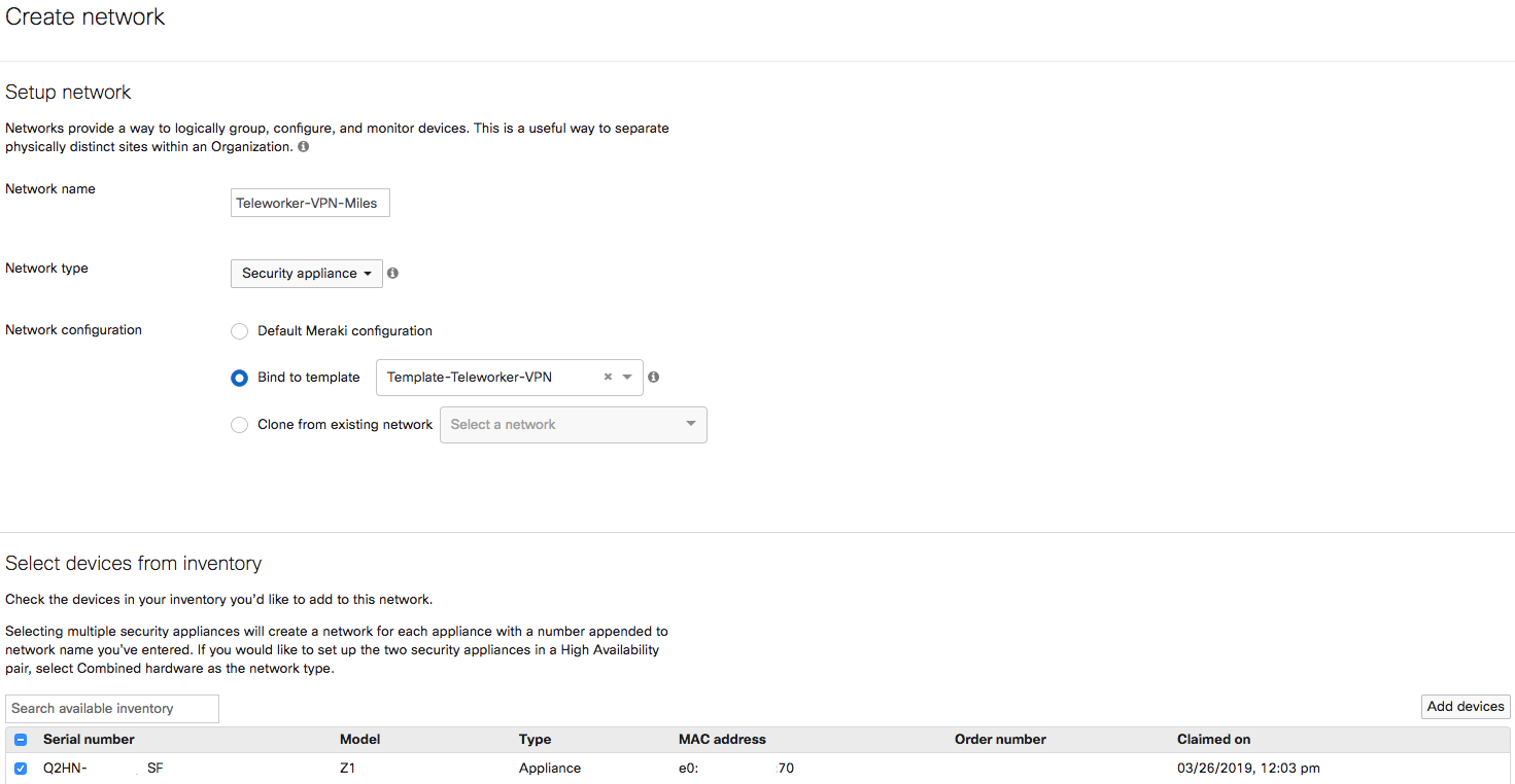
Step 3. Enter a Network name and make sure it clearly describes its purpose (e.g. “Teleworker-VPN-Miles”) and click the Add button
Step 4. Set the Network type to Security appliance, change Network configuration set to Bind to template and select the Template-Teleworker-VPN from the list. Meraki configuration, then scroll down and click Create network.
Step 5. Select a “Teleworker Gateway or WAN Appliance” from the bottom to add to this network. Then scroll down and click Create network.
Template Wireless Configuration (Wireless Only)
This section covers the wireless configuration piece of the reference network. Depending on the user equipment being deployed, it may be desired to create two VLAN’s, one dedicated to Data (laptop, mobile devices etc) and a second dedicated to wireless phonesIt is highly recommended to perform a pre-install RF survey as outlined in the Wireless VoIP QoS Best Practices document.
Step 1. Configure a dedicated SSID for voice by navigating to the Wireless tab and selecting SSIDs
Step 2. Change the Status of SSID 1 to Enabled. Rename the SSID. Use a name that describes its purpose (e.g. “CiscoTeleworker” or “CiscoVoIP” etc)
Step 3. Change the SSID Security to WPA2 PSK. Enter a WPA Key for clients to connect to the SSID, and change WPA encryption mode to WPA2 only. If 802.1x is desired for wireless, select WPA2 Enterprise then under Authentication select My RADIUS server and input the organizations RADIUS servers IP addresses.
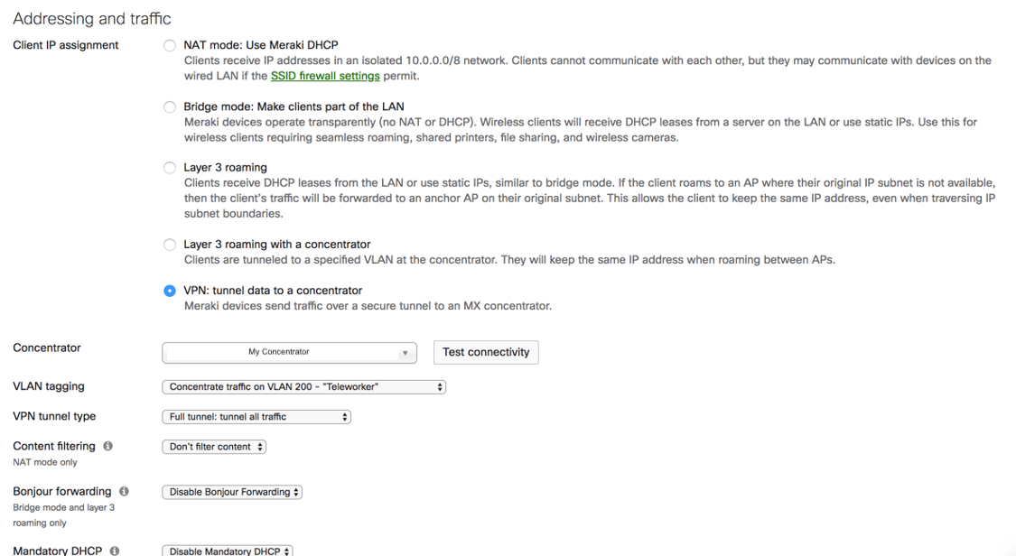
Step 4. Change Addressing and traffic to the VPN: tunnel data to a concentrator. Select the Concentrator you want to tunnel the data to ( you will need to have a Meraki VPN Concentrator in your organization to select). Select Full tunnel: tunnel all traffic. Once the template is applied to the network you can “Test connectivity”
Step 5. Configure security for your SSID(s) by navigating to the Wireless tab and selecting Firewall & traffic shaping. Select the SSID to have changes applied. You can set firewall rules (L3/4/7 based rules) By Default voice is prioritized.
Step 6. Ensure that the Concentrator has the required DHCP configurations in place for phones to get their needed configurations.
New Network Creation (Wireless only)
After the Template-Teleworker-VPN template is created we can now create new networks and apply the template we just created:
Step 1. Log in to the Cisco Meraki dashboard as an organization administrator
Step 2. Select Create a new network from the Network dropdown tab
Step 3. Enter a Network name and make sure it clearly describes its purpose (e.g. “Teleworker-VPN-Wireless-Miles”) and click the Add button
Step 4. Set the Network type to Wireless, change Network configuration set to Bind to template and select the Template-Teleworker-VPN from the list. Meraki configuration, then scroll down and click Create network.
Step 5. Select an Access Point from the bottom to add to this network. Then scroll down and click Create network.
This concludes the steps for the WAN Appliance, Teleworker Gateway, and Wireless portion of the configuration for the network template.
Setup and General Provisioning - Blueprint Network Option
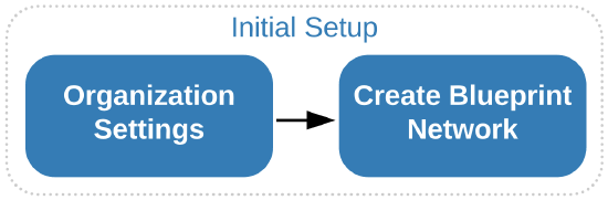
In order to deploy this solution using the best practices provided here for Blueprint Network Method, the following workflows must be performed in order by the administrator. The initial setup consists of...
-
Configuring the general settings for the organization
-
Creating the blueprint network
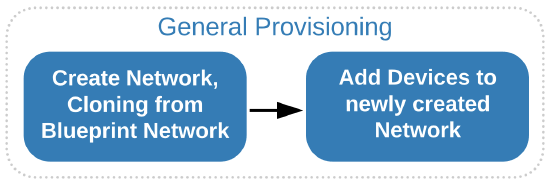
After initial setup, when the base organization containing the blueprint network is available, administrators can follow the below workflow for deploying new Teleworker sites.
-
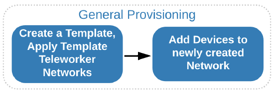
Create a new network by cloning the blueprint network
-
Add devices to the newly created network
The next section will walk through the process of configuring the base organization as well as the blueprint network.
Creating the Blueprint Network
This section walks through the process of creating the blueprint network that will serve as the base configuration for the network infrastructure and will be used as a starting point for new customer deployments. The blueprint network represents the Cisco recommended settings for successful deployments.
Network Creation
After a dashboard account and organization have been created:
Step 1. Log in to the Cisco Meraki dashboard as an organization administrator
Step 2. Select Create a new network from the Network dropdown
Step 3. Enter a Network name and make sure it clearly describes its purpose (e.g. “Blueprint Teleworker Network”) and click the Add button
Step 4. Leave Network type set to Security appliance, leave Network configuration set to Default Meraki configuration, then scroll down and click Create network.
Note: There is currently a limitation in the Meraki dashboard where you are not able to change the Regulatory Domain for the Wireless settings on the Teleworker gateway if you create the network as a Combined network – ensure that you select the Security appliance setting to avoid this limitation.
Network-wide (General) Configuration
For the purposes of consistency, it is recommended to configure the general settings that are common across Teleworker locations in the blueprint network. Below is a list of the most relevant settings available when selecting General under the Network-wide tab.
-
Country/Region sets the country of network. Regulatory domain is set based on this
-
Local time zone sets the time zone of the network
-
Traffic analysis specifies the level of detail desired for traffic analysis
For added visibility, use the Detailed option for Traffic analysis. This enables collection of detailed information about the destinations which can be useful for troubleshooting.
Additionally, the Traffic analysis section allows for the definition of specific destinations to track and to build a custom pie chart. The destinations can be defined based on a HTTP hostname, Port, IP range or IP range & port.

When a custom pie is configured and there is matching traffic to the destinations, traffic usage information will be available when selecting Clients from the Network-wide tab.
The following section goes through the Teleworker gateway specific configuration.
Blueprint Teleworker appliance Configuration (Z1/Z3/Z4 or MX6X)
The configuration steps described in this section are specific to the Meraki Z-Series Teleworker gateway. The Z-Series line has built-in wireless and VPN capabilities and is used in all the Teleworker deployments as outlined in Table 1 of the Appendix. Use the following steps to configure this portion of the reference network:
Step 1. Navigate to the Teleworker gateway tab and select Addressing & VLANs
Step 2. From the Deployment Settings section of the page ensure that the Routed and MAC address options are selected for the Mode and Client tracking settings respectively
Note: The Routed mode allows the Teleworker gateway to act as a layer 3 gateway for the different subnets created and all Internet bound client traffic will be translated (NAT). More information on this is available in the MX Addressing and VLANs article.
Step 3. Scroll down to the Routing section and enable the use of VLANs
Note: Teleworker gateways define the VLANs and subnets that exist in the remote network. It is best practice to ensure traffic is segregated by creating dedicated VLANs for voice and data traffic.
Step 4. Click on the Add VLAN button to create each of the VLANs needed for remote networks.
-
Name: Use a name that describes the purpose of the VLAN (e.g. “Voice VLAN”)
-
Subnet: Defines the subnet to be mapped to the VLAN. Use Classless Inter-Domain Routing (CIDR) notation
-
VLAN Interface IP: The IP address within the subnet that the Teleworker Gateway will use
-
VLAN ID: The assignment of the VLAN tag. Use a number between 1 and 4096
-
Group Policy: Specifies the group policy to be applied to traffic within the subnet
Step 5. Click Preview then Update after entering the VLAN information and confirm VLAN creation. Repeat the process for each of the VLANs needed.
Step 6. Navigate to the Teleworker Gateway tab and select DHCP. Each of the created subnets will have its own DHCP server configuration, ensure the Run a DHCP server drop-down option is selected for all VLANs.
Step 7. Scroll down to the DHCP server configuration for the Voice VLAN. In order to allow IP phones to retrieve configuration and a hosted phone firmware, add custom DHCP options entries with the following configuration:
-
Option: Select Custom from the drop-down to configure an unlisted DHCP option
-
Code: Enter the number for the DHCP option (e.g. 150 for TFTP server address)
-
Type: Select Text
-
Value: Enter the URL or IP address information
Note: It is recommended to use at least two of the custom DHCP options to eliminate the need for manual phone provisioning. The sequence Cisco IP phones (MPP) use when booting up is: 66, 160, 159, 150. Enterprise (Non-MPP) phones use DHCP option 150 and 66.
Step 8. Scroll down to Traffic shaping rules and configure a new rule for All VoIP & video conferencing traffic. Refer to the image below for additional details on how to configure the rule.
Blueprint Teleworker Wireless Configuration (Z1/Z3/Z4 or MX6X)
This section covers the wireless configuration piece of the reference network. It is highly recommended to perform a pre-install RF survey as outlined in the Wireless VoIP QoS Best Practices document. Follow the next steps to configure the wireless settings of the blueprint network.
Step 1. Configure a dedicated SSID for voice by navigating to the Teleworker gateway tab and selecting Wireless settings
Step 2. Change the Status of SSID 1 to Enabled. Rename the default SSID. Use a name that describes its purpose (e.g. “CiscoVoIP”)
Step 3. Change VLAN assignment to the Voice VLAN that you created above.
Step 4. Change the SSID Security to WPA2 PSK. Enter a WPA Key for clients to connect to the SSID, and change WPA encryption mode to WPA2 only. If 802.1x is desired for wireless, select WPA2 Enterprise then under Authentication select My RADIUS server and input the organizations RADIUS servers IP addresses
Blueprint New Network Creation (Z1/Z3/Z4 or MX6X)
After the blueprint network is created, we can now create new networks by cloning them from the Blueprint network:
Step 1. Log in to the Cisco Meraki dashboard as an organization administrator
Step 2. Select Create a new network from the Network dropdown
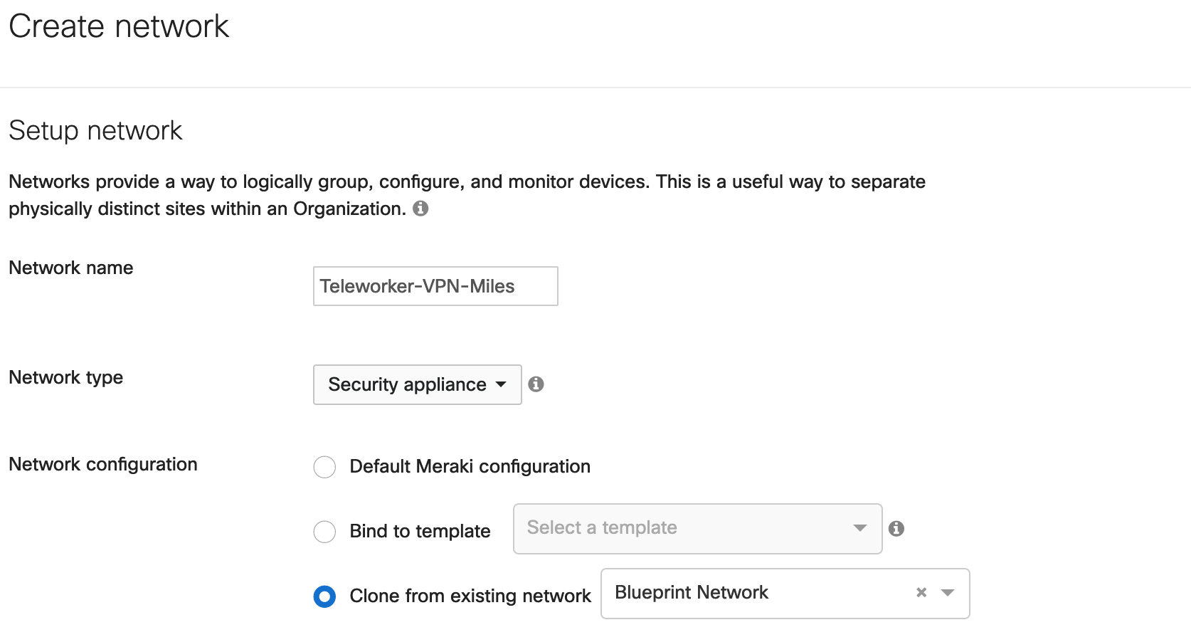
Step 3. Enter a Network name and make sure it clearly describes its purpose (e.g. “Teleworker-VPN-Miles”) and click the Add button
Step 4. Set the Network type to Security appliance, change Network configuration set to Clone from existing network and select the Blueprint Network from the list.
Step 5. Select a “Teleworker Gateway or WAN Appliance” from the bottom to add to this network. Then scroll down and click Create network.
Blueprint Teleworker Wireless Configuration (Wireless Only)
This section covers the wireless configuration piece of the reference network. Depending on the user equipment being deployed, it may be desired to create two VLAN’s, one dedicated to Data (laptop, mobile devices etc) and a second dedicated to wireless phones. It is highly recommended to perform a pre-install RF survey as outlined in the Wireless VoIP QoS Best Practices document. Below are the steps to configure your Wireless only configuration for the Blueprint network.
Step 1. Configure a dedicated SSID for voice by navigating to the Wireless tab and selecting SSIDs
Step 2. Change the Status of SSID 1 to Enabled. Rename the SSID. Use a name that describes its purpose (e.g. “CiscoTeleworker” or “CiscoVoIP” etc)
Step 3. Change the SSID Security to WPA2 PSK. Enter a WPA Key for clients to connect to the SSID, and change WPA encryption mode to WPA2 only. If 802.1x is desired for wireless, select WPA2 Enterprise then under Authentication select My RADIUS server and input the organizations RADIUS servers IP addresses.
Step 4. Change Addressing and traffic to the VPN: tunnel data to a concentrator. Select the Concentrator you want to tunnel the data to ( you will need to have a Meraki VPN Concentrator in your organization to select). Select Full tunnel: tunnel all traffic. Once the template is applied to the network you can “Test connectivity”
Step 5. Configure security for your SSID(s) by navigating to the Wireless tab and selecting Firewall & traffic shaping. Select the SSID to have changes applied. You can set firewall rules (L3/4/7 based rules) By Default voice is prioritized.
Step 6. Ensure that the Concentrator has the required DHCP configurations in place for phones to get their needed configurations.

Blueprint New Network Creation (Wireless only)
After the blueprint network is created, we can now create new networks by cloning them from the Blueprint network:
Step 1. Log in to the Cisco Meraki dashboard as an organization administrator
Step 2. Select Create a new network from the Network dropdown
Step 3. Enter a Network name and make sure it clearly describes its purpose (e.g. “Teleworker-Wireless-VPN-Miles”) and click the Add button
Step 4. Set the Network type to Wireless, change Network configuration set to Clone from existing network and select the Blueprint Network from the list.
Step 5. Select an "Access Point” from the bottom to add to this network. Then scroll down and click Create network.
Meraki Systems Manager (Unified Endpoint Management)
If your deployment includes soft clients (Webex Meetings, Webex Teams, Jabber), you can simplify the deployment and management of these endpoints by deploying Meraki Systems Manager to manage the endpoints, and to deploy the soft clients to them. This section walks through the process of creating the Systems Manager network and basic configuration of these features.
Network Creation
After a dashboard account and organization have been created:
Step 1. Log in to the Cisco Meraki dashboard as an organization administrator
Step 2. Select Create a new network from the Network dropdown
Step 3. Enter a Network name and make sure it clearly describes its purpose (e.g. “Systems Manager”) and click the Add button
Step 4. Leave Network type set to EMM (Systems Manager), leave Network configuration set to Default Meraki configuration, then scroll down and click Create network.
Step 5. Select Apps from the Systems Manager tab.
Step 6. Click Add app, then select the App platform. See Table 2 of the Appendix for application details.
Step 7. Select Devices from the Systems Manager tab. Click the type of device corresponding with the device that you want to manage.
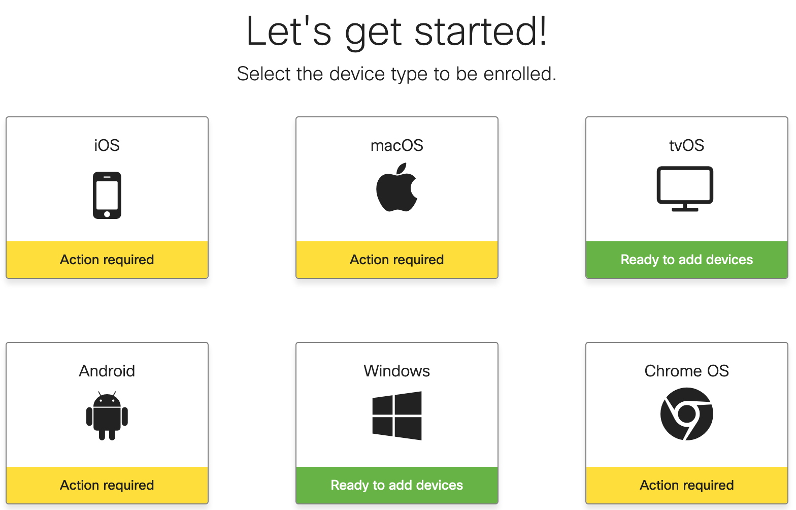
Step 8. (Windows) Download the Agent (required for software distribution via Systems Manager) and Install it.
Step 9. (macOS) Follow the steps to activate APNS through Apple. Download and install the Agent manually or add Systems Manager as an App (in the Add app window, select macOS, then SM agent and click Next).
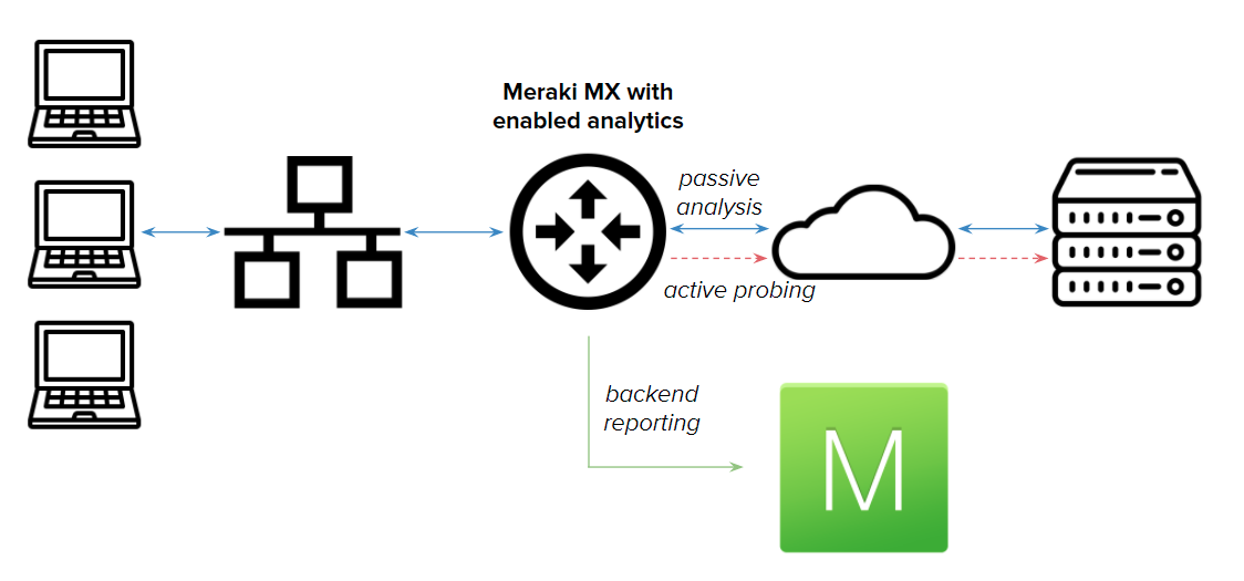
Meraki Insight
The Meraki Insight product is designed to give Meraki customers an easy way to monitor the performance of Web Applications and WAN Links on their network and easily identify if any issues are likely being caused by the network or application. The goal of Meraki Insight is to provide end-to-end visibility to the customers and make sure they have assurance for the mission-critical traffic of the network.
Enabling and Disabling Meraki Insight
To Enable Meraki Insight on a network:
Step 1. Ensure the necessary Licensing is available
Step 2. Select the checkbox next to the Network where Insight should be enabled
Step 3. Click 'Add network(s) to Insight' at the top left of the table to Enable Meraki Insight on the selected Network(s)
To Disable Meraki Insight on a network:
Step 1. Select the checkbox next to the Network with Insight currently enabled
Step 2. Click 'Remove network(s) from Insight'
Configuring Meraki Insight for VoIP
After a dashboard account and organization have been created:
Step 1. Log in to the Cisco Meraki dashboard
Step 2. Select VoIP Health from the Insight tab
Step 3. Select Configure VoIP servers on the pup-up
Step 4. Input the Provider name and the Hostname or IP. Repeat this step to add additional VoIP Servers
Monitoring Meraki Insight for VoIP
Once you provide the servers you’d like to monitor, you’ll be able to see an org-wide view of performance:
Step 1. Select VoIP Health from the Insight tab.
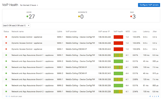
Clicking on any row will take you to a drill-down view with detailed performance information:
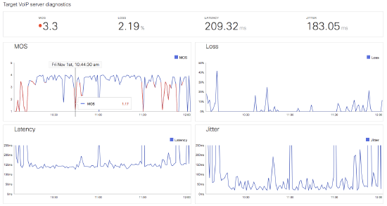
For further details regarding the capabilities of Meraki Insight, see the Meraki Insight Introduction article.
Appendix
Table 1 – Cisco Meraki devices technical specifications and sizing guide
|
Teleworker Site (with LTE Backup) Z models |
Teleworker Site (with LTE Backup) MX models |
|||
|
Z-Series Model |
Z3 |
Z3C |
MX64, 65, 67, 68 |
MX67c / 68c models |
|
Stateful Firewall Throughput |
100 Mbps |
100 Mbps |
MX64/65 250 Mbps MX67/68 450 Mbps |
MX64/65 250 Mbps MX67/68 450 Mbps |
|
Maximum VPN Throughput |
50 Mbps |
50 Mbps |
MX64/65 100 Mbps MX67/68 200 Mbps |
MX64/65 100 Mbps MX67/68 200 Mbps |
|
WAN Interfaces (Dedicated) |
1 x GbE RJ45 1 x USB (cellular failover) |
1 x GbE RJ45 1 x Integrated CAT 3 LTE Cellular Modem (cellular failover) 1 x USB (cellular failover) |
MX64 1 GbE Dedicated RJ45 MX65 2 GbE Dedicated RJ45 MX67 1 GbE Dedicated RJ45 MX68 2 GbE Dedicated RJ45 1 x USB (cellular failover) |
MX67 1 Dedicated RJ45 MX68 2 Dedicated RJ45 1 x Integrated CAT 6 LTE Cellular Modem (cellular failover) 1 x USB (cellular failover) |
|
LAN Interfaces |
4 x GbE RJ45 1 x PoE (802.3af, 15.5W) |
4 x GbE RJ45 1 x PoE (802.3af, 15.5W) |
MX64 4 GbE RJ45 (1 Opt WAN) MX65 12 GbE RJ45 (2 x PoE+) MX67 4 GbE RJ45 (1 Opt WAN) MX68 12 GbE RJ45 (2 x PoE+) |
MX64 4 GbE RJ45 (1 Opt WAN) MX65 12 GbE RJ45 (2 x PoE+) MX67 4 GbE RJ45 (1 Opt WAN) MX68 12 GbE RJ45 (2 x PoE+) |
|
Integrated Wireless |
4 SSIDs WiFi 5 (802.11a/b/g/n/ac, 2.4/5.0GHz, 2x2 MU-MIMO) |
4 SSIDs WiFi 5 (802.11a/b/g/n/ac, 2.4/5.0GHz, 2x2 MU-MIMO) |
4 SSIDs WiFi 5 (802.11a/b/g/n/ac, 2.4/5.0GHz, 2x2 MU-MIMO) |
4 SSIDs WiFi 5 (802.11a/b/g/n/ac, 2.4/5.0GHz, 2x2 MU-MIMO) |
Note: The recommended models for sizing and are based on models available at the time of publication for this document. This list will not be updated with new models. For the most up-to-date sizing guide information, please refer to the Meraki Z-Series and MX-series Data Sheets.
Table 2 – Systems Manager Application Configuration
|
Windows Apps |
Cisco Jabber |
Webex Meetings |
Webex Teams |
|
Name |
Cisco Jabber |
Cisco Webex Meetings |
Webex Teams |
|
Identifier |
Random UUID Here |
Random UUID Here |
Random UUID Here |
|
Icon URL |
|||
|
Vendor |
Cisco Systems, Inc. |
Cisco Systems, Inc. |
Cisco Systems, Inc. |
|
Version |
12.8.0.51973 |
40.2.7.7 |
3.0.15036.0 |
|
Description |
Cisco Jabber |
Cisco Webex Meetings |
Webex Teams |
|
App Download/URL |
|||
|
Install Arguments |
ACCEPT_EULA=TRUE ALLUSERS=1 |
|
macOS Apps |
Cisco Jabber |
Webex Meetings |
Webex Teams |
|
Name |
Cisco Jabber |
Cisco Webex Meetings |
Webex Teams |
|
Identifier |
com.cisco.jabber |
com.webex.meetings |
com.webex.teams |
|
Icon URL |
|||
|
Vendor |
Cisco Systems, Inc. |
Cisco Systems, Inc. |
Cisco Systems, Inc. |
|
Version |
12.8.0 |
2003.0506.4002.7 |
3.0.15015.0 |
|
Description |
Cisco Jabber |
Cisco Webex Meetings |
Webex Teams |
|
App Download/URL |
|||
|
Install Arguments |
Note: The versions and URLs are based on models available at the time of publication for this document. This list will not be updated with new software releases. For the most up-to-date release information, please consult documentation for the specific collaboration product.
Highest rated
(rating)Recently updated
(date updated)Recently added
(date created)