
MX and MS Basic Recommended Layer 3 Topology
Overview
This document will go over a general reference topology that can be used when designing your network. It includes a layer 3 device that handles client VLANs downstream of the MX device.
Correct Topology
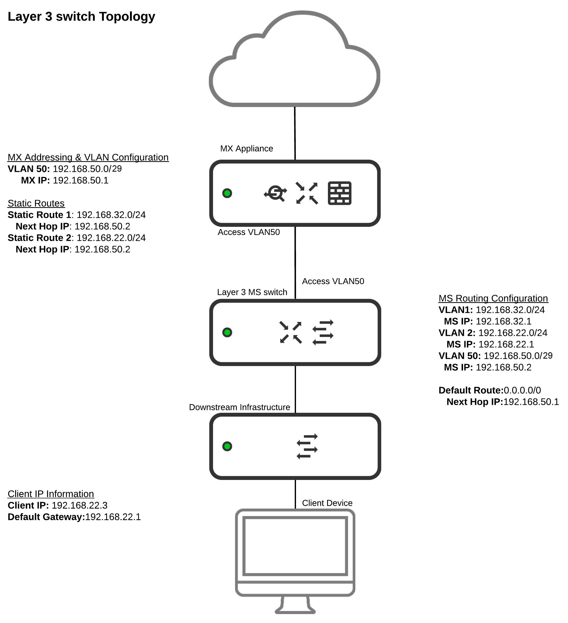
In this topology:
- Client VLAN 1 and VLAN 2 are only defined on a single layer 3 device (Layer 3 MS switch).
- Client devices have a default gateway of the layer 3 device the VLAN has been defined on.
- A single transit VLAN 50 is used to allow for communications between the MX and downstream subnets.
- For downstream infrastructure and client subnets, static routes are configured on the MX. The next hop IP address is that of the layer 3 switch's IP on the transit VLAN 50.
- The layer 3 switch is configured with a default route with a next hop IP address of the MX's IP on the transit VLAN.
- The ports used to connect the MS and MX are both properly defined as being on VLAN 50, the transit VLAN.
Keep in mind that the management/LAN interface (Switching > Switches > LAN IP) of the switch and L3 interface are separate. Both interfaces can exist on the same VLAN/subnet, but the management interface must have a different IP than the L3 interface. Referring to the above diagram, the L3 switch cannot have the management IP as 192.168.50.2 as it is configured to be one of the L3 interfaces.
The management IP for the L3 switch cannot have the gateway pointed to one of its own L3 interfaces as it will not be able to check in using the assigned management IP when the gateway is pointed to itself. Referring to the above diagram, the L3 switch can either have the management IP from VLAN 50 (as long as it is routable to the internet) with the gateway pointing to 192.168.50.1 or you can have another VLAN created on the MX that only serves for the management of the L3 switch.
How is traffic routed given the above configuration?
In each scenario below, traffic is always sent from the downstream client - 192.168.22.3.
- If traffic is destined to 192.168.22.22
- The traffic is forwarded at layer 2 by the downstream switching infrastructure. This traffic is not processed by the layer 3 switch, or by the MX.
- If traffic is destined to 192.168.32.14
- The traffic is received by the layer 3 switch and routed directly to 192.168.32.14. This traffic is not processed by the MX.
- If traffic is destined to 216.58.194.206
- The traffic is received by the layer 3 switch and routed to the MX via the transit VLAN. This traffic is received by the MX on VLAN 50.
- The MX will then compare the traffic against any other filtering rules (e.g. layer 3 firewall rules, layer 7 firewall rules, content filtering policies, etc.). If the traffic does not match any block rule configure on the MX, the traffic will be NATed and sent to the Internet.
For information on IP spoofing and how it functions in situations where the network is not correctly designed please refer to our article on IP Source Address Spoofing Protection