

Meraki Assurance Overview Page
Click 日本語 for Japanese
What is Assurance Overview?
Assurance Overview is a set of assurance features that enable network administrators to understand the overall health of their network across their entire stack and provide quality experiences to their customers. The goal is to empower network administrators to easily monitor their network health across the full stack and quickly identify and troubleshoot problematic areas.
The Assurance Overview page can be found under Assurance > Analytics > Assurance Overview. It consists of three tabs: Experience metrics, Network services, and Network health score. Each provides a useful perspective on network health and user experience.
Learn more with these free online training courses on the Networking Learning Hub:
Goal of the Assurance Overview
-
Create a unified assurance experience.
-
Improve network administrator's experience so they can accurately evaluate and maintain quality of experiences for end-users.
-
Improve end-user’s experience so they can securely, seamlessly, and reliably access business critical network resources.
Providing feedback is as easy as selecting the “Give Feedback” blue tab on the right side of screen (make sure ad blockers are off for this page) and the “Give your feedback” button in the lower right corner of the screen (See figures below).


Experience Metrics
What are Experience metrics?
 Experience metrics is currently in beta and requires a minimum firmware of MR 27 for wireless; To opt in, please navigate to Organization-wide > Configure > Early Access.
Experience metrics measure wireless end-to-end user experience on the selected network by tracking every user's experience every minute and quantifying a poor experience. It provides a view of connected clients with hover functionality and the ability to select a time range to review end user metrics. Each metric is given a status, failure contributor, and failure rate.
For information on Organization-Wide Experience Metrics, please visit the Organization Assurance Overview documentation.
For API information (beta), please visit Cisco DevNet Documentation.

The connected clients timeline (see figure above) provides a visualization of how many clients were connected to the network during the selected time frame, with the last 3 days being the default preset. Each preset will highlight a specific time frame within the selected preset as follows: the last 2 hours highlights the most recent 15 minutes, the last day highlights the most recent 2 hours, the last 3 days highlights the most recent 8 hours, and the last week highlights the last 24 hours. The x-axis displays the selected time frame, while the y-axis a view of client count. The timeline automatically refreshes as new data comes in unless the user manually toggles off auto refresh.
Health Thresholds

Health thresholds measure the overall status of the network's health based on fixed thresholds. The goal of heath thresholds is to give an overview of how the network is doing and assign it a status of good, fair, or poor.
The health status of each experience metric is determined by fixed thresholds:
- 95-100 is good
- 90-94 displays a fair status
- 0-89 displays a poor status
Healthy experience metrics (score of 90% - 100%) are not assigned a status. This is to focus attention on where it is needed and reduce visual noise.
Individual Experience Metric Thresholds
In addition to health thresholds, each experience metric has their own threshold based on the specific metric it is measuring.
Current Metrics and their respective thresholds are as follows:
- For successful connects, including wired (switches) and wireless (access points), clients that attempt a connection can either pass or fail. Each client pass and failure is averaged for the selected time period, and then averaged again across all the network's clients.
- For time to connect, clients are expected to connect to the network in 3 seconds or less. If the client fails to connect in 3 seconds or less, it will be marked as a failure and negatively impact this metric.
- For channel availability, a client that is connected to an AP under 70% overall utilization and less than 40% combined non-Wi-Fi and co-channel interference is considered a healthy client. If a client is connected to an AP over 70% overall utilization and more than 40% combined non-Wi-Fi and co-channel interference, this metric will be negatively impacted.
- For coverage, a client that has a total signal-to-noise ratio (SNR) at or above 20 dB has adequate coverage. If the clients SNR is lower than 20dB, this metric will be negatively impacted.
Failure Contributors and Sub-contributors
Failure contributors help users understand the underlying causes of a degraded experience metric. Some contributors also include sub-contributors to help further determine the cause. Failure contributors will always sum to 100%.
The highest failure contributor (and sub-contributor, if applicable) will be highlighted in red if it falls below “good”.
Wired successful connections
Sub-contributors are currently supported on Catalyst switches; sub-contributor support on all failure contributors for MS switches will be made available March 2027*

Wired successful connections measure the rate at which wired clients connected to switches successfully establish connections, measuring PoE, Authentication, DHCP, and Link success.
- PoE - Highlights failed or constrained Power over Ethernet delivery from the switch to the client.
- Sub-contributors:
- Inline power denied
- Faulty hardware
- Overdrawn power
- Sub-contributors:
- Link - Tracks whether the client establishes and maintains a physical connection to the switch port.
- Sub-contributors:
- Admin disabled
- Error disabled
- Sub-contributors:
- Authentication - Surfaces access failures such as invalid credentials or an unavailable authentication server.
- Sub-contributors:
- Invalid credentials
- RADIUS server issues
- Handshake timeout
- Security violation
- Sub-contributors:
- DHCP - Tracks whether a client receives a valid IP address during connection.
- Sub-contributors:
- No DHCP response
- NAK or denial
- Sub-contributors:
The DHCP wired sub-contributor requires Catalyst switches to run firmware version OS XE 26.1.2
Wireless successful connections

Wireless successful connections measure the rate at which wireless clients successfully establish fresh connections across association, authentication, IP assignment, and DNS resolution phases.
- Association - A device fails to associate if there is a mismatch between the device's supported 802.11 capabilities and the access point’s configurations, or if the access point (AP) has reached its maximum configured client limit.
- Sub-contributors:
- Block listed client
- Feature conflict
- AP overloaded
- Roaming failures
- Cipher mismatch
- Other
- Sub-contributors:
- Authentication - Failure occurs when the device provides incorrect security credentials, such as a wrong Pre-Shared Key (PSK) or invalid 802.1X/EAP certificates, preventing the establishment of a secure session.
- Sub-contributors:
- Handshake timeout
- Invalid credentials
- RADIUS server issues
- AAA config errors
- Other
- Sub-contributors:
- DHCP - Tracks whether a client receives a valid IP address during connection.
- Sub-contributors:
- Slow response
- Client not responding
- NAK or denial
- No DHCP response
- Proxy/relay config
- Sub-contributors:
- DNS - Tracks whether a client receives a valid DNS server during connection
- Sub-contributors:
- DNS server unreachable
- Slow response
- Sub-contributors:
Time to connect

Time to connect measures wireless client onboarding latency across association, authentication, IP assignment, and DNS resolution phases. Wireless clients should successfully establish fresh connections to the network in 3 seconds or less.
- Association - A device fails to associate if there is a mismatch between the device's supported 802.11 capabilities and the access point’s configurations, or if the access point (AP) has reached its maximum configured client limit.
- Authentication - Failure occurs when the device provides incorrect security credentials, such as a wrong Pre-Shared Key (PSK) or invalid 802.1X/EAP certificates, preventing the establishment of a secure session.
- DHCP
- DNS
Channel availability

Channel availability measures RF channel capacity to determine whether wireless clients can reliably pass traffic over shared airtime. A wireless client has sufficient channel availability if its AP radio operates on a channel with less than 70% overall utilization and less than 40% combined non-Wi-Fi and co-channel Wi-Fi interference.
- Co-Channel interference - A client fails when multiple access points or devices operating on the same frequency channel compete for airtime, increasing contention and raising the noise floor, which degrades the effective signal quality.
- Sub-contributors:
- Out-of-network
- In-network
- Sub-contributors:
- Non-Wi-Fi Interference - Clients will fail when when radio frequency from non 802.11 sources overlap with Wi-Fi channels, creating noise which prevents clients from successfully decoding data packets. Common non-802.11 sources include microwaves, Bluetooth devices, and motion sensors.
- High Traffic - A client will fail when the volume of data being transmitted by all devices on a channel exceeds the available airtime, leading to excessing packet collisions, latency, and dropped connections from network congestion.
- Sub-contributors:
- High client count
- High Bandwidth clients
- Sub-contributors:
Coverage

Coverage measures the wireless signal quality of connected clients across the network. A wireless client has adequate coverage if its measured signal-to-noise ratio (SNR) is 20dB or greater.
- Transient weak client signal - A client fails when its own transmit power is insuffcient to reliably reach the AP, leading to an asymmetric link where the client can hear the AP, but the AP cannot hear the client. This is often caused by a client’s physical distance to an AP.
- Insufficient AP density - Failure occurs when there are too few APs installed in a physical space, creating "dead zones" or gaps in the radio frequency (RF) environment where signal strength drops below usable levels.
- Admin power restriction - A client fails when the AP’s transmit power is manually capped or restricted by an administrator to a level that is too low to penetrate obstructions or cover the intended floor area, resulting in poor SNR at the cell edge.
- Sticky client - A device that persistently remains connected to an underperforming access point despite the availability of better signal options, resulting in a consistent degradation of the user experience.
Failure rate measures how frequent the individual contributing line item within the tab the user is viewing (e.g. SSID, band, etc.) is failing relative to itself. This indicates whether failures are isolated or are more broadly distributed.
Selecting any of the above metrics will allow you to drill into the metric further though Insights view or Investigation view.
Insights view provides a summary of the selected metric’s network impact as well as visual representation of success and the contributor failures. Additionally, it will intelligently highlight the fault domain(s) for the experience metric, helping guide users in troubleshooting efforts.
The Investigation view lays out associated data related to the selected experience metric to identify top servers, access points, clients, and other information impacted by the failures.
If a client listed within experience metrics is not hyperlinked to a dedicated client page, this is due to the client never successfully completing the connection process and is expected behavior.
Summary and Investigations

To dig even deeper into the causes of experience metric degradations, within each contributor and sub-contributor exists the summary and investigations view.
The summary panel provides key insights on the selected contributors and/or sub-contributors, delivering details such as impacted client totals, and specifics on the selected contributors and/or sub-contributors, such as radio information and if they correlate accross multiple SSIDs, servers, switches or APs.
The investigation panel provides interactive filtering that allows users to drill down into SSIDs, bands, switches, VLANs, access points, clients, client types, and client OS to best correlate and identify the blast radius of the selected issue.
Network Services

Network services is currently in beta and requires a minimum firmware of MR 28
The network services tab provides insight on 3 key services: DHCP, DNS, and RADIUS. It surfaces passive data on how the network is performing from the user’s perspective, including query response time, DHCP handshake exchanges, and RADIUS authentication round trip time. Metrics are available in aggregate and per server.
Overall Thresholds
The services are classified as healthy based on the following thresholds:
- DHCP: 80% of clients are able to successfully obtain an IP address from the configured DHCP server(s).
- DNS: 80% of clients are able to successfully resolve DNS queries from the configured DNS server(s).
- RADIUS: 80% of clients are able to successfully authenticate through the configured server(s).
If less than 80 percent of clients are unable to successfully render from any of the 3 above services, their status will change from “Healthy” to “Degraded”.
Troubleshooting Network Issues with Experience Metrics and Network Services
Use Experience Metrics (XMs) to identify where the user experience is failing, then use Network Services to determine whether DHCP, DNS, or RADIUS is contributing to the issue. Experience Metrics is currently in early access; to enable, please navigate to Organization > Configure > Early Access and opt in to Wireless Experience Metrics.
Recommended troubleshooting workflow:
1. Define the scope and time of the incident.
Navigate to Assurance > Analytics > Assurance Overview, select the affected network, and set the time range to when users experienced the issue. A narrow time window makes it easier to correlate client failures, service degradation, and configuration changes.
2. Identify the affected Experience Metric.
Review the four wireless Experience Metrics:
- Wired successful connections: PoE, Link, Authentication, or DHCP failures.
- Wireless successful connections: Association, authentication, DHCP, or DNS failures.
- Time to connect: Onboarding taking longer than 3 seconds.
- Channel availability: High utilization, Wi-Fi contention, or non-Wi-Fi interference.
- Coverage: Client SNR below 20 dB.
3. Follow the leading failure contributor.
Select the degraded metric and review its contributors and sub-contributors.
Use the:
- Summary to understand the number of affected clients and whether the issue crosses multiple SSIDs, APs, switches or servers.
- Investigation table to filter by SSID, band, AP, switches, VLANs, client, client type, or operating system.
This establishes the blast radius and helps distinguish a widespread infrastructure problem from an isolated client or AP issue.
4. Correlate the finding with Network Services.
Review DHCP, DNS, and RADIUS in aggregate and per server. Meraki marks a service Healthy when at least 80% of clients successfully complete the corresponding operation.
- If an XM points to DHCP, DNS, or authentication and the matching service is degraded, investigate the affected server and the network path to it.
- If the service is healthy but the XM is degraded, narrow the investigation to the affected SSID and AP, VLAN and switch, client type, credentials, or configuration.
- If Channel Availability or Coverage is degraded while all services are healthy, focus on RF conditions rather than DHCP, DNS, or RADIUS.
5. Check the Configuration Changes timeline.
Look for changes made shortly before the degradation began. The timeline can link directly to a filtered organization change log. Relevant changes include SSID access control, AP settings, VLAN and DHCP configuration, switch ports, access policies, ACLs, and routing.
6. Validate the recovery.
After remediation, use the same network, filters, and comparable time window to confirm that:
- The Experience Metrics improve.
- The leading contributor’s failure rate decreases.
- Fewer clients are affected.
- The associated network service returns to or remains Healthy.
Common Network Issues
Issue 1: Corporate wireless clients cannot authenticate
Symptom: Employees report that the corporate SSID repeatedly prompts for credentials or fails to connect.
Investigation:
- Open Experience Metrics and review Successful connects and Time to connect.
- Drill into Authentication. If RADIUS server issues, handshake timeouts, or AAA configuration errors are leading contributors, note the affected SSID, APs, and clients.
- Open Network Services > RADIUS and compare individual servers. A single server showing lower success or higher round-trip time may indicate server load, reachability, firewall, shared-secret, certificate, or policy problems.
- If all RADIUS servers are healthy, filter the XM investigation by client OS or device type. A concentrated failure pattern may indicate invalid credentials, expired certificates, or a client compatibility issue rather than a service outage.
- Check the configuration timeline for recent access-control or SSID changes, remediate the identified cause, and confirm that authentication failures decline.
Issue 2: Wireless performance is poor in one area
Symptom: Users in conference rooms experience slow or intermittent Wi-Fi, but they can still obtain an IP address and reach applications.
Investigation:
- Open Experience Metrics and review Channel availability and Coverage for the reported time.
- Drill into contributors such as high client count, high-bandwidth clients, co-channel interference, non-Wi-Fi interference, low SNR, or sticky clients.
- Use Investigation filters to determine whether the failures are concentrated on particular APs, bands, or physical areas.
- Confirm that DHCP, DNS, and RADIUS remain Healthy. This helps rule out shared network services and keeps the investigation focused on RF conditions.
- Review AP density, channel utilization, transmit-power settings, client distribution, and possible interference sources. After making the appropriate RF adjustment, verify that the affected XM and client impact improve.
Issue 3: A wired PoE endpoint does not come online
Symptom: An IP phone, security camera, or wireless access point connected to a switch port does not power on or establish network connectivity.
Investigation:
-
Open Experience Metrics and review Wired Successful Connections for the reported time. Drill into the degraded metric to identify whether PoE, Link, Authentication, or DHCP is the leading failure contributor.
-
If PoE is the leading contributor, review the reported sub-contributors:
- Inline power denied: Confirm that PoE is enabled on the port and that sufficient power remains in the switch’s PoE budget.
- Overdrawn power: Confirm that the endpoint’s requested power does not exceed the port or switch limit.
- Faulty hardware: Inspect or replace the cable, test the endpoint on another known-good port, and verify the endpoint’s power requirements.
Treat a power-off event as a failure only when the connected endpoint requires PoE. A non-PoE endpoint may legitimately appear as not drawing power.
-
If Link is the leading failure contributor, check whether the port is administratively down or error-disabled. Review the switch-port configuration and status, then investigate the reported error-disabled cause before re-enabling the port.
-
Use the Summary and Investigation views to determine the scope of the issue. Filter by switch, port, VLAN, client type, or client operating system:
- A single affected port usually indicates a port, cable, or endpoint/client problem.
- Several affected ports on one switch may indicate a PoE-budget, switch configuration, or hardware issue.
- Failures across multiple switches, but the same VLAN may indicate an authentication, DHCP, or upstream service problem.
If the failure occurs before the switch learns the endpoint’s MAC or IP address, the endpoint might not have a client link. In that case, continue the investigation using the affected switch and port.
-
If Power and Link are healthy, follow the next failing contributor:
- For Authentication, investigate invalid credentials, handshake timeouts, security violations, or RADIUS server issues. Compare the result with Network Services > RADIUS.
- For DHCP, investigate No DHCP response or NAK or denial. Confirm the port’s VLAN assignment, DHCP scope availability, relay configuration, and server reachability; then compare the result with Network Services > DHCP.
-
Review the Configuration Changes timeline for switch-port, access-policy, VLAN, ACL, authentication, or routing changes made immediately before the failures began. After remediation, reconnect the endpoint and confirm that Wired Successful Connections improves, the contributor’s failure rate decreases, and the endpoint receives power, establishes link, authenticates when required, and obtains a valid IP address.
Network Health Score
 The network health score tab consists of multiple impacts sections, including Network health score, Clients, Network devices, Infrastructure connectivity, and Applications.
- The Network health score module shows the a health score, which is a combined score taking into account different weighted aspects of network health to give an overall health of the environment
- The timeline next to it gives you a look at the network health over a time span governed by the time selector at the top
- Next are the impact sections which give you a view as to how many clients are impacted for each type of alert that is/has been active in the system.
- The Client module breaks this down by connection type, wireless, remote, and wired
- The Network devices module shows context for the Cisco first party devices in the network
- The applications module provides information on how large the client impact is for errors in the Application environment. This module is sourced from Thousand Eyes data that is entered elsewhere in the Dashboard for web services that you are tracking.
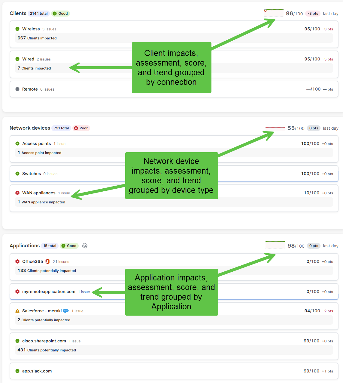
Client Impact Module
Note: All the columns may not be filled with information at this time...THIS IS NOT A BUG...More data and information will be added over time to the Impacted Clients tables.
Note: The minimum required firmware version for the wireless client metrics on the Network Assurance Overview page and any page displaying wireless health and monitoring information is MR 27.x See MR Mixed Firmware Networks for more details.
- You can highlight and select one of the buckets in the modules and this will open a side drawer that slides in from the right of the screen, with more details about that specific bucket.
- In this side drawer you’ll be given a list of specific metrics and a further breakdown of the client impact.
- Clicking on one of the metrics will provide further details, drilling down to the actual client list level.
- At the top you’ll also see a pie chart visualization that provides further visual breakdown to help assess priority.
- Here you can see details on the clients or be taken to the client details page to get more information on that client.
- On the details page there are search and filter boxes to help refine what you are looking for.

- Clicking on one of the client links under impacted clients in the detail side drawer will take you to the client detail page
- Here you get a full picture of what Dashboard and Assurance know about the client to aid in troubleshooting.
Note: All the columns may not be filled with information at this time...THIS IS NOT A BUG...More data and information will be added over time to the Impacted Clients tables.
Failure Types Explained
| Reserved | System reserved failure type space |
| Unspecified | Failure type does not match any defined type in the system |
| Previous authentication no longer valid | The authentication credentials or tokens used in a prior session have expired or been revoked, requiring re-authentication |
| Deauthenticated because client left coverage area | Client was removed from the AP as it has moved away from it's service area |
| Disassociated due to inactivity | This is a normal behavior where the access point disassociates a client that has not transmitted or received data for a timeout duration to free up resources |
| AP unable to handle all currently associated clients | Involves checking AP capacity and busy status, client behavior, network configuration, client distribution, uplink speed, and multicast traffic handling |
| Class 2 frame received from non-authenticated client | Received a Management frame like Association Request, Re-association Request, and Disassociation, from a non-authenticated client |
| Class 3 frame received from non-associated client | Client attempted to transfer data before it was associated. |
| Disassociated because client left coverage area | Client was removed from the AP as it has moved away from it's service area |
| Client requesting association is not authenticated | Client not authorized yet, still attempting to associate with an access point. |
| Unsupported capabilities | A feature is not supported |
| Unacceptable values in the supported channels element | Client was disassociated because the information in the Supported Channels element was unacceptable during the association or authentication process |
| Unsupported authentication algorithm | Authentication method or algorithm configured is not supported or allowed by the Cisco device or software version in use |
| Challenge failure | A failure during the authentication process between a wireless client and the network, often involving the exchange of challenge messages used to verify credentials. |
| Timeout waiting for next frame in sequence | Indicates a delay or failure in receiving the expected next frame in a data transmission sequence |
| AP unable to handle additional clients | AP is busy or has reached capacity and can no longer service additional clients |
| Client does not support short preamble | Client requires the use of a long preamble for wireless communication |
| Unacceptable power capability IE | The client's Association request was rejected because the information in the Power Capability Information Element is unacceptable. |
| Temporary refusal | Temporarily refuses, fails to join, or associate with a Wireless LAN Controller, reasons including regulatory domain mismatches, firmware issues, configuration errors, or network conditions |
| 802.11w robust management frame policy violation | Management frame does not comply with the 802.11w protection requirements, such as missing the MIC or failing integrity checks |
| Missing ACKs due to excess frame loss | Acknowledgment frames are not being received because too many data frames are lost or corrupted during transmission |
| Client left the AP | The client device has disassociated or disconnected from the access point |
| Cannot honor requested traffic specification (TSPEC) | A QoS-capable client requests network resources from a Wireless Access Point (WAP) via TSPEC, but the WAP cannot approve the request |
| Invalid information element | A data element or property in a protocol does not conform to expected or defined standards, causing errors or vulnerabilities |
| Invalid group cipher | A mismatch or unsupported cipher suite configuration often between VPN endpoints |
| Invalid pairwise cipher | A mismatch or unsupported cipher suite used in the encryption negotiation between devices, often in VPN or MACsec configurations |
| Invalid authentication and key management protocol (AKMP) | Problems in the authentication and key management process for secure communication protocols; misconfiguration, unsupported capabilities, or key derivation failures |
| Invalid 802.11r Fast Transition IE | The Fast Transition Information Element (IE) in the reassociation request or response frames may be malformed or inconsistent. |
| Invalid 802.11r Fast Transition action frame count | An invalid FT action frame count error indicates that the expected number of FT action frames was not received or that frames were malformed or out of sequence during the roaming process. |
| Invalid pairwise master key identifier (PMKID) | Problem with the PMKID handshake mechanism used in WPA2 wireless security for fast roaming |
| Invalid mobility domain | Mobility domain name or ID not properly configured or inconsistent across the network elements. |
| Mesh Peering Close requested | A request to close or terminate an existing peering connection between mesh nodes. |
| Anti-clogging token required | A token tied to a station's MAC address that proves the client is legitimate before the server allocates resources for it to prevent DoS attacks. |
| Unsupported finite cyclic group | Authentication is rejected because the offered finite cyclic group is not supported |
| Unacceptable values in the power capability element | This element do not meet the access point's requirements or are outside acceptable ranges, the AP will disassociate the client. |
| Message integrity code (MIC) failure | When the integrity check on a wireless frame fails, indicating that the message may have been altered or corrupted during transmission |
| 4-way handshake timeout | Timeout occurs when a client ignores the M1 or M2 messages sent by the Access Point (AP) during the 4-way handshake process |
| Group key handshake timeout | Timeout ensures that if the handshake does not complete within the specified time, the process is terminated to avoid indefinite waiting and potential security risks |
| RADIUS authentication rejected by server | RADIUS server has received the Access-Request from the Network Access Server (NAS) but has denied the authentication based on the credentials or policies configured |
| RADIUS timeout | Device does not receive a response from the configured RADIUS server within the expected timeout period |
| EAPOL: Timeout waiting for client EAP response | Authentication process is waiting for a response from the client during the Extensible Authentication Protocol over LAN (EAPOL) exchange, but the client does not respond within the expected time frame |
| EAPOL: 4-way handshake error | Error during the key exchange process between a wireless client and an access point (AP) in WPA/WPA2 or WPA3 authentication |
| EAPOL: Invalid message integrity code (MIC) | Problem during the 4-way handshake in the 802.1X authentication process, often caused by an incorrect Pre-Shared Key (PSK) configured on the client device |
| RADIUS connection refused | The connection attempt from the client or access point to the RADIUS server was rejected |
| RADIUS timeout: Frame too long | A RADIUS packet exceeds the maximum transmission unit (MTU) size supported by the network or the RADIUS server, causing the packet to be dropped or fragmented improperly |
| RADIUS timeout: Bad frame | The RADIUS server did not respond within the expected timeout period, and the client received an improperly constructed or corrupted packet |
Network Devices Impact Module
-
Selecting one of the buckets in the Network Devices Module will open a side drawer (slide in from right) and give you context on the metrics impacting that device in the time period represented in the time filter
-
Selecting a specific metric will drill down into a list of the impacted devices for that metric.
-
Clicking on a device name in the impact list (like the client impact module) will take you to the device's detail page to get more information about the device and its current condition

Infrastructure Impact Module
Note: This is in active tiered rollout, and is being rolled gradually on a percentage basis
The infrastructure Impact Module displays aspects of the core infrastructure related to LAN, WAN, VPN and RF (WLAN). Each sub-section will open a side drawer with more context allowing for the user to drill down on the selected metric you want to get insight about.
For LAN these metrics are tracked and used for scoring
- STP (Spanning Tree protocol)
- Storm Control (Broadcast and Multicast traffic)
- VRRP (Virtual Routing Redundancy Protocol)
- Link errors
For WAN these metrics are tracked and used for scoring
- WAN Link Status
- Loss
- Latency
For VPN the Auto-VPN tunnels are tracked and used for scoring
- Connectivity
- Latency
- Usage
For RF (WLAN) 5 GHz and 6 GHz frequencies are currently tracked for scoring along with individual metrics.
- Neighbor Score
- Interference Score
- Noise Score
- Client Score
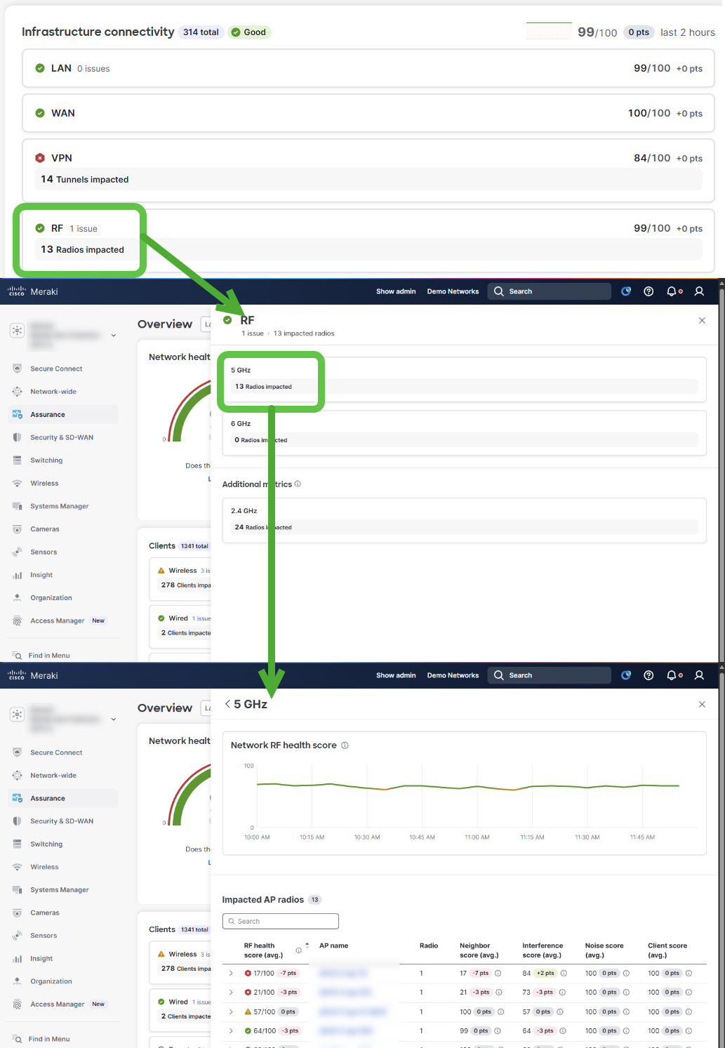
RF Scores
The individual RF metrics each have sub-components that determine the overall score.
For Neighbor Score these metrics are tracked and used for scoring:
- Co-channel neighbor
- Side-channel neighbor
- Co-channel neighbor with utilization
For Interference Score these metrics are tracked and used for scoring:
- CCA busy
- Channel interference
- Side-channel interference
For Noise Score these metrics are tracked and used for scoring:
- Channel noise
- Side-channel noise
For Client Score this metric is tracked and used for scoring:
- Low RSSI client
The resulting RF Health scores for individual APs are the lowest score from their sub-component values.
Network RF health score uses a weighted average where the weights are shown to the right of each score.
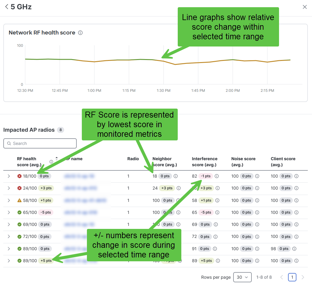
Application Impact Module
The Application Impact Module provides simplified and rich visibility into the health and current status of the customer's critical applications. This module leverages ThousandEyes data to provide active monitoring analytics.
The application module consists of two sections, the main application view, which is available on the Assurance Overview page, and the detailed information drawers, which appear on the right side of the Dashboard once they are invoked.
Note: Traffic analytics must be set to "Detailed: collect destination hostnames" under Network-Wide > Configure > General in order for information to display.
Application Monitoring with Internet Insights
ThousandEyes Internet Insights is a built-in monitoring feature for SaaS applications and is included in your dashboard experience as the default application monitoring tool. An MX Security Appliance is not required, and there is no additional licensing needed.
Each application card shows a summary of the monitored application’s status. If an outage or issue is present, it will highlight the number of potentially impacted clients and the number of issues affecting them.
It provides an overview of the network’s top 5 cloud-based applications based on usage within the last week. If an outage is detected, the application will reflect “potential outage detected”. If the same application has multiple outages, the application will include a counter displaying the total outages per application.
Note: If the ThousandEyes integration with Meraki MX Appliance is active, its additional features will be displayed instead of the Internet Insights information. For more information on the ThousandEyes with Meraki integration, please refer to the following article Meraki MX ThousandEyes Configuration Guide.
As seen in the Main Application view below, the top 5 Internet Insights monitored cloud applications are listed from highest usage (top) to lowest usage.

Application Monitoring with Active Application Monitoring
ThousandEyes Active Application Monitoring provide additional insight and configurability for application monitoring beyond the default Internet Insights capabilities by leveraging our native integration with the ThousandEyes Enterprise agent, which runs inside the Meraki MX Appliance natively and provides active monitoring data.
In the Main Application view below, all the Enterprise Agent monitored applications are listed from worst (top) to best performing as dictated by their individual score.

Requirements
- Successful onboarding and installation of the ThousandEyes agent on the Meraki MX. For more details, please refer to our Solution Requirements section in the Meraki MX ThousandEyes configuration guide.
- SDW+ Licensing
Note: Detail Application metrics like Loss, Latency, Availability are only available with the ThousandEyes Agent running on the Meraki MX.
Score breakdown

Note: Application scores are only available with ThousandEyes Enterprise Agent integration. They are not included with Internet Insights.
Blue Score: This score is the ThousandEyes-based Application score. It’s shown here without modification besides the needed aggregation and averaging to ensure that it contains all the measurements from the selected time period. Metrics that are used to calculate this score are: Packet Loss, Latency, Jitter and Application Availability (any HTTP response code from the Application greater than 400 results in the App being unavailable).
Red Score: Also known as the Customer Experience Score or Impact Score, is a score calculated based on the ThousandEyes score plus a weight that accounts for the number of potentially impacted clients. The idea is to summarize the Applications’ health and performance across the network and the impact of the outage on their users. This aggregation is also done based on the selected time period.
Points change: Show how the score has changed when compared to the previous time period. For example, if the data requested is for the last 2 hours it will show how the score has changed from the previous period of 2 hours.
Main Application View
The Main Application view provides a quick overview of the performance and health of the applications being monitored in the network. This view contains several data points that reflect the impact of any outage or performance degradation affecting the applications during the time frame specified. See an example of the Internet Insights view below:

Detailed Information Drawers
Once an application card is clicked, the detailed information drawers are opened to the right side of the dashboard. Currently, they are three levels deep and provide information following the progressive disclosure principle. These drawers allow deep diving into the ThousandEyes test data as well as all the Alerts or Issues that exist for a given application. The first drawer can be brought up by clicking on a desired application. See an example of the Active Application Monitoring view below:

First Drawer: Network Layers
The goal of the first drawer is to highlight the potential network layers where the issue or outage might exist. Currently, they are divided into two:
- Internet Layer: It focuses on network issues that are present from the location where the ThousandEyes Enterprise agent is located up to the Application server, meaning anything across the Internet. The metrics that we capture are Packet Loss and Latency across the whole path.
- Application Layer: This layer showcases any issues with the application HTTP server itself, meaning any unexpected HTTP response or undesired response time. The metrics captured are Availability (Any HTTP response code > 400 is considered unavailable) and Response Time.
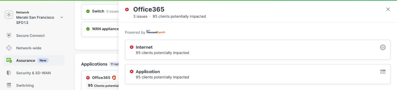
All the other metrics in the drawer are self-explanatory.
Second Drawer: Layer’s detail metrics
The second drawer provides detailed information on the value of the metrics that are captured for each layer and current or previous alerts that caused an outage or a performance degradation event. For example, for the Internet card, we see the Loss and Latency metrics and their values during the selected time period:

Most of the information on these pages is self-explanatory, but something to highlight is that on the line graphs, if the background is red, an alert was active during that time. We also provide a list of the start and end times for these alerts or issues at the bottom of the drawer. If an ongoing issue is detected, its end time will be shown as Active.
The second drawer will always include any information on triggered alerts that result in a performance issue for the network clients. If multiple alerts occur during that time and some are resolved, they will be ordered from latest to oldest, with the active alert always at the top. The third and final drawer can be accessed by clicking on one of the alerts.
Third Drawer: Client Impact and ThousandEyes Redirection
The third and final drawer focuses on showing the impacted clients by the previously selected alert. It can be accessed by clicking on one of the Alerts shown on the second drawer table.

This drawer provides information on which clients were potentially affected by the outage selected previously. It also allows redirection to the ThousandEyes Dashboard, where more information on the issue can be seen if desired. Please keep in mind that the ThousandEyes portal will require your login information if you have not already logged in.
Troubleshooting ThousandEyes data in the Assurance Overview Page
Troubleshooting the application section should be done using the same tools and methods used for general Dashboard troubleshooting, such as browser developer tools and HAR captures. If you need help please reach out to our Meraki Support team.
Configuration Changes Timeline
To streamline troubleshooting, the assurance overview page now includes a configuration change log. This feature allows users to swiftly determine if recent configuration changes might be impacting network performance. For a more in-depth analysis of a particular change, users can click on the associated hyperlink to be taken directly to the pre-filtered Organization >> Change log page.

Notes: Please note that changes only from these pages are currently tracked
- WAN APPLIANCE PAGES
- Addressing & VLANs
- Client VPN settings
- Threat protection
- Active directory
- Appliance Status
- Uplink tab
- ACCESS POINT PAGES
- Access control
- SSID availability
- Overview
- MS SWITCH PAGES
- Switch settings
- Switch ports
- Access policies
- Switch ACLs
- Routing and DHCP