
Basic SFP Troubleshooting Guide
Overview
This article is intended to provide a basic understanding and layer 1 troubleshooting steps in the event the case links do not come ON-LINE while using small form-factor pluggable (SFP) modules.
Do not look straight into an SFP light transmitter hole while it is inserted into a switch. This can cause severe damage to the eye and temporary blindness.
This guide assumes that you are using supported SFP modules/cables with your Meraki equipment. For more information on the supported accessories, refer to Small-Form Factor Pluggable (SFP) and Stacking Accessories.
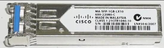
What is an SFP transceiver?
The SFP is a compact, hot-pluggable network interface module used for both telecommunication and data communications applications.
Key Concepts
Wavelength: Meraki SFP’s use 850nm, 1310nm, and 1550nm
100 Mbit/s SFP: Not supported by any Meraki device
1 Gbit/s SFP and 10 Gbit/s SFP+ supported models can be found in the SFP and Stacking Accessories documentation.
Single-Mode (SM) 1310 and 1550nm wavelength
Multi-mode (MM) 850nm wavelength
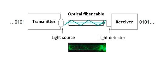
How it works
In order to establish an active link, you need both SFPs to be the same type/model and wavelength (ideally you want the same SFP manufacture on each termination point to avoid compatibility issues). Looking at the SFP from the LC coupler, the left side is the light transmitter, the right side is the light receiver. An optic cable is composed of 2 joined optic fibers. Each optic fiber is designed to transmit a signal from the transmitter LC to the receiver LC on the other connected SFP. Both SFPs need to receive the wavelength in the receiver LC connection in order for the link to be established.
Common errors
- Using SFP and SFP+
- Ensure you are using the same type of SFP.
- If you are using SFP+, ensure that the device can support it.
- Using different types of SFP (for example, SM SFP and MM SFP)
- You can only form a link using the same type of SFP.
- Using the same type of SFP, but with a different wavelength
- If the wavelength is different, even though the SFPs are the same model, it will not come online.
- Using different types of optic cables that do not match the SFP model (for example, using an SM optic cable with an MM SFP)
- Ensure that you are using the correct SM or MM fiber matching the SFP type.
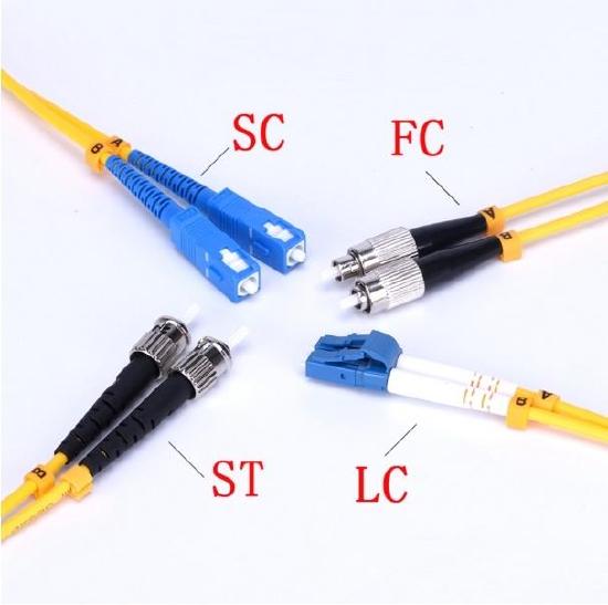
Optical fiber connectors
- Swapped optic cables
- While using fiber, most of the connection is done via a patch panel. Human error can occur at the time when the optic cables are plugged into the patch panel. Depending on the type of connector in the patch panel, (ST, SC, FC, or LC) the user will need to separate the cable and it may get swapped. This will cause the two wavelengths to collide and not transmit to the receiver LC connector.
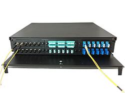
Fiber Optic Patch Panel
- Bent cable
- The SFPs are transmitting light. The fiber cables are designed to bounce the light between the borders of the cable. Therefore, if the cable is bent, the light will not pass.
Example of a bent cable
- Dirty Fiber Optic Connectors
- Traditional fiber optic core diameters are approximately 9 microns. Accumulated dust, even at the microscopic level, can create severe problems.
- Dust on the cable face or in the SFP optic transmitter/receiver may prevent the physical glass-to-glass contact required for proper signal transmission.
- Dirty fiber that blocks the fiber core generates strong back reflections and may impact attenuation (packet loss).
- Refer to the fiber manufacturer's documentation regarding the maximum bend radius