
Automatic Frequency Coordination
Overview:

Wi-Fi 6E introduces a new 6 GHz radio band for wireless communication. The FCC and ISED have opened 1,200 MHz of this spectrum for unlicensed use. This section was previously reserved for licensed services like Fixed Satellite Services, Satellite Service, Television and Broadcast Services, and Microwave Point-to-Point links. Automatic Frequency Coordination (AFC) protects these licensed services from Wi-Fi interference by managing spectrum sharing with existing users. Wi-Fi 6E access points must operate at either Standard Power or Low Power to comply with FCC and ISED rules.
Scenarios where AFC is required
- Indoor AP (Internal antenna) operation at Standard Power in 6 GHz
- Outdoor/ External antenna AP operation in 6 GHz
Lower Power V.S. Standard Power
Low Power
The Access Points in this device class can operate strictly indoors and must be equipped with only internal antennas. These communication regulatory bodies define the power level by a Power Spectral Density of 5 dBm/MHz. This allows APs to transmit at 18 dBm for a 20 MHz channel, 21 dBm for 40 MHz channel, 24 dBm for 80 MHz and 27 for 160 MHz channel. These APs can operate in the entire 1200 MHz of spectrum with a max EIRP of 30 dBm.
Standard Power
The access points in this device class can operate indoors or outdoors with an internal or external antenna with a Power Spectral Density at 23 dBm/MHz and a max EIRP of 36 dBm. Since these APs operate at a higher level, they can potentially interfere with the licensed 6 Ghz services operating within the spectrum. As a result, they are required to operate under the control of Automatic Frequency Coordination provider. the AFC provider serves as an independent central entity that allocates the channel and power levels based on the geolocation of the access points.
| Bandwidth | PSD max for LPI | PSD max for SP | EIRP max for LPI | EIRP max for SP |
|---|---|---|---|---|
| 20 MHz | 5 dBm/MHz | 23 dBm/MHz | 18 dBm | 36 dBm |
| 40 MHz | 5 dBm/MHz | 23 dBm/MHz | 21 dBm | 36 dBm |
| 80 MHz | 5 dBm/MHz | 23 dBm/MHz | 24 dBm | 36 dBm |
| 160 MHz | 5 dBm/MHz | 23 dBm/MHz | 27 dBm | 36 dBm |
Client Devices
As per the FCC and ISED regulations, the client devices must operate 6 dB lower than the power level of the AP to which it's associated.
Spectral density and Max EIRP values will vary based on regional regulatory requirements. Cisco Wireless APs will operate within the defined rules of the region to remain compliant.
AFC Operation
Automated Frequency Coordination System is a cloud-based operator (Example: Federated Wireless, Open AFC) that has access to regulatory domain specific 6 GHz, incumbent database, which stores geolocation coordinates and power of these licensed wireless services operating in the 6 GHz spectrum. In order to avoid interference the access point must present its geolocation coordinates to the AFC provider when powering on and before powering on the 6 GHz radio.
For cloud-based deployments, dashboard will serve as a proxy to the AP by requesting location information to pass to the AFC provider (Federated Wireless). Upon receiving the request, the AFC provider will query its database to see if there is an overlap of a licensed 6 GHz service in that geolocation. Based on its computed results, the AFC will send a response to the Dashboard on the channels and the power levels the AP can operate at.
AutoRF in Dashboard will then use this information to set the correct transmit power for channels for the AP. Dashboard administrators can also choose channels with knowledge of what power limits the channels have been provided by AFC. For every access point transmitting in the 6 GHz band at Standard power will need to have its AFC data refreshed once a day (every 24 hours) to stay in compliance.

Indoor access points that fail to renew their AFC status must decrease the TX power of their 6 GHz radio to operate at Indoor Low Power levels. Regulation on 6 GHz Wi-Fi allows indoor devices to operate in the full 6 GHz band (at ‘Indoor Low Power’ or ILP) without an active AFC status.
Outdoor access points that fail to renew their AFC status must shut down the 6 GHz radio. Per regulation, outdoor 6E APs can on the 6 GHz band at Standard Power and only under U-NII-5 and U-NII-7 bands.
AP Geolocation
As per regulation, APs operating at Standard Power must automatically obtain geolocation coordinates using an external or internal GPS module. To automatically obtain the geolocation of an access point, Cisco Wireless has developed the CW-ACC-GPS1. A GPS module that attaches to the USB port of select MR and CW model access points. Once installed, position the access point on the floor of a building near a window with a clear line of sight to the sky. The GPS module will then be able to acquire a satellite signal and share the AP's location with dashboard.
The mounting height of the AP is a necessary parameter, this measurement does not have to be auto-generated and can be manually entered in dashboard with a given range of uncertainty.
Geolocation Propagation
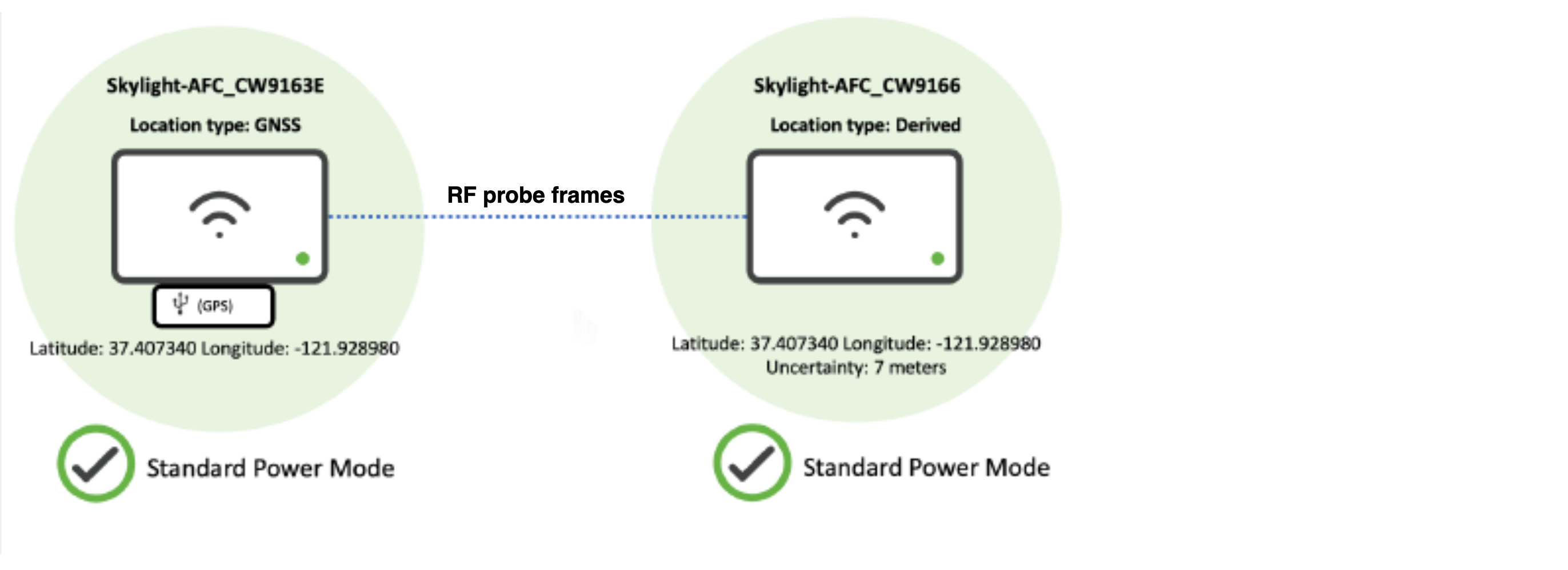
Access points enabled for Standard Power do not need an embedded or USB-attached GPS module. If at least one nearby access point has a valid GPS signal, other neighboring access points can leverage the same GPS coordinates with a relative measure of uncertainty. This process is known as geolocation propagation and can be accomplished either through wired proximity on the same layer 2 switch stack or share RF neighborship up to a calculated distance of up to 200 meters from an AP with a valid GPS signal.
In the two scenarios below, a location algorithm determines the relative position of the access point with a derived GPS location to the access point with a GPS module reporting GPS coordinates to dashboard (anchor AP).
Neighboring AP is able to see an anchor AP as its neighbor and can hear beacon frames on any band/ radio.

Neighboring AP is connected to the same dashboard-managed switch or switch stack as an anchor AP with the GPS module.
Firmware Requirements
- US AFC Support: MR 30.7 +
- Canada AFC Support: MR 32.1.x +
Feature Matrix
|
Country |
Regulatory Body |
Supported Bands |
Power Levels |
Supported Release |
Supported AP Models |
|
United States (US) |
FCC |
UNII-5, UNII-7 |
PSD 23dBm/MHz EIRP 36dBm |
R30.7 onwards |
|
|
R31.x |
|
||||
|
Canada (CA) |
ISED |
UNII-5, UNII-6, and UNII-7 |
PSD 23dBm/MHz EIRP 36dBm |
R32.1 + |
|
Compatible AP Models
Wi-Fi 6E indoor access points
- MR57
- CW9162
- CW9164
- CW9166I
- CW9166D1
Wi-Fi 6E outdoor access points
- CW9163E
Wi-Fi 7 indoor access points
- CW9172I
- CW9172H
- CW9176I
- CW9176D1
- CW9178I
Wi-Fi 7 indoor access points
- CW9179F
The CW9163E, CW9176I, CW9176D1, CW9178I, CW9179F come equipped with an internal GPS module to be auto-located by dashboard.
CW-ACC-GPS1 Module
-
Compatible with AP models with built-in USB port, i.e. MR57, CW9162, CW9164, CW9166I
-
TCP Port Number 443 has to be open in the corporate firewall.
-
Access Points (at least 1 or 2) need to be mounted where they can obtain satellite signals (e.g., near a window).
CW-ACC-GPS1 is the only external GPS module supported for AFC enablement. Please reach out to your Cisco or partner account team for procurement.

Installation
-
Insert the GPS module into the USB port of the access point.
-
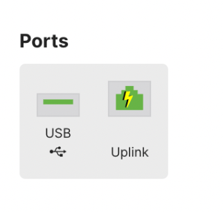
The USB port is configurable from the Wireless > Configure > Port Profiles page. For example the MR57, CW9166/64/62 will have USB labeled as a configurable port.
-
Create a new port profile.
-
Enable USB port.
-
Assign the profile to AP.
-
Ensure the USB port is receiving power via dashboard.


 .
.
GNSS Antenna Installation
PID: CW-ANT-GPS1-M-00
APs installed away from a clear line of sight to the sky can extend satellite reception by 10 meters using the CW-ANT-GPS1-M-00 GNSS antenna.
- Insert the CW-ACC-GPS1 GPS module into the USB port of the access point.
- Remove the covering on the GPS module to reveal the GNSS port and insert the antenna.
- Determine the desired placement of the antenna bracket on a window pane that allows for a clear line of sight to the sky.
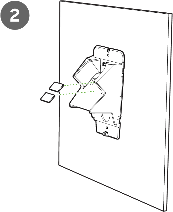
- Apply the adhesive strips to the top and bottom portions of the bracket.
- Apply adhesive strips to the inside of the bracket to secure the antenna.
- Insert the antenna into the bracket and ensure proper adhesion to the strips.
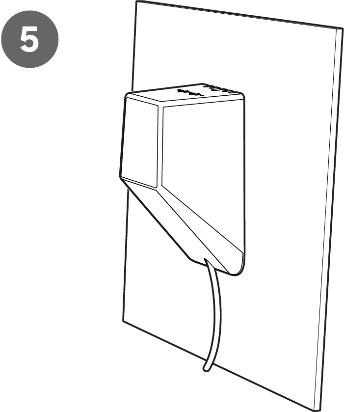
- Clip the outer casing to the bracket and thread the cabling through the case opening.
Indoor Deployment


Outdoor Deployment
Outdoor GPS antenna deployments require a 180-degree rotation of the mounting bracket to allow the antenna to be positioned toward the sky.


Mounting the AP

-
Ensure the AP is mounted where the GPS module can obtain the satellite signal (e.g., near a window).
AFC Configuration

-
Navigate to Wireless > Configure > Radio settings > RF profiles.
-
Edit the default or custom RF profile the APs are assigned to in the network.
-
Under the 6 GHz radio settings, enable Standard Power service.

-
Click Set height for APs to manually set the height parameter of APs in the network.

If APs are installed at the same height, you can bulk assign by using filters for AP tags or floor plans. Alternatively, you can select APs individually and set height parameters.
-
Click on Set height.

-
Enter the approximate height from the ground level to the AP’s mounting location.
-
Select a height accuracy range from the drop-down menu.
The height of the AP should be from the ground level to the AP and not the floor on which the AP is located.
Federal communication guidelines defines this perameter as "antenna height above ground."
Having a smaller height accuracy range leads to a higher accuracy of power limits reported by the AFC provider.
Height is required to be reported accurately for AFC-enabled APs to remain in compliance.
If an external GPS antenna is used to achieve satellite reception for the AP, the cable length will default to 10 meters. If no external antenna is detected, the cable length will default to 0 meters.
-
Save the configuration

-
Click Done once the height is set for all APs assigned to the RF profile.
WiFi 6E requires the clients to support WPA3 as a mandatory mode of encryption. WPA2-WPA3 transition mode is not supported in the 6 GHz frequency. For further information on WPA3 encryption and configuration refer to this document.
After enabling Standard Power within the RF profile, assigned access points will reboot to enable the 6 GHz radio. It is recommended to enable AFC during a planned maintenance window.
Verify AFC Status

-
Navigate to the Access Point list, and select an AP that is now enabled for AFC.
-
From the AP’s overview page, select the AFC tab.
AFC Status

The AFC overview page shows the current AFC status of an AP. A status of active means a successful request to the AFC provider along with the associated response. The AFC status page includes the target expiration time at which the current AFC response expires. Per regulation, every AP operating in 6 GHz, AFC status needs to be refreshed once a day (every 24 hours).
Power Mode

After enabling AFC and verifying that Standard Power (SP) operation is permitted on specific 6 GHz channels in the access point's geographic location, the AP will switch its 6 GHz radios to Standard Power (SP) mode. This power mode allows for an Equivalent isotropic radiated power (EIRP) of up to 36 dBm or a max Power Spectral Density (PSD) of 23 dBm/MHz for the regulatory domain on an eligible channel.
AFC Defined AP Location

The Location type specifies how the AP’s geographical location is determined.
If an AP has a GPS module either internally or externally and it has acquired a signal from a satellite, the Location type will indicate "GNSS" (Global Navigation Satellite System), along with the latitude and longitude coordinates of the AP. This indicates that the GPS module has recorded the positioning of the AP locally,
Global Navigation Satellite System (GNSS) refers to a constellation of satellites providing signals from space that transmit positioning and timing data to GNSS receivers. The receivers then use this data to determine location.
If the location type is reported as "Derived" it means that the location was not obtained locally via a GPS module, but rather through wired or wireless geolocation propagation with a neighboring AP.
If the Location type is empty, AFC operation is not allowed or otherwise impossible as neither GPS nor wired/wireless propagation was successful or invoked (i.e., if AFC is disabled, no valid GPS signal, the USB port is down, etc.).
After the AP powers up (or) the USB port registers as enabled, wait 10 minutes for the AP to obtain a GPS signal. If the GPS module can get a satellite signal, the location will be automatically populated with the source as “GNSS".

APs that have their location "Derived" share the same geographical coordinates as the neighbor AP with a satellite signal. Dashboard provides an estimate of the distance between the APs with a level of uncertainty. This uncertainty level is passed to the AFC provider, which regulates a lower power allowance for the derived AP to operate.

Channel Availability

The channel availability is displayed in a chart view showing the power levels assigned by the AFC provider across the 6 GHz spectrum based on the AP's location and installation height. In Dashboard, AutoRF uses these power limits shared by the AFC provider to set the appropriate transmit power of the AP. The power table and channel assignment for the 6 GHz radio needs to be updated dynamically every 24 hours to comply. This process ensures that APs broadcasting in 6 GHz at Standard Power do not interfere with licensed 6 Ghz services (i.e. microwave P2P links, satellite links, etc.).
Transmit Power Levels
Please note TX power levels listed within the AP details page are the base transmit power levels of the AP’s radios and do not include the TX gain from attached antennas.

AFC Refresh
Dashboard administrators can refresh the AFC status of selected APs. This tool will queue the AP to issue a new available spectrum inquiry request to the AFC service provider (i.e., Federated Wireless). Within a few moments of selecting this option, the current "afc_expires_at" and "afc_updated_at" timers should be refreshed and updated once an Available Spectrum Inquiry Response has been received.

-
Navigate Wireless > Configuration > Radio Settings.
-
Select the checkbox next to one or more AFC-capable APs in the 6 GHz radio list.

-
Click the Refresh AFC at the top of the page.
The specified power limits or channel constraints may or may not have changed based on the results of the new AFC response. Hence, SP mode, transmit power, and/or channel assignment for the 6 GHz radio is also subject to change.
Monitoring & Troubleshooting

The AP does not have an auto-generated location
When you see This AP does not have an auto-generated location alert under AFC defined AP location, that means that the Dashboard failed to receive location information (from either GNSS or propagation). Ensure the AP has clear line of sight to the sky, you may need to install the AP close to a window. You can review the AP Geolocation section for more details.
AFC enabled but not configured properly
The following are some considerations and steps to bring up and validate that GPS is working on a given access point:
-
Confirm a secure connection of CW-ACC-GPS1 module to the USB port of the access point's USB port.
All Cisco Wireless indoor, 6 GHz capable access points require an external GPS module to operate at Standard Power.
Outdoor access point models like the CW9163E have an internal module for GPS.
-
Reboot the access point, and ensure that the AP is fully powered (e.g. 802.3at / PoE).
-
Ensure that AFC is enabled on the RF Profile associated with the AP in question and that the AP height and uncertainty values are accurately configured in Dashboard.
-
Verify that the AP recognizes the GPS module for use with AFC:
AFC not supported:
- Firmware does not support SP
- AP is not SP capable/6GHz capable
- Network is not set to the correct regulatory domain
- For APs with flex 5/6 radio, flex radio set to 5 GHz (no 6 GHz radios)
For the above reasons, the AFC tab on the AP details page will not show up
AP Neighborship
Stronger RF neighborship leads to more consistent results. Weak neighborship near the noise floor increases the risk of gaps. These deployments are also more likely to experience performance issues and problems with geolocation propagation.
Target an RF neighborship of an RSSI of at least -75 dBm or better on any band (i.e. 2.4 GHz or 5 GHz or 6 GHz) and an SNR of 15-20 or better for optimal and consistent results. Results will vary from one wireless environment to the next.
AFC Response Event Log

Admins can verify a response was received from AFC from the Event Logs.
-
AFC response received- Provides details on the historical list of AFC responses for a specific access point, including the recent update to an AP’s AFC status.
-
Each AFC response event log contains the power limits passed from the AFC provider to the AP in a JSON file. This configuration file defines the approved channels and transmit power levels allowed by the AFC provider (Federated Wireless) for the AP to operate.
AFC Status
.png?revision=2)
If the connection status shows inactive, it may be due to:
- AP height is not being configured. To configure it, review step 4 of the AFC Configuration section.
- No AFC response (highlighted in red)
An inactive connection status highlighted in red means an AFC request has been sent out but there is no AFC response. This is due to a connection issue between the Dashboard and the AFC system. This usually occurs when the AFC services are down, and in such cases, it is advised to wait for the services to resume automatically.
AFC API Endpoints:
|
Configuration |
API Endpoint |
Details |
|---|---|---|
|
AFC Enable/Disable |
PUT /networks/{networkId}/wireless/rfProfiles/{rfProfileId} |
Enable or Disable AFC at RF profile level. APs are then assigned to the RF profile |
|
Height |
PUT /devices/{serial}/wireless/radio/afc/positioning |
Configure height at AP Level |
|
Height Uncertainty |
PUT /devices/{serial}/wireless/radio/afc/positioning |
Configure height uncertainty at AP Level |
|
Cable Length |
PUT /devices/{serial}/wireless/radio/afc/positioning |
Configure cable length at AP Level |
|
AFC Refresh |
POST /devices/{serial}/wireless/radio/afc/refresh |
Queues the AP for an AFC refresh to override the 22 hour refresh |
|
Monitoring |
API Endpoint |
|
|
AFC Status |
GET /devices/{serial}/wireless/radio/afc/powerLimits GET /organizations/{organizationId}/wireless/radio/afc/powerLimits/byDevice |
Get status of most recent AFC response for device or for whole organization (can filter with list of network IDs) |
|
Power Mode |
GET /devices/{serial}/wireless/radio/status |
Get radio’s power mode (SP or LPI or Off) per AP |
|
Last Response |
GET /devices/{serial}/wireless/radio/afc/powerLimits GET /organizations/{organizationId}/wireless/radio/afc/powerLimits/byDevice |
Get info on most recent AFC response (expiration time, power limits, etc.) by AP or by organization (can filter with list of network IDs) |