
High Density Wi-Fi Deployments
High-density Wi-Fi is a design strategy for large deployments to provide pervasive connectivity to clients when a high number of clients are expected to connect to Access Points within a small space. A location can be classified as high density if more than 30 clients are connecting to an AP. To better support high-density wireless, Cisco Meraki access points are built with a dedicated radio for RF spectrum monitoring allowing the MR to handle the high-density environments. Unless additional sensors or air monitors are added, access points without this dedicated radio have to use proprietary methods for opportunistic scans to better gauge the RF environment and may result in suboptimal performance.
Large campuses with multiple floors, distributed buildings, office spaces, and large event spaces are considered high density due to the number of access points and devices connecting. More extreme examples of high-density environments include sports stadiums, university auditoriums, casinos, event centers, and theaters.
As Wi-Fi continues to become ubiquitous, there is an increasing number of devices consuming an increasing amount of bandwidth. The increased need for pervasive connectivity can put additional strain on wireless deployments. Adapting to these changing needs will not always require more access points to support greater client density. As the needs for wireless connectivity have changed over time, the IEEE 802.11 wireless LAN standards have changed to adapt to greater density, from the earliest 802.11a and 802.11b standards in 1999 to the most recent 802.11ac standard, introduced in 2013 and the new 802.11ax standard currently being developed.
Planning
In the recent past, the process to design a Wi-Fi network centered around a physical site survey to determine the fewest number of access points that would provide sufficient coverage. By evaluating survey results against a predefined minimum acceptable signal strength, the design would be considered a success. While this methodology works well to design for coverage, it does not take into account requirements based on the number of clients, their capabilities, and their applications' bandwidth needs.
Understanding the requirements for the high density design is the first step and helps ensure a successful design. This planning helps reduce the need for further site surveys after installation and for the need to deploy additional access points over time. It is recommended to have the following details before moving onto the next steps in the design process:
-
Type of applications expected on the network
-
Supported technologies (802.11 a/b/g/n/ac/ax)
-
Type of clients to be supported (Number of spatial streams, technologies, etc.)
-
Areas to be covered
-
Expected number of simultaneous devices in each area
-
Aesthetic requirements (if any)
-
Cabling constraints (if any)
-
Power constraints (It’s best to have PoE+ capable infrastructure to support high performance APs)
Capacity Planning
Once the above mentioned details are available, capacity planning can then be broken down into the following phases:
-
Estimate Aggregate Application Throughput
-
Estimate Device Throughput
-
Estimate Number of APs
Calculating the number of access points necessary to meet a site's bandwidth needs is the recommended way to start a design for any high density wireless network.
Estimate Aggregate Application Throughput
Usually there is a primary application that is driving the need for connectivity. Understanding the throughput requirements for this application and any other activities on the network will provide will provide a per-user bandwidth goal. This required per-user bandwidth will be used to drive further design decisions. Throughput requirements for some popular applications is as given below:
|
Application |
Throughput |
|
Web Browsing |
500 kbps (kilobits) |
|
VoIP |
16 - 320 kbps |
|
Video conferencing |
1.5 Mbps |
|
Streaming - Audio |
128 - 320 kbps |
|
Streaming - Video |
768 kbps |
|
Streaming - Video HD |
768 kbps - 8mbps |
|
Streaming - 4K |
8 mbps - 20mbps |
Note: In all cases, it is highly advisable to test the target application and validate its actual bandwidth requirements. It is also important to validate applications on a representative sample of the devices that are to be supported in the WLAN. Additionally, not all browsers and operating systems enjoy the same efficiencies, and an application that runs fine in 100 kilobits per second (Kbps) on a Windows laptop with Microsoft Internet Explorer or Firefox, may require more bandwidth when being viewed on a smartphone or tablet with an embedded browser and operating system
Once the required bandwidth throughput per connection and application is known, this number can be used to determine the aggregate bandwidth required in the WLAN coverage area. It is recommended to have an aggregate throughput for different areas such as classrooms, lobby, auditorium, etc. as the requirements for these areas might be different.
As an example, we will design a high-density Wi-Fi network to support HD video streaming that requires 3 Mbps of throughput. Based on the capacity of the auditorium, there may be up to 600 users watching the HD video stream. The aggregate application throughput can be calculated using the below given formula:
(Application Throughput) x (Number of concurrent Users) = Aggregate Application Throughput
3 Mbps x 600 users = 1800 Mbps
Note that 1.8 Gbps exceeds the bandwidth offerings of almost all internet service providers. The total application bandwidth we are estimating is a theoretical demand upper bound, which will be used in subsequent calculations.
Estimate Device Throughput
While Meraki APs support the latest technologies and can support maximum data rates defined as per the standards, average device throughput available often dictated by the other factors such as client capabilities, simultaneous clients per AP, technologies to be supported, bandwidth, etc.
Client capabilities have a significant impact on throughput as a client supporting only legacy rates will have lower throughput as compared to a client supporting newer technologies. Additionally, bands supported by the client may also have some impact on the throughput. Meraki APs have band steering feature that can be enabled to steer dual band clients to 5 GHz.
Note: A client supporting only 2.4 GHz might have lower throughput as compared to a dual band client since higher noise level is expected on the 2.4GHz as compared to 5 GHz and the client might negotiate lower data rate on 2.4GHz.
In certain cases, having dedicated SSID for each band is also recommended to better manage client distribution across bands and also removes the possibility of any compatibility issues that may arise.
To assess client throughput requirements, survey client devices and determine their wireless capabilities. It is important to identify the supported wireless bands (2.4 GHz vs 5 GHz), supported wireless standards (802.11a/b/g/n/ac), and the number of spatial streams each device supports. Since it isn’t always possible to find the supported data rates of a client device through its documentation, the Client details page on Dashboard can be used as an easy way to determine capabilities.
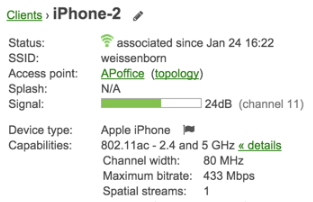
Example Client details listing
Wi-Fi is based on CSMA/CA and is half-duplex. That means only one device can talk at a time while the other devices connected to the same AP wait to for their turn to access the channel. Hence, simultaneous client count also has an impact on AP throughput as the available spectrum is divided among all clients connected to the AP. While Meraki has client balancing feature to ensure clients are evenly distributed across AP in an area an expected client count per AP should be known for capacity planning.
Note: In order to ensure quality of experience it is recommended to have around 25 clients per radio or 50 clients per AP in high-density deployments.
Starting 802.11n, channel bonding is available to increase throughput available to clients but as a result of channel bonding the number of unique available channels for APs also reduces. Due to the reduced channel availability, co-channel interference can increase for bigger deployments as channel reuse is impacted causing a negative impact on overall throughput.
Note:In a high-density environment, a channel width of 20 MHz is a common recommendation to reduce the number of access points using the same channel.
Client devices don’t always support the fastest data rates. Device vendors have different implementations of the 802.11ac standard. To increase battery life and reduce size, most smartphone and tablets are often designed with one (most common) or two (most new devices) Wi-Fi antennas inside. This design has led to slower speeds on mobile devices by limiting all of these devices to a lower stream than supported by the standard. In the chart below, you can see the maximum data rates for single stream (433 Mbps), two stream (866 Mbps), and three stream (1300 Mbps). No devices on the market today support 4 spatial streams or wider 160 MHz channels, but these are often advertised as optional "Wave 2" features of the 802.11ac standard.
|
Streams |
20 MHz Channel Width |
40 MHz Channel Width |
80 MHz Channel Width |
|
1 Stream |
87 Mbps |
200 Mbps |
433 Mbps |
|
2 Streams |
173 Mbps |
400Mbps |
866 Mbps |
|
3 Streams |
289 Mbps |
600 Mbps |
1300 Mbps |
The actual device throughput is what matters to the end user, and this differs from the data rates. Data rates represent the rate at which data packets will be carried over the medium. Packets contain a certain amount of overhead that is required to address and control the packets. The actual throughput is payload data without the overhead. Based on the advertised data rate, next estimate the wireless throughput capability of the client devices. A common estimate of a device's actual throughput is about half of the data rate as advertised by its manufacturer. As noted above, it is important to also reduce this value to the data rate for a 20 MHz channel width. Below are the most common data rates and the estimated device throughput (half of the advertised rate). Given the multiple factors affecting performance it is a good practice to reduce the throughput further by 30%
|
Protocol |
Data rate (Mbps) |
Estimated Throughput (1/2 advertised rate) |
Throughput w/Overhead |
|---|---|---|---|
|
802.11a or 802.11g |
54 Mbps |
27 Mbps |
~19 Mbps |
|
1 stream 802.11n |
72 Mbps |
36 Mbps |
~25 Mbps |
|
2 stream 802.11n |
144 Mbps |
72 Mbps |
~50 Mbps |
|
3 stream 802.11n |
216 Mbps |
108 Mbps |
~76 Mbps |
|
1 stream 802.11ac |
87 Mbps |
44 Mbps |
~31 Mbps |
|
2 stream 802.11ac |
173 Mbps |
87 Mbps |
~61 Mbps |
|
3 stream 802.11ac |
289 Mbps |
145 Mbps |
~102 Mbps |
|
1 stream 802.11ax |
143 Mbps |
72 Mbps |
~50 Mbps |
|
2 stream 802.11ax |
287 Mbps |
144 Mbps |
~101 Mbps |
|
3 stream 802.11ax |
430 Mbps |
215 Mbps |
~151 Mbps |
Estimate the Number of APs
It's important to document and review the requirements and assumptions and confirm they are reasonable. Changing one assumption will significantly impact the number of access points and the costs. If you assumed just 1.5 Mbps for HD video chat (as recommended by Microsoft Skype and Cisco Spark) you would need half the number of access points. If you assumed 5 Mbps was required for HD video streaming (as recommended by Netflix) you would need more access points. If you were designing to support 600 1 stream devices instead of 600 3 stream laptops, you would need roughly 3 times the number of access points. For this example, we now have the following requirements and assumptions:
-
Video streaming requires 3 Mbps for HD quality video
-
There will be 600 concurrent users streaming video to their laptop
-
Every user has an Apple MacBook Pro or similar
-
All laptops support 802.11ac and are capable of 3 spatial streams
-
The network will be configured to use 20 MHz channels
-
Each access point can provide up to 101 Mbps of wireless throughput
We can now calculate roughly how many APs are needed to satisfy the application capacity. Round to the nearest whole number.
Number of Access Points based on throughput = (Aggregate Application Throughput) / (Device Throughput)
Number of Access Points based on throughput = 1800 Mbps/101Mbps = ~18 APs
In addition to the number of APs based on throughput, it is also important to calculate the number of APs based on clients count. To determine number of APs, first step is to estimate the clients per band. With newer technologies, more devices now support dual band operation and hence using proprietary implementation noted above devices can be steered to 5 GHz.
Note: A common design strategy is to do a 30/70 split between 2.4 GHz and 5 GHz
For this example, we now have the following requirements and assumptions:
-
There will be 600 concurrent users streaming video to their laptop
-
Concurrent 2.4 GHz clients = 600 * 0.3 = 180
-
Concurrent 5 GHz clients = 600 * 0.7 = 420
We can now calculate roughly how many APs are needed to satisfy the client count. Round to the nearest whole number.
Number of Access Points based on client count = (Concurrent 5 GHz clients) / 25
Number of Access Points based on client count = 420 / 25 = ~17 APs
Now the Number of APs required can be calculated by using the higher of the two AP counts.
Number of Access Points = Max (Number of Access Points based on throughput, Number of Access Points based on client count)
Number of Access Points = Max (18,17) = 18 APs
Site Survey and Design
Performing an active wireless site survey is a critical component of successfully deploying a high-density wireless network and helps to evaluate the RF propagation in the actual physical environment. The active site survey also gives you the ability to actively transmit data and get data rate coverage in addition to the range.
In addition to verifying the RF propagation in the actual environment, it is also recommended to have a spectrum analysis done as part of the site survey in order to locate any potential sources of RF interference and take steps to remediate them. Site surveys and spectrum analysis are typically performed using professional grade toolkits such as Ekahau Site Survey or Fluke Networks Airmagnet. Ensure a minimum of 25 dB SNR throughout the desired coverage area. Remember to survey for adequate coverage on 5GHz channels, not just 2.4 GHz, to ensure there are no coverage holes or gaps. Depending on how big the space is and the number of access points deployed, there may be a need to selectively turn off some of the 2.4GHz radios on some of the access points to avoid excessive co-channel interference between all the access points.
Note: It is recommended to have complete coverage for both bands.
Note: Read our guide on Conducting Site Surveys with MR Access Points for more help on conducting an RF site survey.
Mounting Access Points
The two main strategies for mounting Cisco Meraki access points are ceiling mounted and wall mounted. Each mounting solution has advantages.
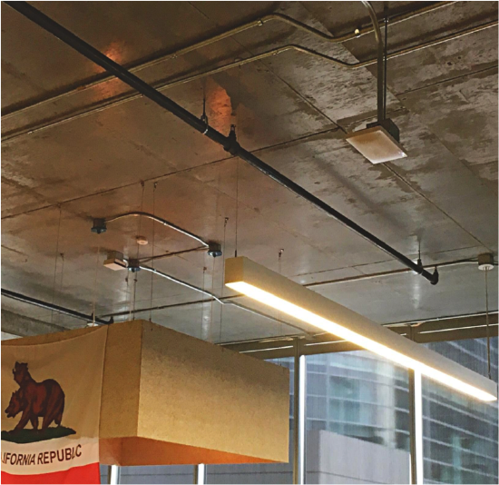
Ceiling mounted MR, Cisco San Francisco
Ceiling mounted access points are placed on a ceiling tile, T-bar, roof, or conduit extending down from the roof. This brings advantages such as a clear line-of-sight to the user devices below and flexibility in where to place the access point. Access points can be easily placed with even spacing in a grid and at the intersection of hallways. The disadvantage is the ceiling height and the height of the access point could negatively impact the coverage and capacity.
-
If access points have to be installed below 8 feet (~3 meters), indoor access points with integrated omni antennas or external dipole/can omni antennas are recommended.
-
If access points have to be installed between 8 - 25 feet (3 - 8 meters), indoor access points with external downtilt omni antennas are recommended.
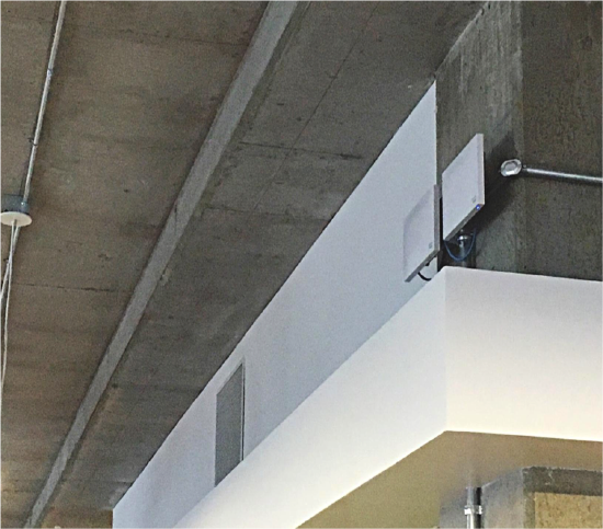
Wall mounted MRs, Cisco San Francisco
When ceiling heights are too high (25+ feet) or not feasible to mount access points (hard ceiling), a wall mounted design is recommended. The access points are mounted on drywall, concrete or even metal on the exterior and interior walls of the environment. Access points are typically deployed 10-15 feet (3-5 meters) above the floor facing away from the wall. Remember to install with the LED facing down to remain visible while standing on the floor. Designing a network with wall mounted omnidirectional APs should be done carefully and should be done only if using directional antennas is not an option.
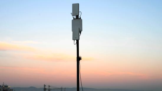
Pole mounted MR66 with Sector antennas, Cisco San Francisco
Directional Antennas
If there is no mounting solution to install the access point below 26 feet (8 meters), or where ceilings are replaced by the stars and the sky (outdoors), or if directional coverage is needed it is recommend to use directional antennas. When selecting a directional antenna, you should compare the horizontal/vertical beam-width and gain of the antenna.
When using directional antennas on a ceiling mounted access point, direct the antenna pointing straight down. When using directional antennas on a wall mounted access point, tilt the antenna at an angle to the ground. Further tilting a wall mounted antenna to pointing straight down will limit its range.
Cisco Meraki offers 6 types of indoor-rated external antennas (available for MR42E and MR53E):
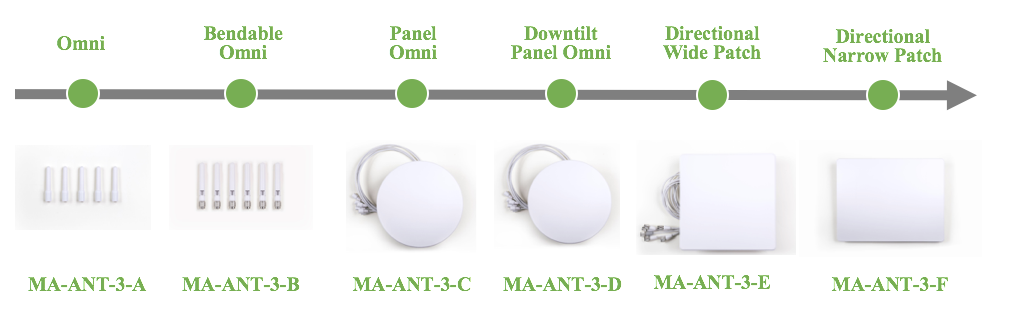
C/D/E/F series antennas will be automatically detected by the AP. Once an antenna is detected by the AP it cannot be changed in dashboard until the antenna is removed and AP is rebooted.
Cisco Meraki offers 4 types of outdoor external antennas and supports 5 types of outdoor antennas. Cisco Meraki has certified the antennas for use with the Meraki MR84, MR74, MR72, MR66, and MR62 access points. AIR-ANT2514-P4M can only be used with MR84:
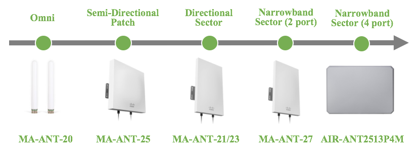
Using 3rd party antennas with gain higher than 11 dBi on 2.4 GHz or 13 dBi on 5 GHz may violate regulations in some countries. Meraki certifies only Meraki antennas.
Access Point Placement
Once the number of access points has been established, the physical placement of the AP’s can then take place. A site survey should be performed not only to ensure adequate signal coverage in all areas but to additionally assure proper spacing of APs onto the floorplan with minimal co-channel interference and proper cell overlap. It’s very important to consider the RF environment and construction materials used for AP placement.
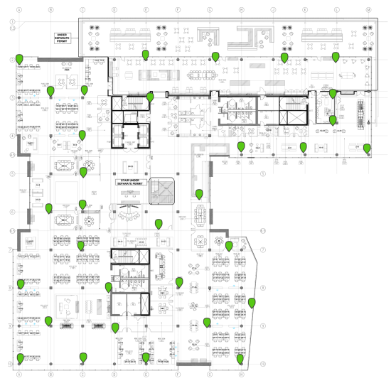
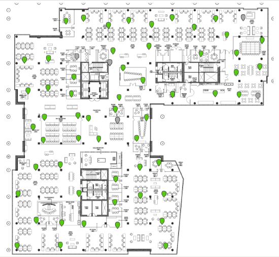
Review the designs below from the Cisco Meraki San Francisco office. The 4th Floor was constructed to support Cisco's sales team, customer briefings, and a cafe. In contrast, the 3rd floor was constructed to support Cisco's 24x7 technical support, our small IT department, and Cisco's Collaboration group with applications such as Telepresence and Cisco Spark HD video chat. The density of the 3rd floor is double that of the 4th floor.
High density with 30 access points, Cisco San Francisco, 4th Floor
Ultra High density with 60 access points, Cisco San Francisco, 3rd Floor
SSID Configuration
Making the changes described in this section will provide a significant improvement in overall throughput by following the best practices for configuring SSIDs, IP assignment, Radio Settings, and traffic shaping rules.
Number of SSIDs
The maximum recommended number of SSIDs is 3, and in a high-density environment, this recommendation becomes a requirement. If needed, the number of SSIDs can be increased to 5 but should be done only when necessary. Using more than 5 SSIDs creates substantial airtime overhead from management frames: consuming 20% or more of the bandwidth available and limiting the maximum throughput to less than 80% of the planned capacity. Create a separate SSID for each type of authentication required (Splash, PSK, EAP) and consolidate any SSIDs that use the same type authentication.
Adding several SSIDs has a negative impact on capacity and performance. See the article Multi-SSID Deployment Considerations for more detail.
Enable Bridge Mode
Bridge mode is recommended to improve roaming for voice over IP clients with seamless Layer 2 roaming. In bridge mode, the Meraki APs act as bridges, allowing wireless clients to obtain their IP addresses from an upstream DHCP server. Bridge mode works well in most circumstances, provides seamless roaming with the fastest transitions. When using Bridge mode, all APs in the intended area (usually a floor or set of APs in an RF Profile) should support the same VLAN to allow devices to roam seamlessly between access points.
For seamless roaming in bridge mode, the wired network should be designed to provide a single wireless VLAN across a floor plan. If the network requires a user to roam between different subnets, using L3 roaming is recommended. Bridge mode will require a DHCP request when roaming between two subnets or VLANs. During this time, real-time video and voice calls will noticeably drop or pause, providing a degraded user experience.
NAT mode is not recommended for Voice over IP: With NAT mode enabled, devices will request a new DHCP IP address on each roam. Moving between APs in NAT mode will cause the connection to break when moving AP to AP. Applications requiring continuous traffic streams such as VoIP, VPN or media streams will be disrupted during roaming between APs.
Layer 3 Roaming
Distribute Layer 3 Roaming (D3LR) and MX as a Concentrator are no longer recommended solutions for large scale roaming.
Large wireless networks that require fast and seamles roaming across multiple AP VLANs and subnets will need a centralized wireless deployment with to enable application and session persistence while mobile clients roams at scale.
Within Meraki dashboard, Cisco Campus Gateway is the solution to centralize wireless traffic from Cisco cloud-managed access points and is a cloud-native solution built for large campus wireless deployments. The Campus Gateway tunnels SSID traffic from APs over Virtual eXtensible Local Area Network (VXLAN) to the Campus Gateway, which then bridges the traffic to the upstream network. A single Campus Gateway can support up to 5,000 access points and 50,000 clients with up to 100 Gbps of throughput, and a cluster of two Campus Gateway s doubles that to 200 Gbps.
Please refer to the Campus Gateway Deployment Guide.
Radio Settings & Auto RF
Cisco Meraki access points feature a third radio dedicated to continuously and automatically monitoring the surrounding RF environment to maximize Wi-Fi performance even in the highest density deployment. By measuring channel utilization, signal strength, throughput, signals from non-Meraki APs, and non-WiFi interference, Cisco Meraki APs automatically optimize the radio transmit power and selected operating channels of individual APs to maximize system-wide capacity.
Additionally, it is recommend to use RF profiles to better tune the wireless network to support the performance requirements. A separate RF profile should be created for each area that needs unique set of RF settings. The following details can be set in the RF Profiles:
Band Selection
If the client devices require 2.4 GHz, enable 'Dual-band with band steering' to enable client devices to use both 2.4 GHz channels and 5 GHz. Devices will be steered to use the 5 GHz band. For more details refer to the Band Steering Overview article. With a dual-band network, client devices will be steered by the network. If 2.4 GHz support is not needed, it is recommended to use “5 GHz band only”. Testing should be performed in all areas of the environment to ensure there are no coverage holes.

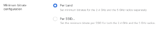
Set Minimum Bitrate
Using RF Profiles, minimum bit rate can be set on a per band or a per SSID basis. For high-density networks, it is recommended to use minimum bit rates per band. If legacy 802.11b devices need to be supported on the wireless network, 11 Mbps is recommended as the minimum bitrate on 2.4 GHz. Adjusting the bitrates can reduce the overhead on the wireless network and improve roaming performance. Increasing this value requires proper coverage and RF planning. An administrator can improve the performance of clients on the 2.4 GHz and 5 GHz band by disabling lower bitrates. Management frames will be sent out at the lowest selected rate. Clients must use either the lowest selected rate or a faster one. Selecting a Minimum bitrate of 12Mbps or greater will prevent 802.11b clients from joining and will increase the efficiency of the RF environment by sending broadcast frames at a higher bitrate.
Note: As per standards, 6 Mbps, 12 Mbps and 24 Mbps are the mandatory data rates. Cisco's San Francisco office uses 18 Mbps as the Minimum bitrate.
Auto Power Reduction
Every second the access point's radios samples the signal-to-noise (SNR) of neighboring access points. The SNR readings are compiled into neighbor reports which are sent to the Meraki Cloud for processing. The Cloud aggregates neighbor reports from each AP. Using the aggregated data, the Cloud can determine each AP's direct neighbors and how by much each AP should adjust its radio transmit power so coverage cells are optimized. For determining the changes in TX power the cloud tries to ensure that there are at least 3 heard by each in the area. The calculations are done every 20 minutes and once complete, the Cloud instructs each AP to decrease or increase the transmit power.TX power can be reduced by 1-3 dB per iteration and is increased in 1 dB iterations.
AutoRF tries to reduce the TX power uniformly for all APs within a network but in complex high density network it is necessary to limit the range and the values for the AP to use. To better support complex environments, minimum and maximum TX power settings can be configured in RF profiles.
Note: For 2.4 GHz, Auto Power reduction algorithm allows TX power to go down only up to 5 dBm. For 5 GHz, Auto Power reduction algorithm allows TX power to go down only up to 8 dBm. If lower TX power is needed, APs can be statically set to lower power.
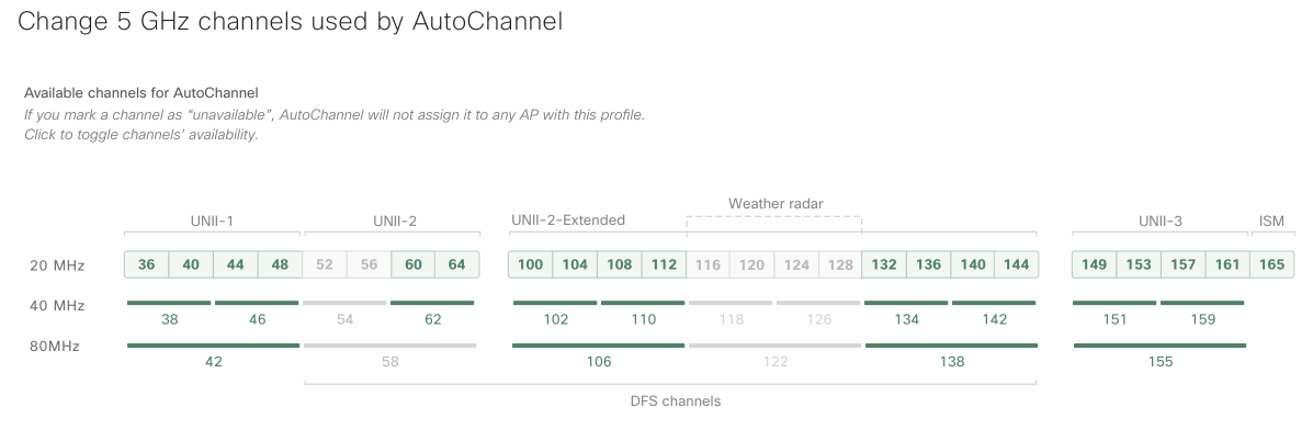
Auto Channel selection
Adding additional access points on the same channel with overlapping coverage does not increase capacity. To prevent access points nearby from sharing the same channel, Cisco Meraki access points automatically adjusts the channels of the radios to avoid RF interference (Both 802.11 and non-802.11) and develop a channel plan for the Wireless Network. Channels can be selectively assigned to be used with each RF profile. By using channels selectively, network administrators can control the co-channel interference more effectively.
Default Channel Width
-
In moving towards 40-Mhz or 80-Mhz channels, you are effectively halving (if selecting 40-MHz) or quartering (80-MHz) the number of non-overlapping 5GHz channels by doubling or quadrupling the channel width due to channel bonding. This, in turn, increases the distance at which access points must be placed if co-channel interference (CCI) and adjacent channel interference (ACI) are to be kept to a minimum.
-
While using 40-MHz or 80-Mhz channels might seem like an attractive way to increase overall throughput, one of the consequences is reduced spectral efficiency due to legacy (20-MHz only) clients not being able to take advantage of the wider channel width resulting in the idle spectrum on wider channels. Depending on the RF environment, even clients capable of 40 and 80 MHz may only use the 20 MHz base channel and is often observed in highly contentious RF environments.
-
Due to the mix of clients usually seen in high-density deployments (such as laptops, mobile phones, and tablets etc.) the capabilities of clients in such environments also vary (some will support 20-Mhz, some will support 40-MHz and some will support 80-Mhz channels). Due to this, it is better to have each client communicating at the lowest common channel width, giving each client equal access to the network. It is better to have 4 clients communication at 20-MHz with 4 access points, rather than 4 clients of mixed capability communicating with 1 access points at 80-MHz resulting in idle.
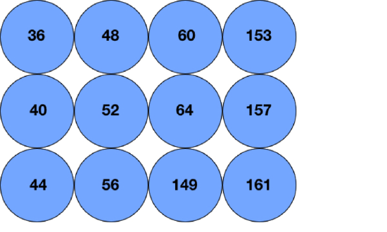
DFS Channels and Channel Reuse
For an example deployment with DFS channels enabled and channel reuse is not required, the below grid shows 12 access points with no channel reuse. As there are 19 channels in the US, when you reach 20 access points in the same space, the APs will need to reuse a channel.
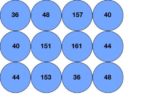
For a deployment example where DFS is disabled and channel reuse is required, the below diagram shows 4 channels being reused in the same space. When channel reuse cannot be avoided, the best practice is to separate the access points on the same channel as much as possible.
RX-SOP
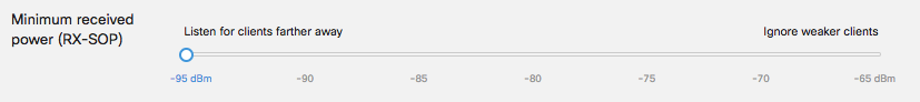
|
802.11 Band |
High Threshold |
Medium Threshold |
Low Threshold |
|
5 GHz |
-76 dBm |
-78 dBm |
-80 dBm |
|
2.4 GHz |
-79 dBm |
-82 dBm |
-85 dBm |
Note: RX-SOP is supported on 802.11 ac Wave 2 and 802.11 ax APs i.e. MR30H/33/42/52/53/74/84/42E/53E/45/55
Client Balancing
Roaming in High Density
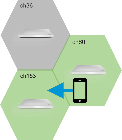
Client roaming between access points
Enable Fast Roaming
Cisco Meraki MR access points support a wide array of fast roaming technologies. For a high-density network, roaming will occur more often, and fast roaming is important to reduce the latency of applications while roaming between access points. All of these features are enabled by default, except for 802.11r.
- 802.11r (Fast BSS Transition) - 802.11r allows encryption keys to be stored on all of the APs in a network. This way, a client doesn't need to perform the full re-authentication process to a RADIUS server every time it roams to a new access point within the network. This feature can be enabled from the Configure > Access control page under Security > 802.11r. If this option does not appear, a firmware update may be required.
- Opportunistic Key Caching (OKC) - 802.11r and OKC accomplish the same goal of reducing roaming time for clients, the key difference being that 802.11r is standard while OKC is proprietary. Client support for both of these protocols will vary but generally, most mobile phones will offer support for both 802.11r and OKC.
- 802.11i (PMKID caching) - PMK Caching, defined by IEEE 802.11i, is used to increase roaming performance with 802.1X by eliminating the RADIUS exchange that occurs. From a high-level perspective, this occurs by the client sending a PMKID to the AP which has that PMKID stored. If it’s a match the AP knows that the client has previously been through 802.1X authentication and may skip that exchange.
- 802.11k (Neighbor BSS) -802.11k reduces the time required to roam by allowing the client to more quickly determine which AP it should roam to next and how. The AP the client is currently connected to will provide it with information regarding neighboring APs and their channels.
Traffic Shaping
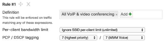
Define Traffic Shaping Rules
Use traffic shaping to offer application traffic the necessary bandwidth. It is important to ensure that the application has enough bandwidth as estimated in the capacity planning section. Traffic shaping rules can be implemented to allow real-time voice and video traffic to use additional bandwidth, and the rules can be used to block or throttle applications such as P2P, social networks.
- Go to Wireless > Configure > Firewall & traffic shaping and choose the SSID from the SSID drop-down menu at the top of the screen.
- Click the drop down menu next to Shape traffic and choose Shape traffic on this SSID, then click Create a new rule.
- Click Add + and select 'All voice & video conferencing'
- Set Per-client bandwidth limit to 'Ignore SSID per-client limit (unlimited)' and click Save changes.
Convert Multicast to Unicast
Cisco Meraki APs automatically perform a multicast-to-unicast packet conversion using the IGMP protocol. The unicast frames are then sent at the client negotiated data rates rather than the minimum mandatory data rates, ensuring high-quality video transmission to large numbers of clients. This can be especially valuables in instances such as classrooms, where multiple students may be watching a high-definition video as part a classroom learning experience.