
RF Profiles
日本語版はこちら(Japanese)
Overview
Each wireless network is unique and faces its own unique challenges in coverage, configuration, and design. It is common for IT administrators to deploy several APs configured for a specific RF scenario (for example, a large, crowded auditorium) in one location, while also needing to deploy several networked APs elsewhere for a different RF scenario (for example, a small lobby). The radio setting requirements for these two groups of APs can look quite different even though all of the access points are on the same network.
This article will outline the RF Profiles feature and how it can be used to deploy customized radio settings to groups of MR Access Points.
Note: Settings throughout this article pertaining to 6GHz configurations are only applicable to WiFi-6E Access Points
Learn more with these free online training courses on the Meraki Learning Hub:
RF Profiles
RF Profiles provide more control over radio settings for APs within a specific network. This feature is helpful especially in complex wireless deployments as multiple RF profiles can be defined and applied to APs within a network. By using RF profiles customers can now customize the RF settings for different areas at a property at scale and no longer need to manually make changes for each AP.
RF Profiles can be used with all APs running firmware MR25.x. After defining profiles, customers can additionally override the settings from the Overview tab. By default, two RF profiles are defined for every network. One for indoor APs and one for outdoor APs. In addition, the Basic Mixed Profile is used on APs (such as the CW9179F) that can be installed in both indoor and outdoor environments. For these APs, you cannot use a different default profile, or you will receive this error: “You cannot assign a mixed nature AP to a basic indoor or outdoor profile.”
APs within a network are automatically assigned to the corresponding RF profile. Network administrators can additionally check the assigned RF profile to a particular AP by going to Wireless > Configure > Radio Settings and checking the Overview tab.
Using RF profiles is not mandatory. Administrators that do not want to use RF profiles can leave the AP in the default profiles and APs will inherit settings based on old radio settings page as described in Mapping to Default profiles. If any settings need to be changed in the default profiles then administrators have to define new profiles and apply the profiles to APs accordingly.
A maximum of 50 RF profiles can be defined.
Default Templates
Administrators can also select from five predefined templates for typical auditoriums, open offices, and outdoor coverage scenarios to help IT quickly configure wireless settings for maximum performance. After creating or selecting a specific RF Profile, settings (which comprise the profile) can then be applied, en masse, to groups of APs.
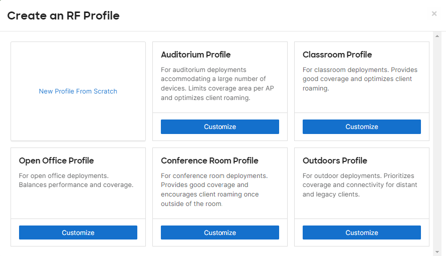
The five profiles are as follows:
-
Auditorium: This profile is designed for open auditorium deployments accommodating a large number of devices. TX power is in the lower range.
-
Classroom: This profile is designed to accommodate a medium number of devices in a classroom. TX power is in the lower range.
-
Open Office: This profile is designed to accommodate a medium number of devices in an open office environment. TX power is in the medium range.
-
Conference Room: This profile is designed to accommodate a medium number of devices in an open office environment. TX power is in the lower range.
-
Outdoors: This profile is configured to accommodate outdoor deployments. TX power is in the high range.
| Profile | 2.4GHz | 5GHz | 6GHz | Minimum bitrate (Mbps) (2.4/5GHz) |
Minimum bitrate (Mbps) (6GHz) |
Channel Width (5GHz) | Channel Width (6GHz) | |||
| min (dBm) | max (dBm) | min (dBm) | max (dBm) | min (dBm) | max (dBm) | |||||
| Auditorium | 5 | 11 | 8 | 14 | 8 | 30 | 24 | 12 | 20 | Auto |
| Classroom | 8 | 14 | 11 | 17 | 8 | 30 | 24 | 12 | 20 | Auto |
| Open Office | 11 | 17 | 14 | 20 | 8 | 30 | 12 | 12 | 20 | Auto |
| Conference Room | 8 | 14 | 11 | 17 | 8 | 30 | 12 | 12 | 20 | Auto |
| Outdoors | 17 | 23 | 17 | 23 | 8 | 30 | 6 | 12 | Auto | Auto |
All profiles are designed considering standard building materials. If older building materials are being used (eg: cinder block) settings might need changing. RX-SOP values have been set to default and need to be changed on a case by case basis. It is recommended to consult a wireless expert before changing RX-SOP values and also refer to the RX-SOP section for additional details.
Create Custom Profile/Edit an Existing Profile
Administrators can create custom profiles or edit existing profiles as required, depending on use case. The following options can be set as part of RF profiles:
Profile Name
Name of the profile. Usually named after a particular location within a venue or a unique identifier that can denote the RF profile for a particular application. Eg: Concessions stand
Band Selection
Specific bands can be set on All SSIDs or Per SSID basis in an RF profile.
- All SSIDs selection provides dual band operation (with or without band steering), 5GHz or 2.4GHz configuration options.

- Per SSID selection allows setting target SSID to 2.4 GHz, 5 GHz, dual band, or dual band with band steering
- Select the 2.4 GHz checkbox to set an SSID to 2.4 GHz only
- Select the 5 GHz checkbox to set an SSID to 5 GHz only
- Select both 2.4 GHz and 5 GHz checkboxes to set an SSID to dual band operation
- Select all three 2.4 GHz, 5 GHz, and Band steering checkboxes to set an SSID to dual band operation with band steering

If 2.4 GHz support is needed, it is recommended to use 'Dual-band with band steering' to ensure support for 2.4 GHz devices while dual band devices will be steered to use the 5 GHz band. For more details refer to the Band Steering Overview article. If 2.4 GHz support is not needed, it is recommended to use “5 GHz band only”. Testing should be performed in all areas of the environment to ensure there are no coverage holes.
The individual selected bands in Wireless > Configure > Radio Settings > General > Band Selection do not reflect in the Enabled and Broadcasting columns of the BSSID details found in Wireless > Monitor > Access Points. See Access Point Status Page for more information.
Minimum bitrate configuration
Customers can set a minimum bitrate in this section. Using this option minimum bitrate can either be set on a per band basis or per SSID basis. It is recommended to use minimum bit rates per band. Using minimum bit rate on a per SSID basis will yield different experiences for each SSID and may also lead to coverage holes if not planned accordingly. Minimum bit rate per SSID can be used in applications where only known device types will be used and performance needs to be optimized for specific device types. It is recommended to consult a wireless expert before using a minimum bit rate per SSID.

If a minimum bit rate is set to be configured on a per band basis, the minimum bit rate slider appears in 2.4 GHz and 5 GHz radio settings section as shown below:

A minimum bitrate can also be configured on a Per SSID basis as shown below.


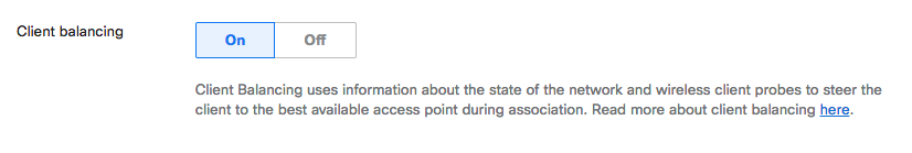
Client Balancing
Customers can enable/disable client balancing in this section. As the name suggests, the feature tries to balance clients across APs. Additional details about the feature can be found here.
2.4 GHz/5 GHz/6 GHz Radio Settings
Channel Width - Available only on 5/6 GHz
Using this option, customers can set channel width for all SSIDs used on the AP that are assigned to the RF profile. Customers can choose 20 MHz, 40 MHZ, 80 MHz, 160MHz, or Auto. If using Auto option, Cisco Meraki APs automatically select channel width based on environmental conditions. It is recommended to use 20 MHz channel width for most enterprise deployments.


Since the Manual 5 GHz Channel Width setting overrides the default Auto Channel setting on MR 25.1 and higher, the "Overrides applied to...of these APs." notification will appear underneath the RF Profile name.
On the 6 GHz band, AutoRF can assign channels outside the Preferred Scanning Channels (PSC) group if they are selected in the RF Profile list when using 20 MHz channels.
Channel Assignment Method
This option allows administrators to customize the channels to be included for AutoChannel. By clicking on Change channels used by AutoChannel, administrators are able to select a list of channels available for selection as shown below. Channels highlighted will be used as part of the AutoChannel algorithm. To quickly include or exclude DFS channels from the list of channels used by AutoChannel, the Select DFS channels or Deselect DFS channels button can be clicked.

Autochannel on 2.4 GHz only uses channels 1, 6 and 11. Administrators can remove only one of the three channels. If non-standard channels need to be used manual overrides can be done from the Overview page.

Using AutoChannel, Cisco Meraki access points automatically adjust the channels of their radios to avoid RF interference (Both 802.11 and non-802.11) and develop a channel plan for the Wireless Network.
DFS events trigger channel changes. APs may select channels outside of the RF profile if there are only DFS channels available on the list and there are multiple DFS events within 15 minutes. If that happens, Meraki dashboard assigns a channel within the RF profile list after 15 minutes.
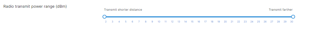
Transmit Power Range
Using this option, customers can set a range for the target Transmit (TX) power at the radio. Although, AutoTX Power tries to optimize the TX power based on the overall RF environment. In complex environments, it may be necessary to limit the range depending on the requirements.
Previously, 2.4GHz had a range of 5dBm to 30 dBm, whereas 5GHz had a range of 8dBm to 30dBm. Currently, on all bands including 6GHz, the allowed range is 2 dBm to 30 dBm since the AutoTX operates in that range.
Transmit power is a component of the Effective Isotropic Radiated Power (EIRP) calculation. EIRP is calculated by adding the transmit power of the radio, the gain of the antenna, and the contribution of transmit beamforming (which depends on the number of spatial streams), while subtracting the loss of the cable between the radio and antenna.
EIRP = Transmit Power (dBm) + antenna gain (dBi) + 10 log10(number of spatial streams) (dBi) – cable loss (dB)
RX-SOP
Using RX-SOP values, the receive sensitivity of the AP can be controlled. The higher the RX-SOP level, the less sensitive the radio is and the smaller the receiver cell size will be. The reduction in cell size ensures that clients are connected to the nearest access point using the highest possible data rates. RX-SOP can be configured in the range of -65 dBm to -95 dBm.
As an example, using -75 dBm will result in a smaller coverage footprint as compared to -85 dBm since RX-SOP values are on a negative scale.
It is strongly recommended to use RX-SOP only after consulting a wireless expert.
Once customers click on Set RX-SOP under the Radio Transit power range option, a warning message will show up indicating to proceed with caution as shown below.

After customers click on proceed, an option to enable/disable RX-SOP will be presented as shown below.

If Enabled is selected, a slider to configure the RX-SOP value shows up.

802.11ax
Also known as WiFi 6, 802.11ax is the latest WLAN standard. Some (older) wireless clients may be unable to communicate on wireless networks using 802.11ax. Disabling 802.11ax will make access points communicate using 802.11ac or 802.11n, depending on access point capability.

Max Radio Power Limitations
When a wireless network is set to a high dBm or "Always use 100% power" under Wireless > Configure > Radio settings > Radio power, all Access Points in the network will set their radios to the set value or highest allowed transmit power (whichever is lower). The actual maximum power may vary between APs due to regulatory limitations or environmental factors.
Some factors that may limit a given AP's max transmit power include:
- Regulatory Domain
Wherever an AP is deployed, it will be subject to the requirements of its regulatory domain. Different regulatory domains may have different rules regarding maximum transmit power, so APs set to high power may have their actual maximum power limited based on their location. Note that these regulations may also differ between indoor and outdoor APs.
- Channel Selection/Band Edge
Certain channels, due to their adjacency to non-802.11 channels, may require a lower transmit power to prevent transmissions from extending into these non-802.11 channels. If an AP uses one of these band-edge channels, its maximum power may be limited.
- Bit Rate
Transmissions with a fast bit rate have a higher chance of being distorted due to the additional complexities involved in transmitting wireless data at high speeds. To reduce the potential for distortion, radios set for a higher bit rate will need to reduce their transmit power. This can further limit the maximum transmit power of a given radio.
- AP Model
The transmit power limit by bit rate (data rate) varies between AP models. Check the RF Performance Table within the AP's datasheet in order to verify the maximum TX power an AP can operate at (regardless of the regulatory domain authorization).
Setting a wireless network to use 100% power will cause the respective AP's to negotiate using the highest possible transmit power. However, due to the factors outlined above, the transmit power observed may be lower than anticipated.
Antenna Beam State
APs (such as the CW9179F) that can be intsalled in both indoor and outdoor environments can use the Antenna beam state configuration on the Basic Mixed Profile. The beam state can toggle between three different antenna options built into the AP. For example, if an AP has external antenna connectors, you could have a narrow beam antenna or a wide beam antenna connected to that AP. With the CW9179F, this is all built into the AP itself and you change the can setting within the Basic Mixed Profile.

Boresight mode means "straight" and is the “narrow” beam setting for the AP. In the image above, Boresight is 35x35 degrees in both the 5GHz and 6GHz bands. It is 70x70 in 2.4GHz.
Wide mode makes the following changes:
- It changes 6GHz to 70x35. Therefore, it is widening the coverage while maintaining the same elevation of 35 degrees.
- In the 5GHz band there are two radios. While they remain 35x35, they are steered away from Boresight to match the 70 degree width of the 6GHz coverage, as illustrated in the image above.
Front-and-back mode keeps the 5GHz high band radio and the 6GHz radio at 35x35 and is transmitting out of the front of the AP. The 5GHz low band radio and the 2.4GHz radio are switched to the N connectors located on the back of the AP where the user can attach an external antenna.
For example, here are the officially supported antennas for the CW9179F:
- CW-ANT-T-D3-N
- AIR-ANT2588P4M-NS
- AIR-ANT2566D4M-R/RS
- AIR-ANT2566P4W-R/RS
Below is an example of an indoor and outdoor AP (CW9179F) with the CW-ANT-T-D3-N antennas connected.

(MR 33.1.1) 3 Radio Support
Tri-Radio VS Quad-Radio Mode Support
The Cisco Wireless 9179F supports software-configurable radio modes to provide maximum flexibility across various regulatory domains and deployment use cases. While Quad-Radio mode remains the default for maximum capacity, Tri-Radio mode is introduced to simplify channel planning and device compatibility in the 5GHz spectrum.
Why choose Tri-Radio Mode?
-
Simplified Channel Planning: In regions with a limited number of 5 GHz channels, band-locking (5 GHz-Low/High) can over-constrain the available spectrum. Tri-Radio mode allows for full range access of 5 GHz channels, reducing co-channel interference.
-
Enhanced Legacy Device Support: In industrial environments such as warehouses, legacy clients (e.g., older handheld scanners) often do not support DFS channels. Tri-Radio mode makes it easier to assign non-DFS channels across the entire 5 GHz band without the restrictions of a split-radio architecture.
-
(NEW) Tri-Radio Mode (2.4 GHz, 5 GHz, 6 GHz): Enables three client-serving radios. In this mode, the 5 GHz radio is no longer band-locked, allowing it to utilize any available 5 GHz channel.

Configuration
-
Navigate to Wireless > Configure > Radio Settings.
-
Locate the RF Profile assigned to the CW9179F you wish to modify, or create a new one.
-
Scroll down to the Flex Radio section.
-
Under Flex Radio (XOR), choose the desired radio configuration:
4 radios
3 radios
-
2.4 GHz: Best for maximum range and legacy device support.
-
5 GHz: Best for high-density performance.
-
6 GHz: (On supported Wi-Fi 6E/7 models) Best for high-throughput, clean spectrum.
-
Save Changes.

Boresight (Default)- Quad Radio Mode
When the Antenna beam state is configured to Boresight Quad-Radio Mode the (2.4 GHz, 5 GHz-L, 5 GHz-H, 6 GHz) client-serving radios are enabled. In this mode, the 5 GHz band is split into two band-locked radios (Lower and Upper 5 GHz bands). This is ideal for high-density environments where maximum throughput is required.

Note: Dual 5 GHz Mode If you have access points that can broadcast 5GHz with two different radios. These radios are indicated by 5-lo and 5-hi above.
If you want to broadcast on both radios, select at least one channel for each radio.

Note: When in 3 radio mode, only Boresight is supported.
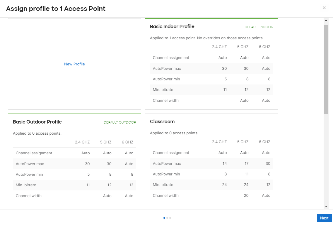
Assigning RF Profiles to APs
The RF profile can be assigned to a specific AP or multiple APs in bulk on the Wireless > Configure > Radio Settings page in the dashboard. On the list of APs, select the checkbox next to each AP that you would like to apply the profile to, then use the Edit Settings drop-down and select Assign Profile. This will allow you to choose which profile you would like to be assigned to the selected devices. Once the profile selection has been made, the proposed changes will be displayed on the dashboard for confirmation before they are applied to the selected devices.

When applying RF Profiles, administrators have the option to retain certain settings as shown below.

After assigning RF profiles, make sure the selected APs are unselected as they will not be automatically unselected.
After RF profiles have been assigned, TX power and channel assignment changes might take up to 60 minutes to reflect changes as calculations are done through Meraki dashboard. If the change is to disable any particular band, the changes will take effect immediately.
A maximum of 1500 APs can be assigned to each RF profile. Note that for customers using a template to manage their networks, this limit also applies; a maximum of 1500 APs can be assigned to each RF profile in a template.
Please be aware that making RF profile changes can cause clients to disassociate from APs resulting in a brief service disruption for wireless networks.
Turning off an MRs radio (Deep Sleep)
More more information regarding this feature, please feel free to refer to this document.
Antenna Bulk Assignment
From Radio Settings, antennas can be assigned to the desired Access points.
This can be achieved by:
- Select the desired Access Point by clicking on the checkbox
- Click on "Edit Settings" and select "Bulk Edit settings"

- Select "Antenna / antenna gain" and click Next

- Select the desired antenna and click on "Review changes".

- Click on "Apply Changes", assignment for the APs selected will be updated at this point.

RF Profiles and Old Radio Settings
When administrators go to Wireless >Configure > Radio Settings they will be directed to the radio settings page that includes RF Profiles and administrators need to click on View old version to go to the old page that does not have RF profiles.
If custom RF profiles have been configured and assigned to APs, warnings will be shown to users asking them to make configuration changes using the new page.

If options on old radio settings need to be unlocked, then APs should be assigned to default profiles and any new RF profiles need to be deleted. Administrators can then go back to the old page and make changes.
Regulatory domain
After RF Profiles is enabled for the organization, regulatory domain settings will be moved to Network-wide → General. The Wireless Options section on the Access Control page will show a pop-up message asking administrators to configure settings using RF Profiles as shown below:

Clicking on Go to RF Profiles will direct to the administrators to the new radio settings page but, if Dismiss this message is selected the message will be minimized and the settings will be displayed with a note directing administrators to the new RF Profiles page as shown below:

Mapping to Default Profiles
Once customers move to the new page with RF profiles, APs are automatically assigned to either an Indoor or Outdoor profile. All indoor APs in the network will be assigned to the default indoor profile and outdoor APs will be assigned to the outdoor profile. After defining new profiles, APs can then be moved to respective profiles depending on design needs.
Band selection
Band selection and bit rate selection in default profiles is based on the current SSID settings. If the settings are the same across all active SSIDs band selection will be set on a Per AP basis and bitrate will be set to per band and both bands will have the same value. If the settings are different for each SSID then band selection and bitrate will be set on a per SSID basis and the configuration for each SSID will be retained.
Transmit power settings
Transmit power range will be set to 5 - 30 dBm for 2.4 GHz and 8 - 30 dBm for 5 GHz if Enable Automatic power reduction is selected on the old radio settings page. If Always use 100% power is selected transmit power range will be set to 30 dBm for both bands. If any APs have TX power and channel set manually, the settings will be retained and the AP will be counted towards one of the APs that have overrides. Rx-SOP will be set to a default value of -95 dBm.
Channel width
Channel width is set depending on the settings on the old radio settings page. On 2.4 GHz the APs will always default to 20 MHz and for 5 GHz the AP will use the value from the channel width drop-down.
Flex Radio
Wi-Fi 6E ad Wi-Fi 7 APs support a software defined flex radio which can be toggled between a 5 GHz and 6 GHz. This provides an option to operate the Access Point in either a dual 5 GHz configuration or a true tri-band configuration. Tri-band configuration unlocks the use of new spectrum in the 6 GHz frequency range which provides additional channels to increase throughput and reduce interference and noise from legacy devices. 6 GHz support ensures that the Access Point supports future technologies.
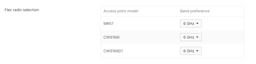
To select only 5-hi or 5-lo channels for the 5 GHz band in Channel assignment method, follow these steps:
- Set the Flex Radio Band Preference to 6 GHz for all APs and save the configuration.
- Make the required changes to the 5-hi or 5-lo channel selection and save the configuration.

- Proceed to change the Flex Radio Band Preference as required.
APs (like CW9166I and CW9178I) that have a flex radio that supports 5 + 6 GHz and are deployed in a regulatory domain that does not support 6 GHz the Flex radio will use 5 GHz and defaulting to Dual 5 GHz operation.
The Flex radio settings will not be present in the RF profile when deployed in a regulatory domain that does not support 6 GHz. This will lock each AP and 5 GHz radio into a 5-hi and 5-lo mode of operation where only specific UNII bands and channels are allowed per radio.
Example: When the CW9166I is operating in Dual 5 GHz mode, the 5 GHz radio in slot 1 operates only in the UNII-1 and UNII-2 bands (channels 36 to 64), and the radio in slot 2 is locked to the UNII-2-Extended and UNII-3 bands (channels 100 to 165).
If a single 5 GHz radio is desired one of the radios can be disabled on the AP manually but the active radio will still be locked to the 5-hi or 5-lo channels and it will not get access to all channels.