
CWA - Central Web Authentication with Cisco ISE
Cisco Identity Services Engine (ISE) may be used for guest management when paired with Meraki Access Points. Cisco ISE is another option for authorizing users, enabling many additional business use cases.
Meraki APs will pass necessary information over to Cisco ISE using MAC-based authentication and honor a Uniform Resource Locator (URL) redirect that is received from the Cisco ISE Server. Using change of authorization (CoA), the Cisco ISE server can ensure that the correct authorization is applied to the end user devices based on the authentication status.
Expected Packet Flow
.jpeg?revision=1&size=bestfit&width=890&height=617)
-
Client machine associates to the web authentication SSID
-
Client MAC address is sent to RADIUS server as a username and password (Access-Request) by MR, and the MR responds to the client machine acknowledging the association request
-
ISE server responds with an RADIUS Access-Accept and a redirect URL
-
Client machine gets an IP address and DNS server address through DHCP
-
Client machine tries to reach a webpage which results in an HTTP GET packet
-
MR intercepts the GET packet and sends redirect URL instead (with webpage hosted on ISE)
-
Client machine authenticates on the ISE web portal
- RADIUS server then sends a CoA request (CoA requests work on UDP Port 1700) with a request to re-authenticate, also indicating that user is valid
- MR sends CoA-ACK
- MR Authenticator sends an Access-Request with existing client machine's session-ID and MAC address
-
ISE server then responds back with Access-Acccept and any extra ISE functions after client's successful authentication to web portal
-
Client is allowed access to the network
Configuration
The following sections of this guide will outline a configuration example with using Cisco ISE as the guest management system which is also hosting the captive portal.
Meraki Access Point dashboard configuration
The Meraki Access Point configuration is outlined below all on the Access Control Page for a particular SSID (Wireless > Configure > Access Control).
Configure MAC-based authentication
Select MAC-based access control from the Security section of the access control page.
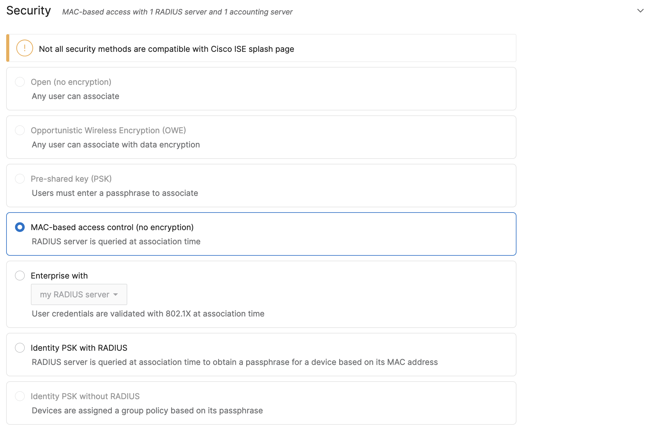
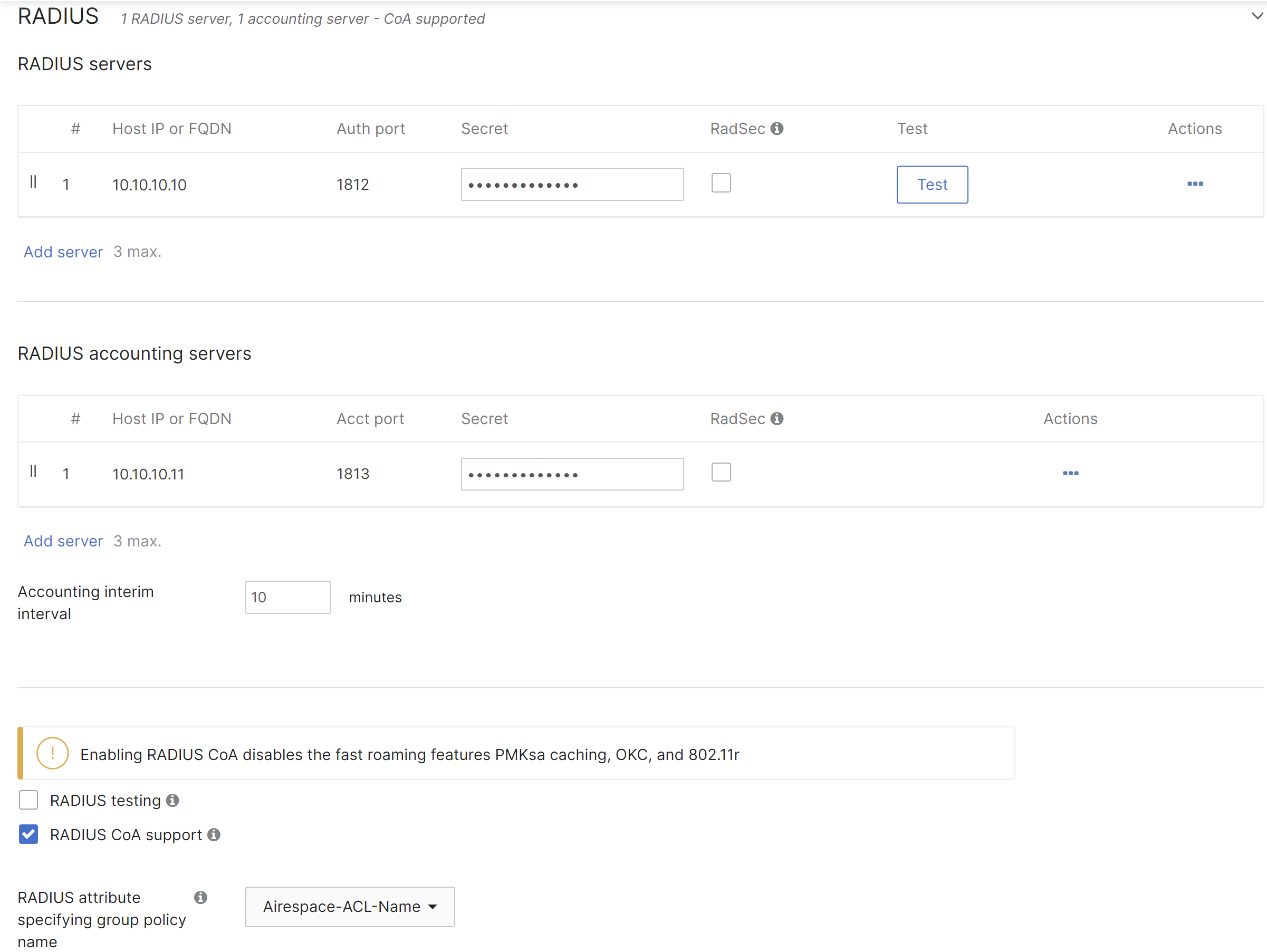
Enter the details for the RADIUS server including the IP address, port, and secret. If using Group Policies select Airspace-ACL-Name for the RADIUS attribute specifying the group policy name. The Airspace-ACL-Name must match the name of one of your group policies configured under Network-wide > Group Policies. Enable CoA support if there is a requirement to change the attributes of an authentication, authorization, and accounting (AAA) session.
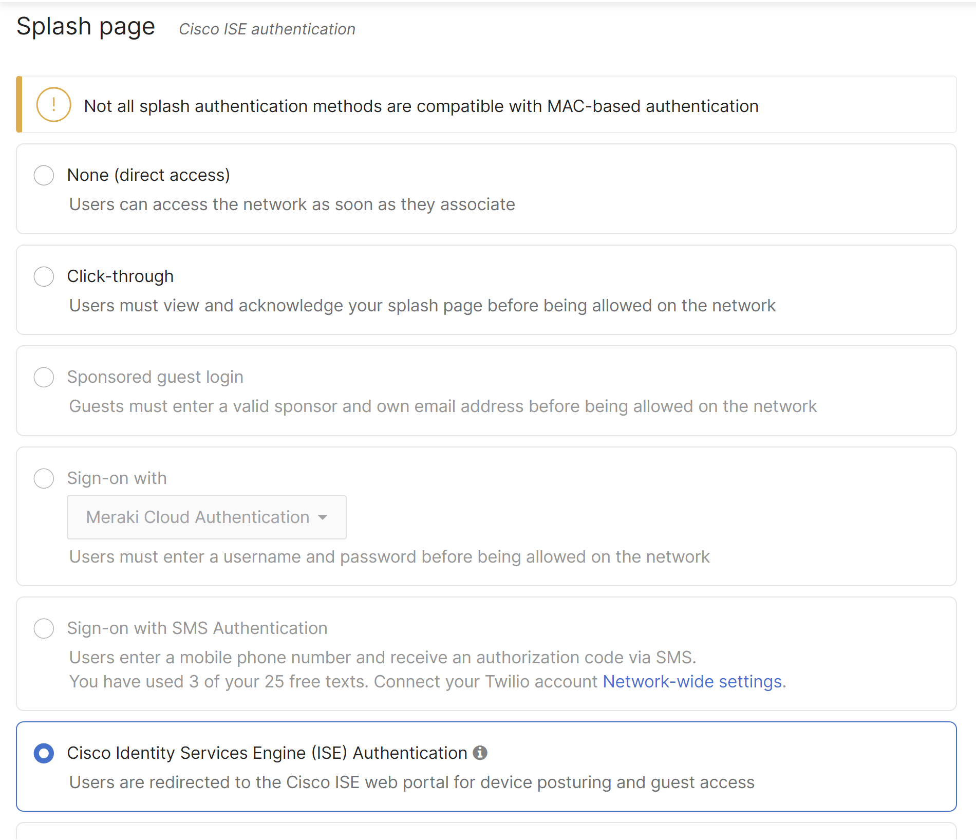
Configure CWA for Splash page
Select Cisco Identity Services Engine (ISE) Authentication in the Splash Page section of the access control page. This setting will honor the Cisco custom url-redirect attribute sent from Cisco ISE.
Configure the Walled Garden
The IP address of the Cisco ISE server needs to be added to the Walled garden under Advanced splash settings to ensure that a client will be permitted through the Walled garden before being authenticated by the Cisco ISE server.

Note: DNS traffic is permitted by default through the Walled garden
Even though a wireless client connects and successfully authenticates to an SSID using CWA, you still see it as Not Authorized in the Splash field of the client's detail page. If you need this behavior to be changed and have dashboard reflect the correct splash authentication state please reach out to your account manager and/or use the Give your feedback option to make the request.
An access policy type of Hybrid Authentication with the Increase Access Speed option enabled will result in CWA failing. Please uncheck the Increase Access Speed option if you are planning to use CWA.
Configure post-authentication access to the Cisco ISE server
Some versions of iOS, Windows, and Android require continued access to the Cisco ISE server through the portal TCP port after Central Web Authentication (CWA) completes. This behavior may affect Guest and BYOD deployments.
If access to the Cisco ISE server through the portal TCP port is blocked after authentication, users may successfully authenticate but subsequently lose network connectivity.
A packet capture may show the client attempting to access the Cisco ISE server after authentication has completed. If this access is blocked, the Guest or BYOD authentication flow may fail.
To allow post-authentication access to the Cisco ISE server, use one of the following methods:
Configure a firewall rule
- Navigate to Wireless > Firewall & traffic shaping.
- Select the affected SSID.
- Verify the Wireless clients accessing LAN setting.
- If Wireless clients accessing LAN is set to Deny, create one or more allow rules that permit traffic to the Cisco ISE server IP addresses.
- Alternatively, set Wireless clients accessing LAN to Allow.
- Save the configuration.
Configure a group policy
- Navigate to Wireless > Access control.
- Select the affected SSID.
- Configure the Airspace-ACL-Name RADIUS attribute to specify a group policy that permits traffic to the Cisco ISE server.
- Save the configuration.
Note: This behavior is caused by the client operating system and cannot be prevented by Cisco. For additional information, refer to Cisco bug CSCvx28883.
Disable CNA
As of Cisco ISE 2.2, Apple CNA is supported for Guest and BYOD. Beginning July 26th, 2017, Apple CNA and Android captive portal detection are enabled by default on Cisco Meraki MR access points. On iOS 7+ and OS X, the client will automatically launch a mini-browser (CNA) that takes the user to the splash page to complete authentication and gain access to the network. Android devices will display a notification on the device prompting the user to sign into the Wi-Fi network. Tapping the notification will launch the device browser and direct the user to the splash page. To disable CNA and captive portal detection, append the following 17.0.0.0/8 IP range and domain names to the walled garden below the ISE server address as shown below (192.168.140.37/32 being the ISE IP address in this example):

Copy/paste:
17.0.0.0/8
captive.apple.com
*.apple.com
*.appleiphonecell.com
*.ibook.info
*.itools.info
*.airport.us
*.thinkdifferent.us
clients3.google.com
*.gstatic.com
Disabling CNA will require that users manually open their web browser before being presented with the splash page. Applications on the user's device that require Internet connectivity will not function as expected until the user has opened their web browser and completed authentication via the splash page. If your network contains Apple devices running iOS 14/macOS Big Sur and newer operating systems , DHCP option 114 can be leveraged instead of Apple's legacy Captive Portal networks. For additional info, please see Apple's How to modernize your captive network documentation.
Cisco ISE Configuration
The following sections focuses on Cisco ISE 2.4 and it will present a basic configuration with default web portal from Cisco ISE. For more information about web portal customization please look into ISE documentation.
Adding Managed Network Devices
MR access points acting as authenticators (devices through which AAA requests are sent to Cisco ISE) need to be added to ISE before Access-Request will be answered, it will by default not answer any requests.
To add a new device:
-
In Cisco ISE, choose Administration > Network Resources > Network Devices.
-
From the Network Devices navigation pane on the left, click Network Devices.

-
Click Add, from the action icon on the Network Devices navigation pane or click an already added device name from the list to edit it.
-
In the right pane, enter the Name and IP Address. As for the mask, you can add devices inside a network using /24, or as needed to avoid manually importing several APs.
-
Check the Authentication Settings check box and define a Shared Secret for RADIUS authentication. This must match the Secret entered for the RADIUS server when configuring the SSID in Dashboard.

- Click Submit
Once a device is added, it will show up on the device list in ISE.

Creating Results for Rules
A new results needs to be created where the redirection will be specified.
To do this, go to “Policy > Results”. Click on Authorization and Authorization Profiles.

Click on “Add”
-
Name this authorization profile.
-
On Common Tasks, select “Web Redirection (CWA, MDM, NSP, CPP)”, choose Centralized Web Auth, on ACL “NULL” and Value “Self-Registered” (These values can change depending on your needs.
Optionally, Static IP can be used to not used a DNS server, however, this is not recommended because the IP of the ISE server will be clear text and visible for the end client.

Enabling Policy Sets
Cisco ISE supports policy sets, which allow grouping sets of authentication and authorization policies, as opposed to the basic authentication and authorization policy model, which is a flat list of authentication and authorization rules. Policy sets allow for logically defining an organization's IT business use cases into policy groups or services, such as VPN and 802.1X. This makes configuration, deployment, and troubleshooting much easier.
In Cisco ISE, choose Administration > System > Settings > Policy Sets.
Creating a Policy Set
-
Click on Policy > Policy Set

-
Click the plus (+) sign or click on the settings icon and Create above to create a new policy set.
-
Enter the Name, Description and a Condition for this group policy.
-
Click on Condition, a new menu will show, match the condition necessary, per SSID policy sets are recommended, therefore, attribute “Radius·Called-Station-ID” ENDS WITH “<SSID name>” is the preferred option. Click “Use” after configuring this step.
![]()
-
Define allow protocols, by default “Default Network Access” can be used.
-
Click on “Save”

Create Authentication Policy
-
Click on “View” policy by clicking on the right arrow.
-
Click on ”Options”
-
Change “If user not found” to CONTINUE

Create Authorization Policy
Two rules are required in Authorization Policies for Central Web-Auth, one rule will prompt the redirection and the second rule will grant access once the client machine has passed web page authentication.
-
Click on Authorization Policy
![]()
-
Click on the (+) sign or on the settings Icon to create a new rule.
-
Click on “Condition”. a new window will pop up. In this window, the method of the client requesting access can be selected.
-
Look for Called-Station-ID, and match it to the name of the SSID.
-


-
Click “Use”
-
Select on “Results”, the name of the profile created for redirection, in this case it is “CWA”.
For second rule click on the Action Icon and select “Insert new row above”

-
Click on “Condition” a new window will pop up, in this window the method of the client requesting access can be selected.
-
Look for “IdentityGroup:Name”

- Select “In” and “Endpoint Identity Groups: GuestEndpoints”.

-
Click on “Use”.
-
Select on “Results” the profile called “PermitAccess”
-
Click Save.
Both rules should be created and should look like the image below, order is very important.

Note: If Active directory is being used, it is a recommended practice to match the AD group where most of the users exist for better security and functionality.
Within the Passed Web conditions, Network Access-Use Case EQUALS Guest Flow is not supported with Meraki APs. If this condition is used, the client's session is reset every time they roam and will have to reauthenticate.