
MR42E Installation Guide
The Cisco Meraki MR42E is a dual-band enterprise class 802.11ac cloud-managed access point with support for external antennas. Designed for high capacity and high density, the MR42E meets the needs of the most demanding environments. The access point also includes a third radio dedicated to optimizing the RF environment and securing the airwaves along with a BLE radio for supporting IoT applications.
Package Contents
The MR42E package contains the following:
- MR42E Cloud-Managed Access Point
-
Mount cradle including built-in level tool
- Drop ceiling mount kit
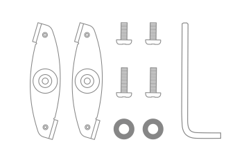
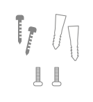
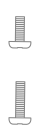
- Wall screws, wall screw anchors, and security screws
- Spare hardware
Understanding the MR42E
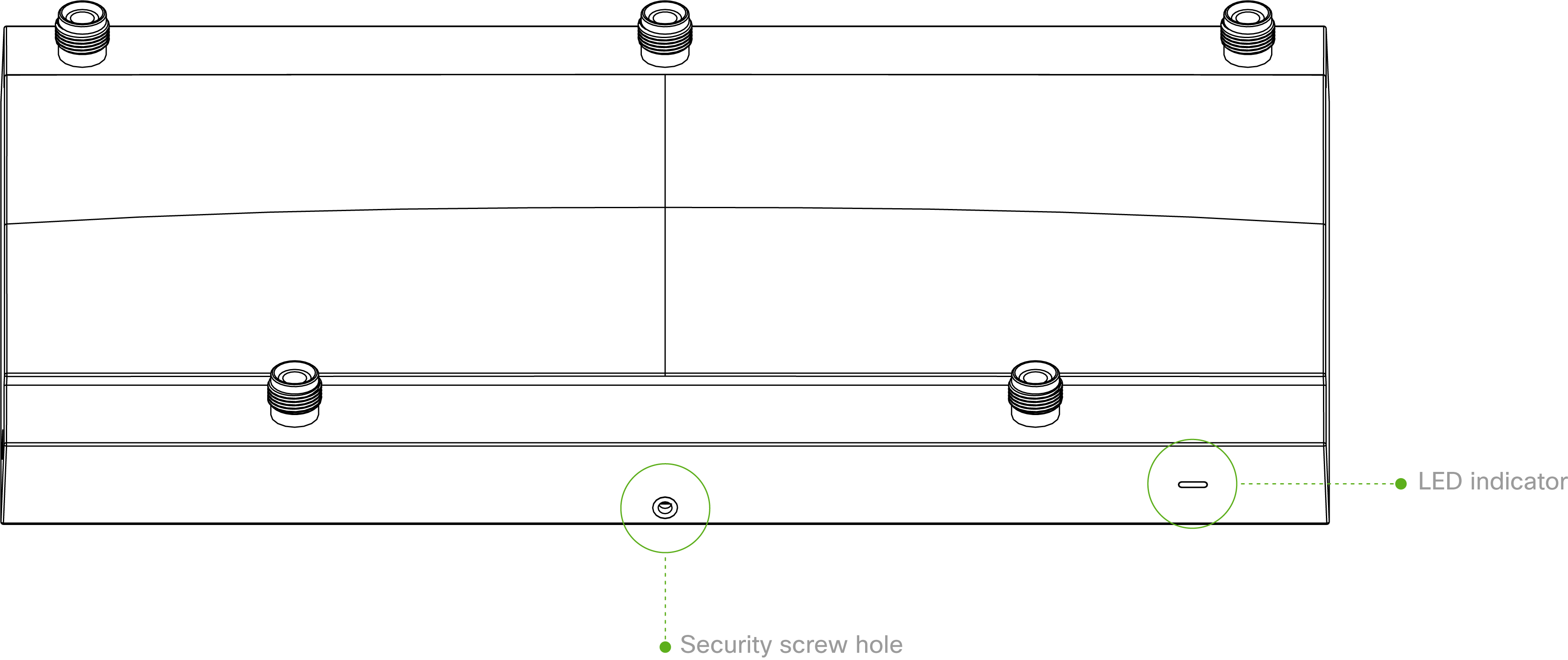
Your Meraki MR42E has the following features:
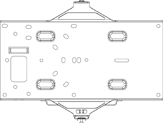
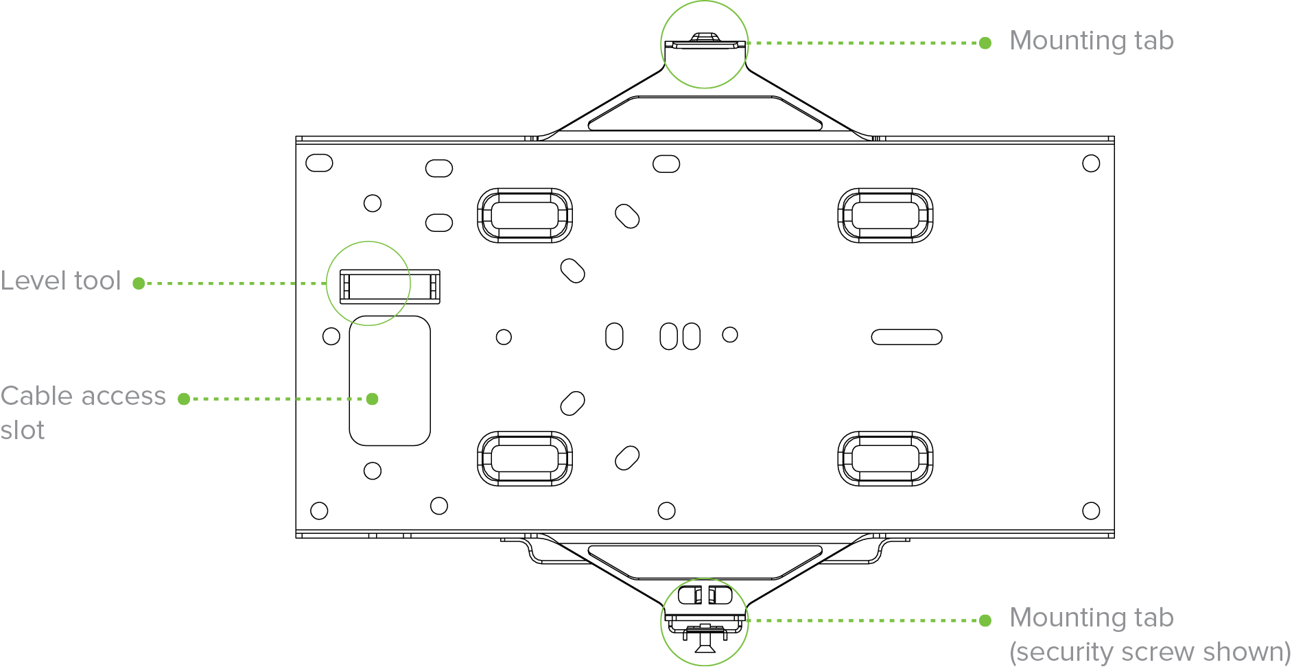
The mount cradle has the following features:
Security Features
The MR42E features multiple options for physically securing the access point after installation:
- Security screw – The accessory kit includes screws that can be used to secure the access point to the mount cradle. Engaging the security screw prevents accidental dislodging and theft.
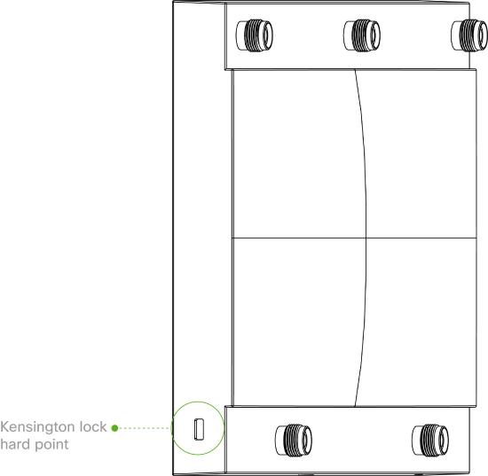
- Kensington lock – The access point contains a hard point that allows it to be secured to any nearby permanent structure using a standard Kensington lock.
External Antenna Ports
The MR42E has 5 external antenna ports:

The ports labeled 2.4/5 is meant for client serving radios

The port labeled Scan is meant for scanning wireless channels

The port labeled IoT is meant for BLE applications
Ethernet Ports
The MR42E features a Gigabit Ethernet RJ45 port that accepts 802.3at and 802.3af power (labeled “Eth0, PoE”). This port should be used for uplink to your WAN connection.

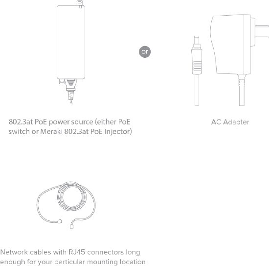
Power Source Options
The MR42E access point can be powered using either the Meraki AC Adapter, PoE Injector (both sold separately), or a third-party PoE switch.
The MR42E will function in low power mode when powered by a 802.3af power source. While in low power mode, the MR42E will disable its Air Marshal radio as well as two out of three transmit streams on the 2.4 Ghz band. Despite being in low power mode, the device can still supply full 802.11ac capabilities.
Factory Reset Button
If the button is pressed and held for at least five seconds and then released, the MR42E will reboot and be restored to its original factory settings by deleting all configuration information stored on the unit.
LED Indicators and Run Dark Mode
Your MR42E is equipped with a multi-color LED light on the front of the unit to convey information about system functionality and performance:
- Orange - AP is booting (permanent Orange suggests hardware issue)
- Rainbow - AP is initializing/scanning
- Blinking Blue - AP is upgrading
- Green - AP in Gateway mode with no clients
- Blue - AP in Gateway mode with clients
- Blinking Orange - AP can't find uplink
The MR42E may be operated in “Run Dark” mode for additional security and to reduce the visibility of the access point. In this mode, the LED will not be illuminated. This mode may be enabled through Meraki dashboard.
NOTE: Blinking Green LED indicates that the device is in site survey mode. Please see the Conducting Site Surveys with MR Access Points for more details.
Pre-Install Preparation
You should complete the following steps before going on-site to perform an installation.
Configure Your Network in Dashboard
The following is a brief overview only of the steps required to add an MR42E to your network. For detailed instructions about creating, configuring and managing Meraki wireless networks, refer to the online documentation (documentation.meraki.com).
- Login to http://dashboard.meraki.com. If this is your first time, create a new account.
- Find the network to which you plan to add your APs or create a new network.
- Add your APs to your network. You will need your Meraki order number (found on your invoice) or the serial number of each AP, which looks like Qxxx-xxxx-xxxx, and is found on the bottom of the unit. You will also need your Enterprise license key, which you should have received via email.
- Go to the map / floor plan view and place each AP on the map by clicking and dragging it to the location where you plan to mount it.
Check and Upgrade Firmware
To ensure your MR42E performs optimally immediately following installation, it is recommended that you facilitate a firmware upgrade prior to mounting your MR42E.
- Attach your MR42E to power and a wired Internet connection. See the "Power the MR42E" section for details.
- The MR42E will turn on and the LED will glow solid orange. If the unit does not require a firmware upgrade, the LED will turn either green (no clients associated) or blue (clients associated) within thirty seconds.
* If the unit requires an upgrade, the LED will begin blinking orange until the upgrade is complete, at which point the LED will turn solid green or blue. You should allow at least a few minutes for the firmware upgrade to complete, depending on the speed of your internet connection.
Check and Configure Firewall Settings
If a firewall is in place, it must allow outgoing connections on particular ports to particular IP addresses. The most current list of outbound ports and IP addresses for your particular organization can be found here.
Assigning IP Addresses to MR42Es
All gateway MR42Es (MR42Es with Ethernet connections to the LAN) must be assigned routable IP addresses. These IP addresses can be dynamically assigned via DHCP or statically assigned.
Dynamic Assignment
When using DHCP, the DHCP server should be configured to assign a static IP address for each MAC address belonging to a Meraki AP. Other features of the wireless network, such as 802.1X authentication, may rely on the property that the APs have static IP addresses.
Static Assignment
Static IPs are assigned using the local web server on each AP. The following procedure describes how to set the static IP:
- Using a client machine (e.g., a laptop), connect to the AP wirelessly (by associating to any SSID broadcast by the AP) or over a wired connection.
- If using a wired connection, connect the client machine to the MR42E either through a PoE switch or a PoE Injector. If using a PoE switch, plug an Ethernet cable into the MR42E’s Ethernet jack, and the other end into a PoE switch. Then connect the client machine over Ethernet cable to the PoE switch. If using a PoE Injector, connect the MR42E to the “PoE” port of the Injector, and the client machine to the “LAN” port.
- Using a web browser on the client machine, access the AP’s built-in web server by browsing to http://my.meraki.com. Alternatively, browse to http://10.128.128.128.
- Click on the “Uplink Configuration” tab. Log in. The default login is the serial number (e.g. Qxxx-xxxx-xxxx), with no password (e.g., Q2DD-551C-ZYW3).
- Configure the static IP address, net mask, gateway IP address and DNS servers that this AP will use on its wired connection.
- If necessary, reconnect the AP to the LAN.
Static IP via DHCP Reservations
Instead of associating to each Meraki AP individually to configure static IP addresses, an administrator can assign static IP addresses on the upstream DHCP server. Through “DHCP reservations,” IP addresses are “reserved” for the MAC addresses of the Meraki APs. Please consult the documentation for the DHCP server to configure DHCP reservations.
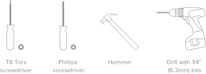
Collect Tools
You will need the following tools to perform an installation:
Collect Additional Hardware for Installation
You will need the following hardware to perform an installation:
Installation Instructions
Warning: Due to the heat dissipation in the back of APs during normal operation, please do not stack powered on APs on top of each other during pre-installation to avoid heat damage.
Choose Your Mounting Location
A good mounting location is important to getting the best performance out of your MR42E access point. Keep the following in mind:
- The antenna attached to the access point should have unobstructed line of sight to most coverage areas. For example, if installing in an office filled with workspaces divided by mid-height cubicle walls, installing on the ceiling or high on a wall would be ideal.
- Power over Ethernet supports a maximum cable length of 300 ft (100 m).
- If being used in a mesh deployment, the MR42E should have line of sight to at least two other Meraki devices. A Cisco Partner can help ensure that your AP placement is ideal.
Install the MR42E
For most mounting scenarios, the MR42E mount cradle provides a quick, simple, and flexible means of mounting your device. The installation should be done in two steps. First, install the mount cradle to your selected location. Then, attach the MR42E to the mount cradle.
Attach the mount cradle
The MR42E mount cradle can be used to install your access point in a wide range of scenarios: wall or solid ceiling, below a drop ceiling, on various electrical junction boxes.
The mount cradle contains a variety of hole patterns that are customized for each installation scenario. The mounting template (included inbox with mount cradle) should be used to drill holes for wall mounts and also to identify the correct hole patterns in the mount cradle that should be used for each type of mount. The included mount cradle template shows the hole patterns that should be used for each type of mount.
Wall or Solid Ceiling Mount Using mount cradle
Using included wall anchors and screws, attach the mount cradle to your mounting wall or ceiling. It is recommended that the MR42E be mounted to a wall or solid ceiling using the mount cradle for physical security reasons.
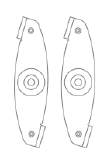
Drop ceiling mount using mount cradle
To mount your MR42E on a drop ceiling T-rail, use the included drop ceiling mounting accessory kit. The accessory kit can be used to mount to most 9/16”, 15/16” or 1 ½” T-rails. The kit contains:
- Drop ceiling mounting clips with set screws
- 6-32x4 mm screws

- 6-32x7 mm screws only used for recessed rail mount (uncommon)

- 2 rubber spacers

- Attach the T-rail clips to the T-rail by rotating them and snapping them into place as shown. The black foam pads should be compressed slightly after installation.
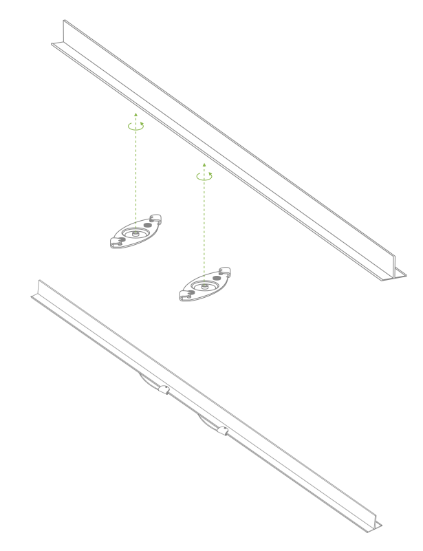
- Using the dashed lines on the mount cradle template as a guide, set the proper spacing of the T-rail clips on the T-rail.
- Tighten the set screws on the T-rail clips to secure the clips using a 5/64”(2 mm) hex key.
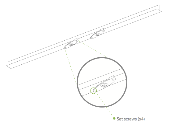
- Attach the mount cradle to the T-rail clips using the mount cradle holes (marked with a “T“).
Tip: Pre-assemble rubber spacers and screws to the mount cradle. The mount cradle can then be held with one hand while the other hand holds a screwdriver. If mounting your MR42E to a dropped ceiling, skip to the "Power the MR42E" section.
Electrical Junction Box Mount Using mount cradle
The MR42E can be mounted to a 4” square cable junction box, a 3.5 or 4” round cable junction box, or various U.S. and European outlet boxes (mounting screws are not included).
Using appropriate mounting hardware for your specific type of junction box, attach the mount cradle to the junction box.
Power the MR42E
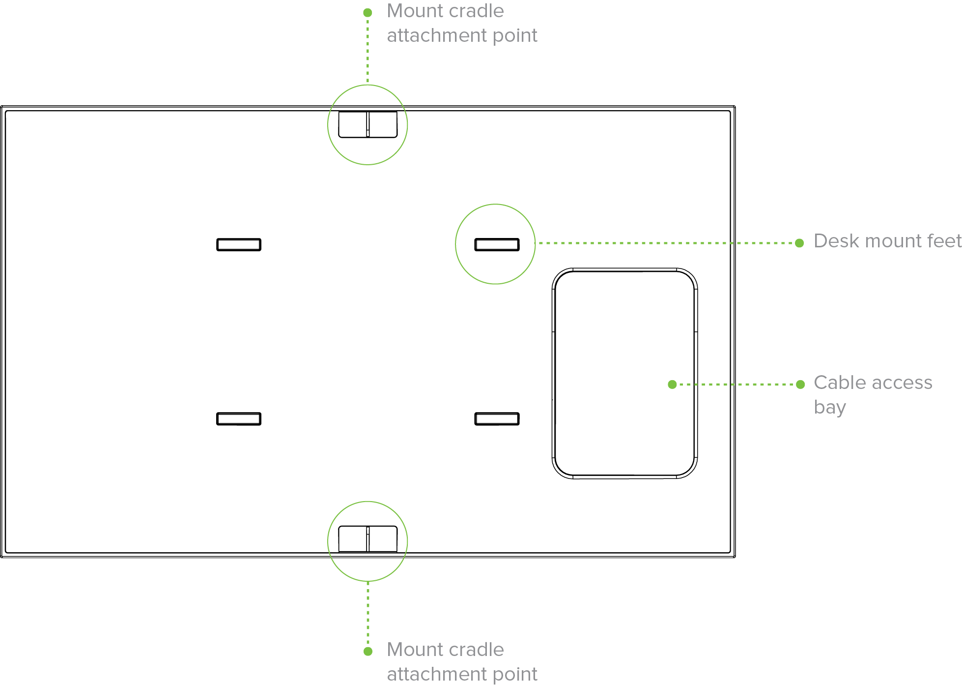
If mounting to an electrical junction box, feed the Ethernet cable through the cable access hole in the mount cradle. If mounting to a wall or ceiling, the Ethernet cable will feed from behind the MR42E. The "Power Source Options" section of this document lists the different powering options and their unique characteristics.
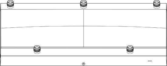
Mount the MR42E
Attach the MR42E to the Mount Cradle
(This section applies to wall and/or solid ceiling, drop ceiling or electrical junction box mount
where you have already installed the mount cradle.)
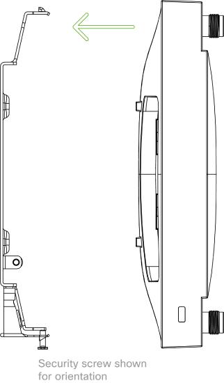
The MR42E attaches to the mount cradle with two tabs on the cradle that insert into the MR42E, and is secured to the cradle using one screw.
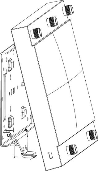
To attach the MR42E to the mount cradle properly, line up the top edge of the AP with the top tab of the mount cradle. Since the cradle is already mounted to the wall, guide the MR42E towards the top tab and insert the top tab into the MR42E’s slot.
Then adjust the MR42E to guide the MR42E’s bottom slot into the cradle’s bottom tab until it clicks into place. Once in place, the MR42E should be secured to the cradle by using one of the included screws in the cradle’s bottom tab.
To release the MR42E from the mount cradle, first remove the security screw that secures the MR42E to the cradle’s bottom tab. While holding the MR42E with one hand, press the cradle’s bottom tab upwards, releasing the MR42E from the bottom of the cradle. Then remove the MR42E from the cradle’s top tab.
Desk or Shelf Mount
The MR42E can be placed on a desk or shelf resting on the non-scratch rubber feet. The mount cradle is not necessary for a desk or shelf installation.
Attach Antenna
The MR42E is certified for use with the following Meraki indoor antennas:
- MA-ANT-3-A1/5 (1/5 stands for the quantity of the antennas)
- MA-ANT-3-B1/5 (1/5 stands for the quantity of the antennas)
- MA-ANT-3-C5 (5 stands for the number of ports for the antennas)
- MA-ANT-3-D5 (5 stands for the number of ports for the antennas)
- MA-ANT-3-E5 (5 stands for the number of ports for the antennas)
- MA-ANT-3-F5 (5 stands for the number of ports for the antennas)
These antennas come with RP-TNC connectors compatible with the MR42E.
Connecting MA-ANT-3-A/B series antennas
The MA-ANT-3-A/B series antennas are dipole omnidirectional antennas that may be connected to any of the antenna connectors on the MR42E, order is not important.
Connecting MA-ANT-3-C/D/E/F series antennas
The MA-ANT-3-C/D/E/F antennas will come with five antenna cables with RP-TNC connectors that connect into the five antenna ports on top of the access point. Four antenna cables have a white jacket just above the RP-TNC connector and should connect into the three 2.4/5 GHz antenna ports and one Scanning antenna port. One of the antenna cables will have a grey jacket above the RP-TNC connector and should connect into the IoT antenna port.
C/D/E/F series antennas will be automatically detected by the AP. Once an antenna is detected by the AP it cannot be changed in dashboard until the antenna is removed and AP is rebooted.
It is important to ensure that all five antenna ports on the MR42E are connected to their respective antenna cables for maximum performance and functionality.
Using Non-Meraki Antennas
Using MR devices with non-Meraki antennas is not recommended. If customers use non-Meraki antennas, it is important to connect one of the antennas to the scanning radio as the scanning radio cannot be turned off. Data captured on the scanning radio is used to feed information into the AutoRF algorithm, and if an antenna is not connected, AutoRF can yield undesirable results. Additionally, Meraki dashboard does not have information on any non-Meraki antennas and customers need to ensure that the correct TX power limits are set in order to maintain regulatory compliance.
Secure the MR42E
Depending on your mounting environment, you may want to secure the MR42E to its mount location. Your MR42E can be secured in several ways. If the MR42E has been installed using the mount cradle, it should be secured via security screw (Torx security screws are included) and/or Kensington lock. If the mount cradle was not used, the MR42E can still be secured using a Kensington lock.
Security Screw
Install the security screw in the lower mount cradle tab.
Kensington Lock
Attach a Kensington lock cable to the access point at the hard point on the side of the device.
Attach the other end of the cable to a secure location, such as a pipe or building fixture.
Verify Device Functionality and Test Network Coverage
- Check LEDs
- The Power LED should be solid green (or blue, if clients are connected). If it is flashing blue, the firmware is automatically upgrading and the LED should turn green when the upgrade is completed (normally within a few minutes). See the "LED Indicators" section for more details. .
- Note: Your MR42E must have an active route to the Internet to check and upgrade its firmware.
- Verify access point connectivity
- Use any 802.11 client device to connect to the MR42E and verify proper connectivity using the client’s web browser.
- Check network coverage
- Confirm that you have good signal strength throughout your coverage area. You can use the signal strength meter on a laptop, smart phone, or other wireless device.
Warranty
Additional warranty information can be found on the MR42E Datasheet or on the Warranty Returns (RMA) page of the Cisco Meraki website.
Troubleshooting
Reference the MR Product Page for additional information and troubleshooting tips.