
CW9166 Installation Guide
CW9166I Installation Guide
The Cisco Catalyst Wireless 9166I is a tri-band enterprise-class WiFi 6E cloud-managed access point supporting the 2.4 GHz, 5 GHz, and the newly opened unlicensed 6 GHz frequency bands. Designed for the ultra-high capacity and highest density, these AP meet the needs of the most demanding and mission-critical environments. The access point includes a fourth radio dedicated to optimizing the RF environment and securing the airwaves. The AP also has an additional Bluetooth Low Energy (BLE) capable radio used for location and other IoT applications. In addition, the CW9166 has a USB port.
About this Guide
This guide provides instructions on how to install and configure your CW9166I access points. This guide also provides mounting instructions and limited troubleshooting procedures. For more wireless installation guides, refer to the wireless installation guides section on our documentation website.
Product Overview
Physical Specifications
| CW9166 |
|
Interfaces
|
|
Power
Power over Ethernet injector and DC adapter sold separately Actual power consumption may vary depending on the AP usage USB will be disabled when powered by 802.3 at/PoE+ It is recommended that you ensure that LLDP is enabled to allow proper power negotiation |
|
Environment • Operating temperature: 32 °F to 122 °F (0 °C to 50 °C) • Storage and Transportation Temperature: -4 °F to 158 °F (-20 °C to 70 °C) • Humidity: 10 to 90% non-condensing |
|
Physical Security • Kensington lock hardpoint * Screws that can be attached to the security hasp of the universal mounting bracket • Concealed mount plate with anti-tamper cable bay |
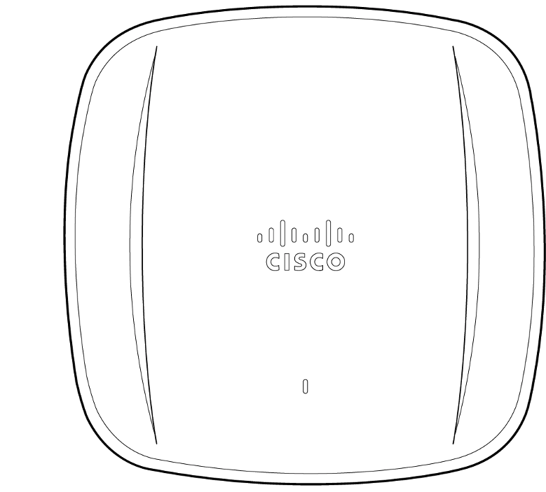
Product View and Physical Features
Your CW9166I has the following features:
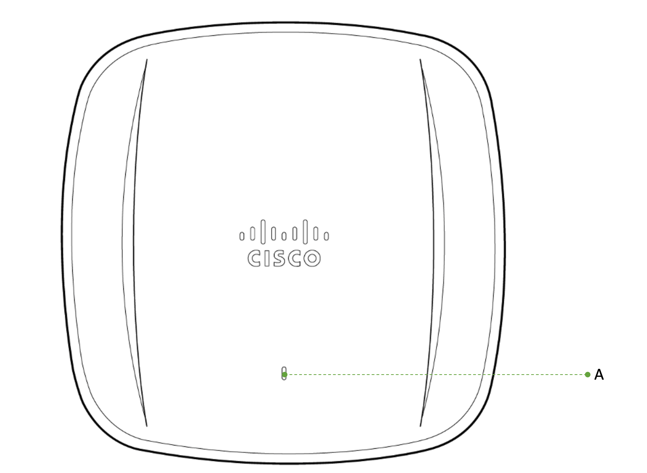
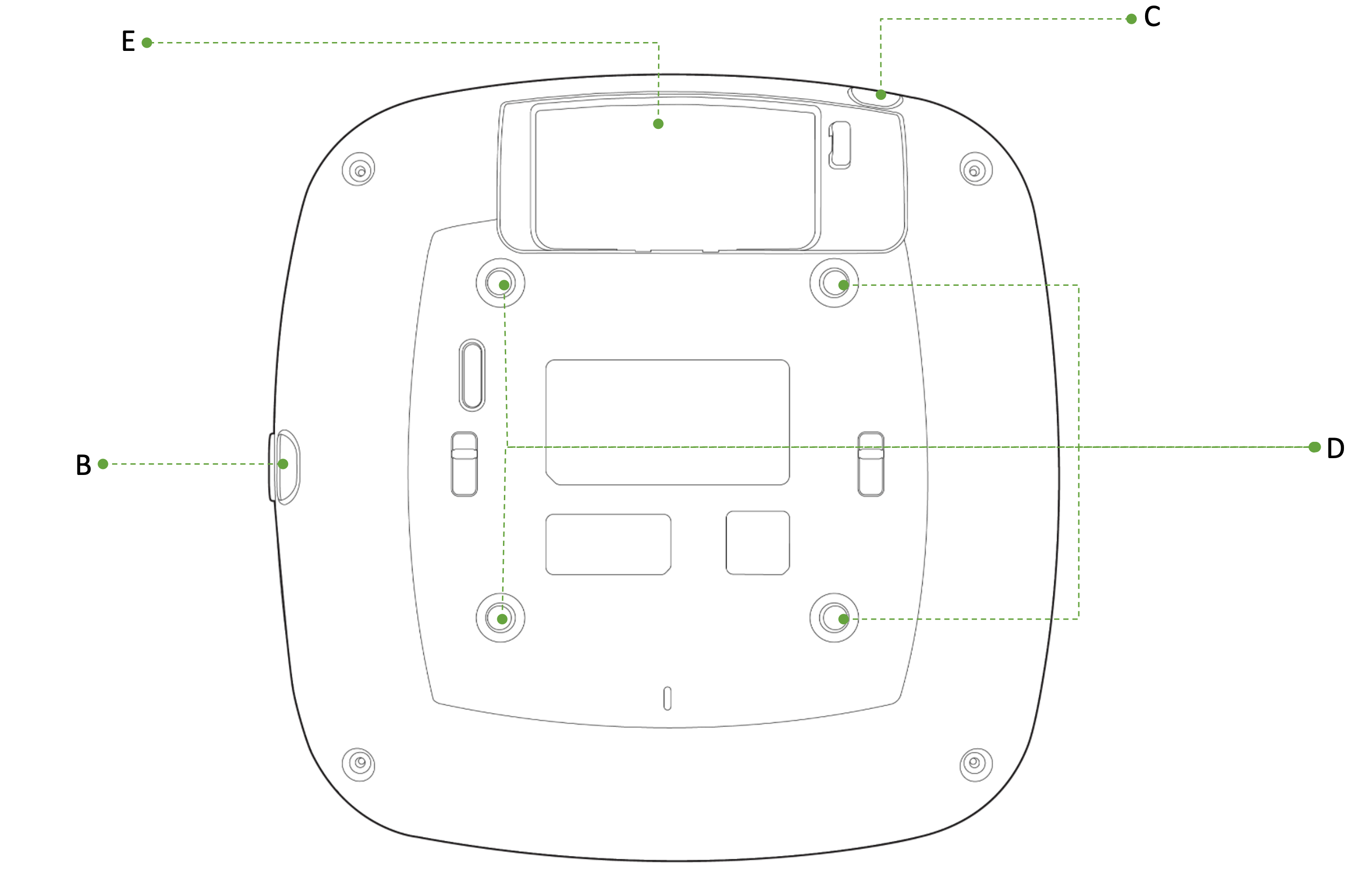
A - LED indicator
B - USB Slot - with protective cover
C - Kensington lock hard point
D - Rubber Feet/universal mounting bracket slide in points
E - Cable access bay
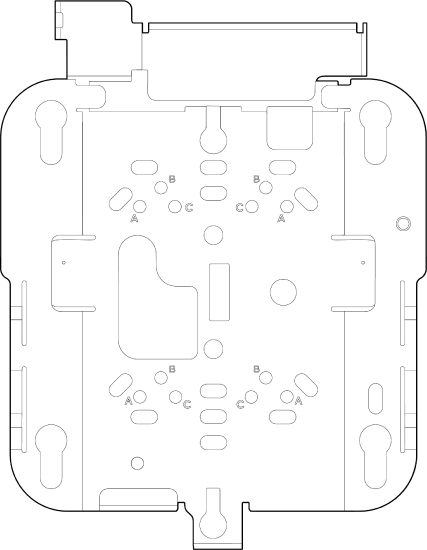
The Meraki AP comes with the default Cisco universal mounting bracket (AIR-AP-BRACKET-2) that has the following features:
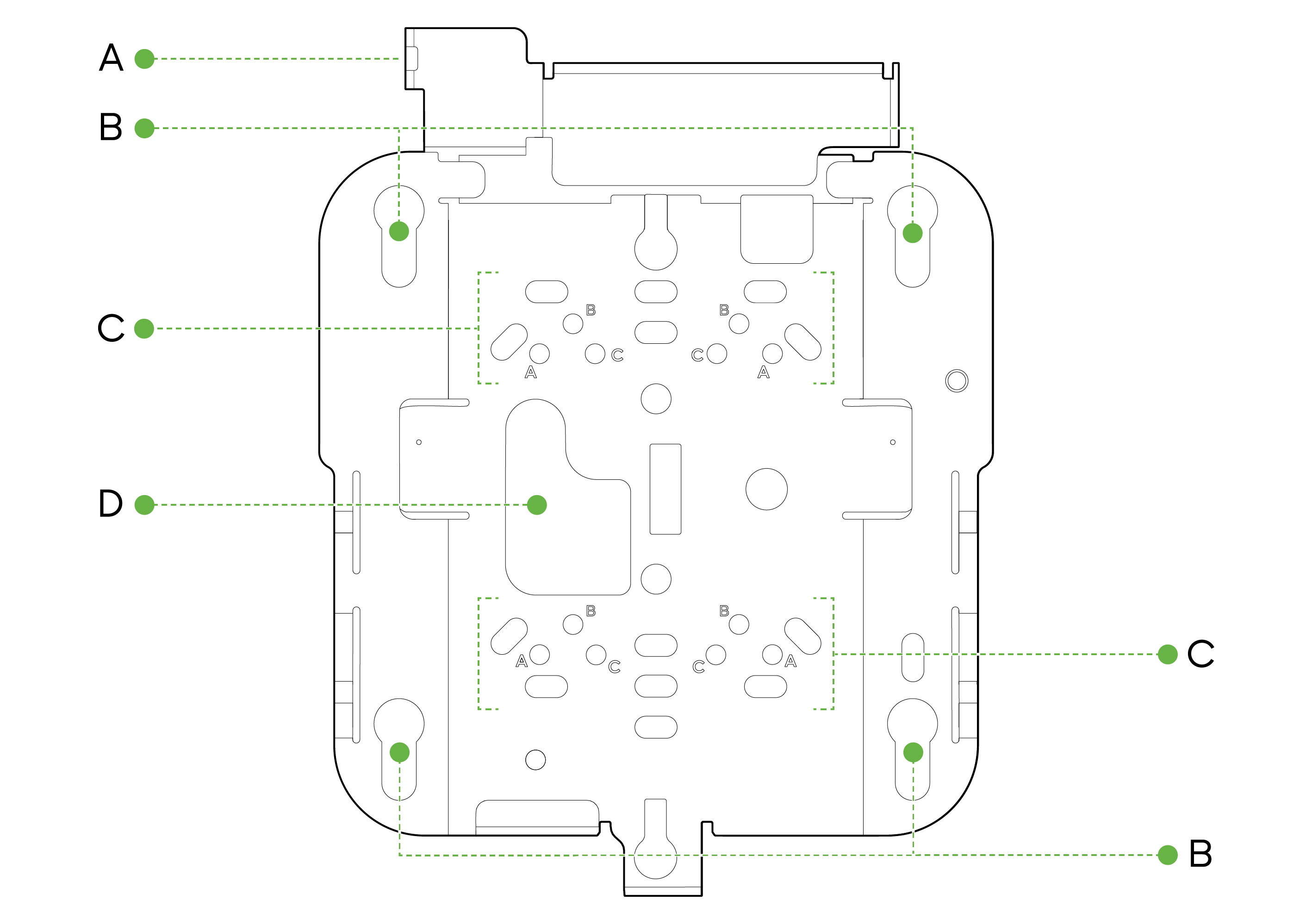
A - Security Hasp
B - Access Point Mounting Keyholes
C- T-rail attachment points
D - Cable access slot
Security Features
These AP feature multiple options for physically securing the access point after installation:
1. Security hasp – The universal mounting bracket has a security hasp and can be used to secure the access point to the universal mounting bracket. Engaging the security screw prevents accidental dislodging and theft.
2. Kensington lock – The access point contains a hard point that allows it to be secured to any nearby permanent structure using a standard Kensington lock.
Ethernet Ports
The CW9166I features one RJ45 port capable of operating at 100/1000/2.5G/5G BASE-T Ethernet (RJ45).
 5G, ϟ
5G, ϟ
The labeled “5G, ϟ” accepts 802.3at and 802.3bt power. This port is typically used as the primary uplink to your LAN/WAN.
Warning: AP does not support 802.3af as a power source
Power Source Options
These AP can be powered by a single M-Gig 802.3bt capable UPoE port, allowing for full operation including providing up to 4.5W of power to the USB port. The AP is capable of operating at its full capacity when powered by a single 802.3at power source, however, the USB port will be disabled.
The table below indicates the different modes of PoE power input and the expected operation of the AP
|
Port0 |
2.4GHz |
5GHz |
6GHz |
Scan |
IoT |
USB |
|
AT |
4x4 |
4x4 |
4x4 |
ON |
ON |
OFF |
|
BT |
4x4 |
4x4 |
4x4 |
ON |
ON |
ON |
CW9166I AP can be powered by PoE power in different modes as mentioned above when using a PoE capable switch. They can also be powered by a single 802.3bt capable PoE injector MA-INJ-6 Meraki multiGigabit 802.3bt Power over Ethernet Injector. It can also be powered by an AC power adaptor MA-PWR-50WAC - Meraki AC Adapter for MR Series
Factory Reset Button
If the button is pressed and held for at least five seconds and then released, the AP will reboot and be restored to its original factory settings by deleting all configuration information stored on the unit.
LED Indicators and Run Dark Mode
Your access point is equipped with a multi-color LED light on the front of the unit to convey information about system functionality and performance:
• Orange - AP is booting (permanent Orange suggests hardware issue)
• Rainbow - AP is initializing/scanning
• Blinking Blue - AP is upgrading
• Green - AP in Gateway mode with no clients
• Blue - AP in Gateway mode with clients
• Blinking Orange - AP can't find uplink
NOTE: NOTE: Blinking Green LED indicates that the device is in site survey mode. Please see the Conducting Site Surveys with MR Access Points for more details.
The CW9166 access point may be operated in the “Run Dark” mode for additional security and to reduce the visibility of the access point. In this mode, the LED will not be illuminated. This mode may be enabled through the Meraki Dashboard.
Package Contents
The access point packages contain the following:
CW9166I Cloud-Managed Access Point
Cisco Universal Mount Bracket - AIR-AP-BRACKET-2
T-Rail mount attachment (AIR-AP-T-RAIL-R) and screws (5 Nos - 6-32 x 1/4 included)
 x5
x5
Safety and Warnings
These operations are to be taken with respect to all local laws. Please take the following into consideration for safe operation:
• Power off the unit before you begin. Read the installation instructions before connecting the system to the power source.
• Before you work on any equipment, be aware of the hazards involved with electrical circuitry and be familiar with standard practices for preventing accidents.
• Read the wall-mounting instructions carefully before beginning installation. Failure to use the correct hardware or to follow the correct procedures could result in a hazardous situation to people and damage to the system.
• This product relies on the building’s installation for short-circuit (overcurrent) protection. Ensure that the protective device is rated not greater than 15 A, 125 Vac, or 10A, 240 Vac.
• Please only power the device with the provided power cables or standard PoE to ensure regulatory compliance.
Pre-install Preparation
You should complete the following steps before going on-site to perform an installation.
Configure your Dashboard Network
The following is a brief overview only of the steps required to add an access point to your network. For detailed instructions about creating, configuring, and managing Meraki wireless networks, refer to the online documentation (documentation.meraki.com).
1. Log in to http://dashboard.meraki.com. If this is your first time, create a new account.
2. Find the network to which you plan to add your APs or create a new network.
3. Add your APs to your network. You will need your Meraki order number (found on your invoice) or the serial number of each AP, which looks like Qxxx-xxxx-xxxx, and is found on the bottom of the unit. You will also need your license key, which you should have received via email.
4. Go to the map / floor plan view and place each AP on the map by clicking and dragging it to the location where you plan to mount it.
Check and Set Firmware
To ensure your access point performs optimally immediately following installation, it is recommended that you facilitate a firmware upgrade prior to mounting your AP.
1. Attach your AP to power and a wired Internet connection. See the "Getting Power to the AP" section for details.
2. The AP will turn on and the LED will glow solid orange. If the unit does not require a firmware upgrade, the LED will turn either green (no clients associated) or blue (clients associated) within thirty seconds.
* If the unit requires an upgrade, the LED will begin blinking orange until the upgrade is complete, at which point the LED will turn solid green or blue. You should allow at least a few minutes for the firmware upgrade to complete, depending on the speed of your internet connection.
Check and Configure Upstream Firewall Settings
CW9166 APs use device_to_cloud connectivity method and will require TCP port 443 to be open on any upstream firewalls. The most current list of outbound ports and IP addresses for your particular organization can be found on the firewall configuration page in your dashboard.
It is advisable to refrain from using a proxy server for 443 sessions as it could cause potential cloud connectivity issues and break the firmware upgrade process which could cause APs to be stuck on constant rebooting cycles.
Assigning an IP Address
All gateway APs (An AP with Ethernet connections to the LAN) must be assigned a routable IP address. These IP addresses can be dynamically assigned via DHCP or statically assigned.
Static Assignment
• Static IPs are assigned using the local web server on each AP. The following procedure describes how to set the static IP:
• Using a client machine (e.g., a laptop), connect to the AP wirelessly (by associating to any SSID broadcast by the AP) or over a wired connection.
• If using a wired connection, connect the client machine to the AP either through a PoE switch or a PoE Injector. If using a PoE switch, plug an Ethernet cable into the AP’s Ethernet jack, and the other end into a PoE switch. Then connect the client machine over Ethernet cable to the PoE switch. If using a PoE Injector, connect the AP to the “PoE” port of the Injector, and the client machine to the “LAN” port.
• Using a web browser on the client machine, access the AP’s built-in web server by browsing http://my.meraki.com. Alternatively, browse to http://10.128.128.128.
• Click on the “Uplink Configuration” tab. Log in. The default login is the serial number (e.g. Qxxx-xxxx-xxxx), with no password (e.g., Q2DD-551C-ZYW3).
• Configure the static IP address, netmask, gateway IP address, and DNS servers that this AP will use on its wired connection.
• If necessary, reconnect the AP to the LAN.
Static IP via DHCP Reservations
• Instead of associating to each Meraki AP individually to configure static IP addresses, an administrator can assign static IP addresses on the upstream DHCP server. Through “DHCP reservations,” IP addresses are “reserved” for the MAC addresses of the Meraki APs. Please consult the documentation for the DHCP server to configure DHCP reservations.
Collect Tools
You will need the following tools to perform an installation:
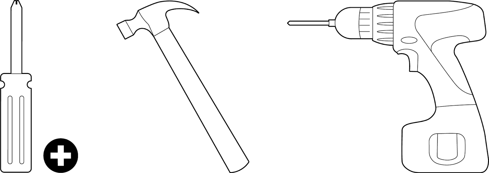
Phillips screwdriver, Hammer (optional), Drill with 1/4" (6.3mm) bits (optional) - depending on install type
Collect Additional Hardware for Installation
You will need the following hardware to perform an installation:
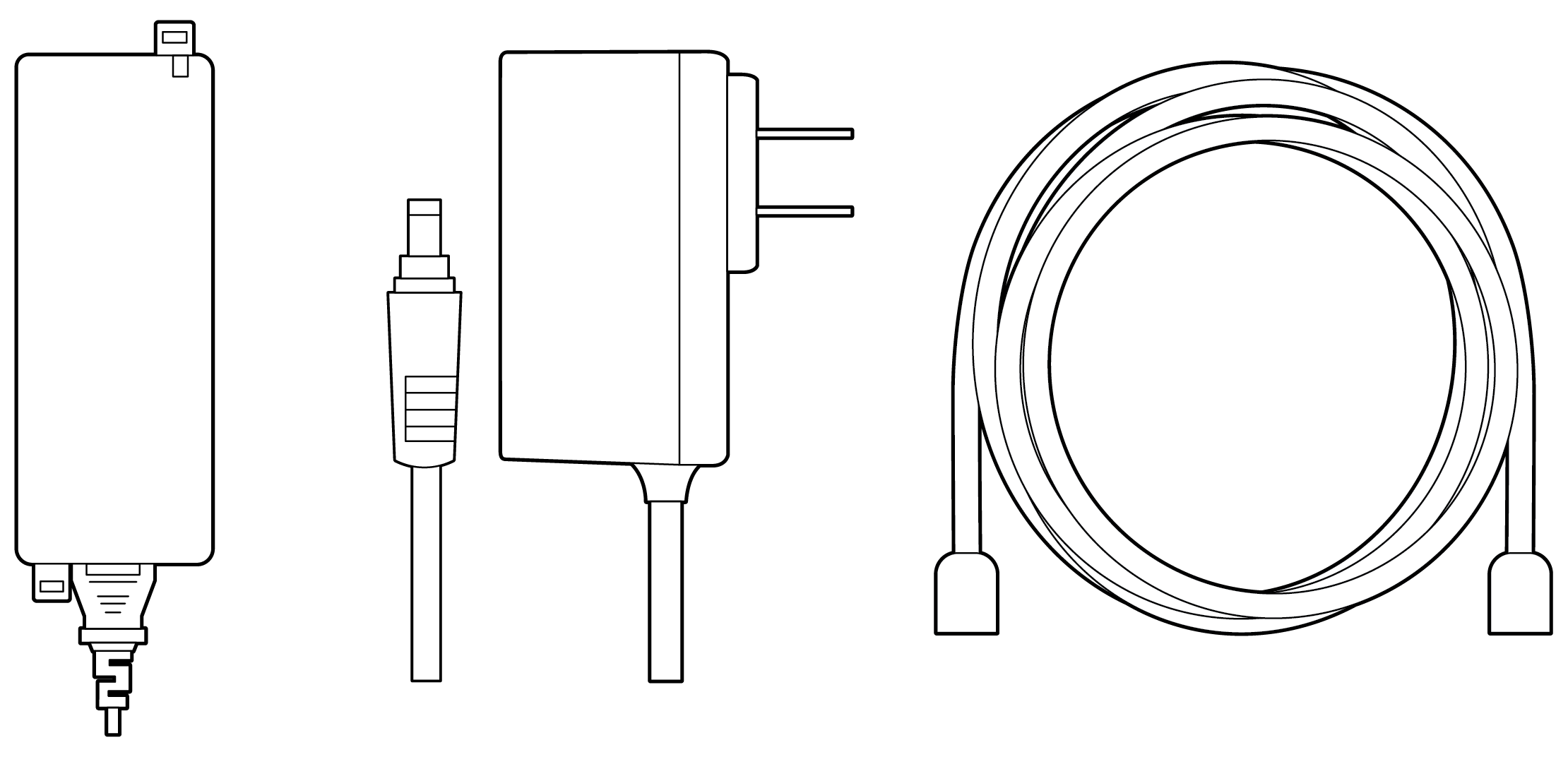
802.3bt/at PoE Power Source (either PoE switch or Meraki 802.3bt/at PoE Injector) or an AC adaptor and network cables with RJ45 connectors long enough for your particular mounting location
Note: CW9166I does not support 802.3af power source.
Note: CW9166I can be powered by a PoE Switch, PoE Injector or an AC adaptor. Powering up the AP with an AC adapter while connecting to a PoE source is not recommended. Proper functionality of the AP is not guaranteed and this can potentially cause damage to the AP hardware
Installation Instructions
Choose Your Mounting Location
A good mounting location is important to get the best performance out of your access point. Keep the following in mind:
1. The device should have an unobstructed line of sight to most coverage areas. For example, if installing in an office filled with workspaces divided by mid-height cubicle walls, installing on the ceiling or high on a wall would be ideal.
2. Power over Ethernet supports a maximum cable length of 300 ft (100 m).
3. If being used in a mesh deployment, the AP should have a line of sight to at least two other Meraki devices. A Cisco Partner and/or site survey can help ensure that your AP placement is ideal.
Install the AP
For most mounting scenarios, the access point universal mounting bracket provides a quick, simple, and flexible means of mounting your device. The installation should be done in two steps. First, install the universal mounting bracket to your selected location. Then, attach the AP to the universal mounting bracket.
Attaching the Universal Mounting Bracket
The access point universal mounting bracket (AIR-AP-BRACKET-2 - included) can be used to install your access point in a wide range of scenarios including a wall or solid ceiling, below a drop ceiling, or on various electrical junction boxes.
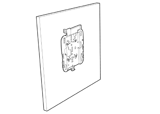
Wall or Solid Ceiling Mount Using Universal Mounting Bracket
Using included wall anchors and screws, attach the universal mounting bracket to your mounting wall or ceiling. It is recommended that the AP be mounted to a wall or solid ceiling using the universal mounting bracket for physical security reasons.
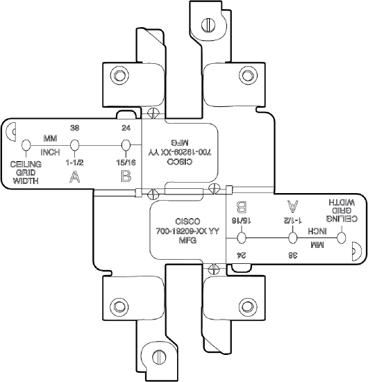
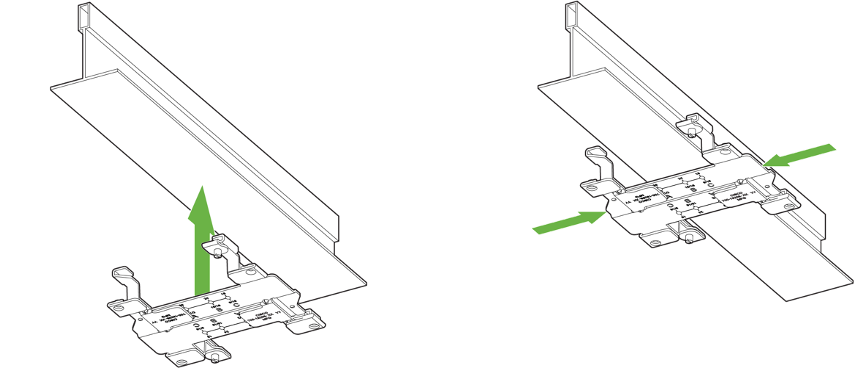
Drop Ceiling Mount using T-Rail Mount attachment
To mount your AP on a drop ceiling T-rail (AIR-AP-T-RAIL-R - included), use the included T-Rail mount attachment. The T-Rail mount attachment can be used to mount to most 9/16”, 15/16” or 1 ½” T-rails.
1. Place the ceiling grid clip over the T-rail and close it to the appropriate detent (A, B, or C).
2. Use a screwdriver to tighten the two ceiling grid clip locking screws to prevent the clip from sliding along the T-rail.
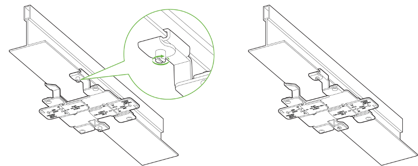
3. Observe the ceiling grid clip width detent letter (A, B, or C) that corresponds to the T-rail width.
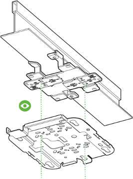
4. Align the corresponding holes (A, B, or C) on the mounting bracket over the mounting holes on the ceiling grid clip.
5. Hold the mounting bracket and insert a 6-32 x 1/4 in. screw into each of the four corresponding holes (A, B, or C) and tighten.

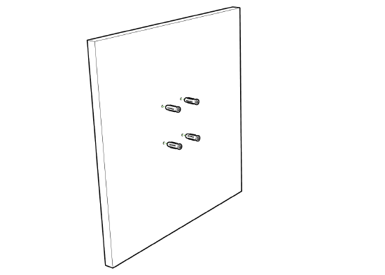
Wall Mount the AP using Universal Mounting Bracket
To mount the AP on the wall first, identify the location of the wall
1. Use the mounting bracket as a template to mark the locations of the mounting holes on the bracket
2. Use a 0.1360-in. [3.4772 mm] bit to drill a pilot hole at the mounting hole locations you marked.
3. Locate the pilot holes and then insert a fastener(not included) into each mounting hole and tighten.
4. Place the universal mounting bracket over the faster holes and then use screws up to 6 mm in diameter and at least 1 - 1/4 inch length (not included) to tighten it flush to the wall
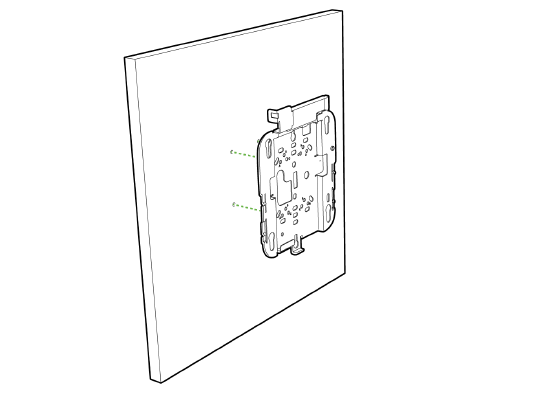
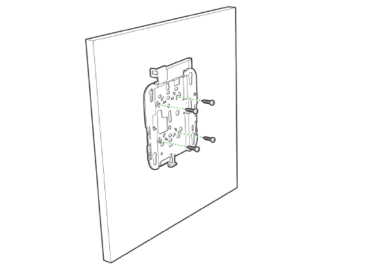
The AP is now ready to be mounted on the wall
Electrical Junction Box Mount Using Universal Mounting Bracket
The access point can be mounted to a 4” square cable junction box, a 3.5 or 4” round cable junction box, or various U.S. and European outlet boxes (mounting screws are not included).
Using appropriate mounting hardware for your specific type of junction box, attach the universal mounting bracket to the junction box.
Getting Power to the AP
If mounting to an electrical junction box, feed the Ethernet cable through the cable access hole in the universal mounting bracket. If mounting to a wall or ceiling, the Ethernet cable will feed from behind the AP. The "Power Source Options" section of this document lists the different powering options and their unique characteristics.
Mount the AP
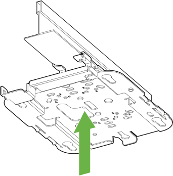
Attach the AP to the Universal Mounting Bracket
(Picture for Wall mount section and Picture for ceiling mount section )
The AP has four rubber feet that when gently slid in attach to the universal mounting bracket
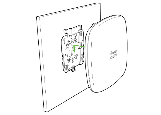
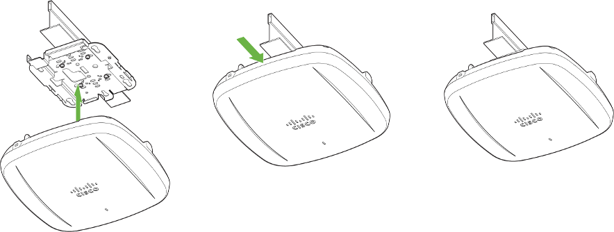
To attach the AP to the universal mounting bracket properly, align the access point feet over the keyhole mounting slots on the mounting bracket. Since the cradle is already mounted to the wall, gently guide the AP towards the mounting cradle until it clicks into place.
Physical Security
Depending on your mounting environment, you may want to secure the AP to its mount location. The access point can both be secured in several ways. If the AP has been installed using the universal mounting bracket, it should be secured via a security screw and/or Kensington lock. If the universal mounting bracket was not used, the AP can still be secured using a Kensington lock.
Kensington Lock
The access point contains a hard point that allows it to be secured to any nearby permanent structure using a standard Kensington lock. Attach a Kensington lock cable to the access point at the hardpoint on the side of the device. Attach the other end of the cable to a secure location, such as a pipe or building fixture.
Verify Device Functionality and Test Network Coverage
- Check LED
- The Power LED should be solid green (or blue, if clients are connected).
- If it is flashing blue, the firmware is automatically upgrading and the LED should turn green when the upgrade is completed (normally within a few minutes). See the "LED Indicators" section for more details.
Your AP must have an active route to the Internet to check and upgrade its firmware.
- Verify access point connectivity
- Use any 802.11 client device to connect to the AP and verify proper connectivity using the client’s web browser.
- Check network coverage
- Confirm that you have good signal strength throughout your coverage area. You can use the signal strength meter on a laptop, smartphone, or another wireless device.
Third Radio and 6 GHz Operation
The CW9166I has three client-serving Wi-Fi radios capable of operating in 2.4 GHz, 5 GHz, and 6 GHz frequencies. On the CW9166I, the third Wi-Fi radio can be configured to operate either in the 5 GHz frequency band or 6 GHz frequency band.
The out-of-the-box setting of the CW9166I will have the second and third radio both operating in the 5 GHz frequency band (Dual 5 GHz mode).
Note: When the CW9166I is operating in Dual 5 GHz mode, the 5 GHz radio in slot 1 operates only in the UNII-1 and UNII-2 bands (channels 36 to 64), and the radio in slot 2 is locked to the UNII-2-Extended and UNII-3 bands (channels 100 to 165).
6 GHz Configuration
The 6 GHz frequency band for the CW9166I can be enabled from the RF Profile page in the dashboard
Wireless > Configure > Radio Settings > RF Profiles
Under RF Profiles, existing profiles can be modified or new profiles can be created.
Under RF Profiles, existing profiles can be modified or new profiles can be created. Then the profile can be edited under the Flex radio selection for CW9166I. Using the drop-down menu, the 6 GHz band can be chosen for that particular RF profile to support the tri-band operation for CW9166I.
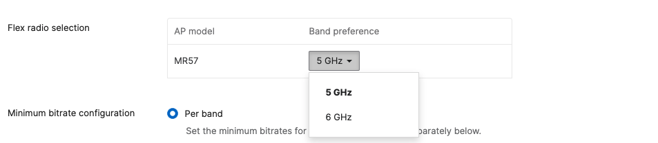
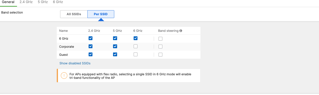
Once the 6 GHz band is enabled using the drop-down menu, 6 GHz capability can be enabled for all SSIDs
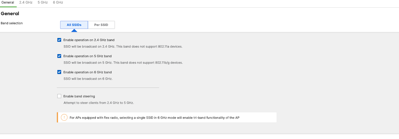
or an SSID that would require 6 GHz capability.
Preferred Scanning Channels
The 6 GHz frequency band introduces 59 20 MHz channels. Due to a large number of channels, the standard implements a new efficient process for clients to discover nearby access points. This is called Preferred Scanning Channels (PSC). PSCs are a set of 20-MHz channels that are spaced every 80 MHz. In order to support the PSC-based clients and effectively onboard the clients in the least possible time, the 6 GHz channel selection in the RF profile for CW9166I Auto RF configuration will be restricted to a set of PSC capable channels.
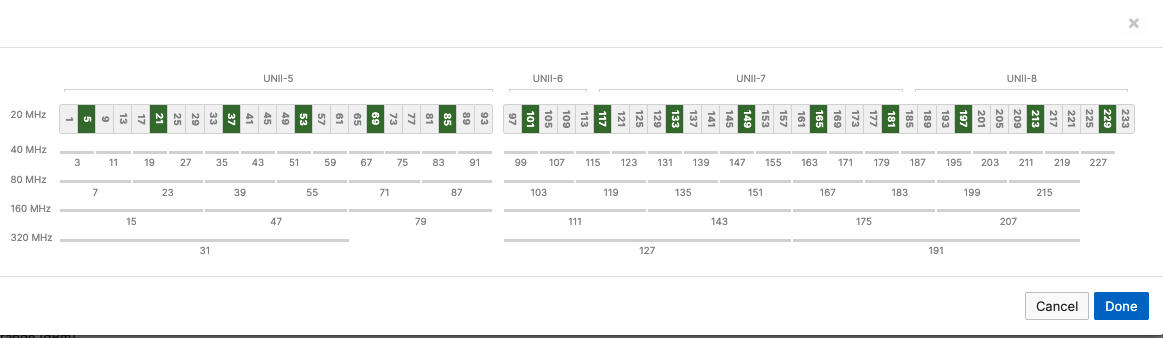
The list of the PSC channels is indicated above in green. Auto RF will choose a channel that is a PSC-supported channel for 20, 40, 80, and 160 MHz frequencies.
Note: When disabling a channel that is being used by Auto Channel configuration settings, the system will make sure to disable all 80 MHz of the closest PSC channel.
Warning: Please make sure to assign a PSC-supported channel when allocating a channel manually. There could be a substantial delay in the client connecting to the Access Point if a non-PSC supported channel is selected during manual allocation
WPA3 Support
WiFi 6E in the 6 GHz frequency band requires the clients to support WPA3 as a mandatory mode of operation. WPA2-WPA3 transition mode is not supported in the 6 GHz frequency. If an SSID is configured to operate across all three frequency bands, then the SSID should be configured to be WPA3 only
Note: If an SSID is configured to support WPA3 transition mode across all three frequency bands, then the 2.4 GHz and the 5 GHz frequency will broadcast the SSID with transition mode support. The SSID will not be broadcasted in the 6 GHz mode.
Basic Troubleshooting
The following steps can be used for troubleshooting basic connectivity issues with your access point.
• Ensure nothing is plugged into the access point's console port.
• Reset the access point
• Factory reset the access point by holding the factory reset button for 5 seconds
• Try switching cables, or testing your cable on another device
If your access point still does not connect, the following instructions may be useful, depending on your issue.
Check Ethernet Port Functionality by Connecting to the AP
1. Disable the Wireless adapter on your computer.
2. Make sure the Ethernet adapter on your device is set to obtain an IP address automatically via DHCP.
3. Connect your computer to the Ethernet port on the AP with an Ethernet cable.
4. The Ethernet LED on the AP should turn solid green or blue.
5. If the Ethernet LED does not turn solid green or blue, try swapping the cable. If the Ethernet port still does not turn green or blue, try the second Ethernet port, if the AP has one.
6. If the Ethernet LED does not turn solid green or blue, you may have a bad port on the AP. If this is the case, the AP signal LEDs will continue to scan.
7. Once the Ethernet LED turns solid green or blue, your computer should obtain an IP address from the AP via DHCP.
Check Static IP Address Configuration
1. If the AP has a static IP address, the green signal LEDs will begin to flash on and off and you will not receive an IP address via DHCP.
2. Disconnect the Ethernet cable from the AP.
3. Associate to the SSID being broadcasted by the AP. If there are no other APs in the network within range the SSID may be appended with "-scanning".
4. Go to my.meraki.com in your web browser.
5. The MAC address on the back of the access point should match the physical address value on the my.meraki.com Overview page.
6. Once you have verified that the MAC address is correct on the overview tab, click the tab Static IP configuration.
7. Enter the username (serial number on the back of the AP) which is case sensitive and must include the dashes. (There is no password).
8. Make sure your AP is set to obtain a correct DHCP or static IP address configuration from your network.
Reference https://documentation.meraki.com/MR for additional information and troubleshooting tips.
If you are still experiencing hardware issues, please contact Cisco Meraki support by logging in to the Dashboard and using the Help option near the top of the page, then opening an email case or calling using the contact information on that page.
Warranty
Additional warranty information can be found on the CW9166 Datasheet or on the Warranty Returns (RMA) page of the Cisco Meraki website.
If your Cisco Meraki device fails and the problem cannot be resolved by troubleshooting, contact support to address the issue. Once support determines that the device is in a failed state, they can process an RMA and send out a replacement device free of charge. In most circumstances, the RMA will include a pre-paid shipping label so the faulty equipment can be returned.
In order to initiate a hardware replacement for non-functioning hardware that is under warranty, you must have access to the original packaging the hardware was shipped in. The original hardware packaging includes device serial number and order information and may be required for return shipping.
Meraki CW9166I devices have been tested and found to comply with the limits for a Class B digital device, pursuant to part 15 of the FCC rules. These limits are designed to provide reasonable protection against harmful interference in a residential installation. This equipment generates, uses and can radiate radio frequency energy and, if not installed and used in accordance with the instructions, may cause harmful interference to radio communications. However, there is no guarantee that interference will not occur in a particular installation.
Support and Additional Information
If issues are encountered with device installation or additional help is required, contact Meraki Support by logging in to dashboard.meraki.com and opening a case by visiting the Get Help section.
• The equipment is intended for industrial or other commercial activities.
• The equipment is used in areas without exposure to harmful and dangerous production factors unless otherwise specified in the operational documentation and/or on the equipment labeling.
• The equipment is not for domestic use. The equipment is intended for operation without the constant presence of maintenance personnel.
• The equipment is subject to installation and maintenance by specialists with the appropriate qualifications, sufficient specialized knowledge, and skills.
• Rules and conditions for the sale of equipment are determined by the terms of contracts concluded by Cisco or authorized Cisco partners with equipment buyers.
• Disposal of a technical device at the end of its service life should be carried out in accordance with the requirements of all state regulations and laws.
• Do not throw in the device with household waste. The technical equipment is subject to storage and disposal in accordance with the organization's disposal procedure.
• The equipment should be stored in its original packaging in a room protected from atmospheric precipitation. The permissible temperature and humidity ranges during storage are specified in the Operation (Installation) Manual.
• Transportation of equipment should be carried out in the original packaging in covered vehicles by any means of transport. The temperature and humidity during transportation must comply with the permissible established ranges of temperature and humidity during storage (in the off state) specified in the Operation Manual (Installation)
For additional information on Meraki hardware and for other installation guides, please refer to documentation.meraki.com.