
Location Analytics
Introduction
With the rapid adoption of mobile devices, many organizations can now leverage data to better understand foot traffic patterns and behavior in a brick-and-mortar environment. This location information, based predominantly on 802.11 wireless and bluetooth standards, can be used to engage users and optimize marketing strategies. For retail, this can help combat trends such as the erosion of in-store sales to online retailers, who for years have had access to similar data via the analytics produced by online tools (e.g., click-through conversion rates from online advertising).
Smartphones with WiFi can now be used as an indicator of customer presence thanks to a WiFi mechanism that is common across all such devices: probe requests. These 802.11 management frames are transmitted at regular intervals from WiFi devices. The frames contain information that can be used to identify presence, time spent, and repeat visits within range of a WiFi access point. These devices can be detected by WiFi access points irrespective of its WiFi association state meaning that even if a user does not connect his or her device to the wireless network, the device's presence can still be detected while the device is within range of the network and the device's WiFi antenna is turned on1.
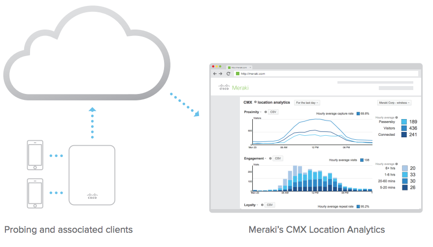
Since smartphones now have greater than 50% penetration across the general population2, probe requests can be used to build and detect a statistically significant data set regarding the presence of WiFi enabled devices within range of a given access point. Meraki wireless Access Points and cloud infrastructure gathers this data and presents it in aggregate on the Meraki Dashboard. This is done through intuitive and customizable graphs that can be used to understand trends such as capture rate (passersby vs. visitors), user engagement (total time spent), and visitor loyalty (new vs. repeat visits). Meraki is able to provide these analytics to all organizations by leveraging the industry-leading cloud architecture that is behind all Cisco Meraki products. Additionally, Meraki Scanning API is capable of exporting raw data from the observed probe requests, which organizations can use to integrate directly with third-party data warehousing or analytics platforms. Not only can this facilitate a deeper integration with traditional customer relationship management (CRM) platforms, but, due to its real-time nature, it opens doors to next-generation customer engagement initiatives.
Viewed holistically, Meraki's built-in location analytics views and real-time location API complement the existing traffic analytics functionality and complete a 360-degree understanding of devices on- and within range of a Cisco Meraki network. This whitepaper explores Cisco Meraki's location functionality and offers insights into the technology behind these features and some of the use-cases that it can enable. These features are part of Cisco Meraki's MR series wireless access points.
1 The collection and use of location information has raised general privacy concerns. Meraki is sensitive to these issues and has designed location analytics with privacy in mind. Users concerned with having the presence of their device detected by these kinds of systems can avoid detection simply by turning off the WiFi antenna on the device.
Location Data Collection
Cisco Meraki Access Points generate a presence signature from any WiFi-enabled device by detecting probe requests and 802.11 data frames, whether or not the device is associated to the network3. WiFi devices typically emit a probe request at regular intervals based on the device state (see Table 1). Smartphones send probe requests to discover surrounding wireless networks, so that they can make the networks available to the user.
| Device State | Probe Request Interval (smartphones) |
| Asleep (screen off) | ~ once a minute |
| Standby (screen on) | 10 - 15 times per minute |
| Associated | varies, could require user to manually search for networks |
Table 1
Probe request interval seen on smartphone OS vendors (iOS, Android, others) - varies greatly based on apps, device upgrades, and other factors4.
Data frames received from all connected WiFi devices and probe requests detected from all devices seen within range (typically up to 100 feet or more) generate "seen device" events on Meraki Access Points. Triple-radio APs have a dedicated scanning radio that listens for probe requests 24x7 on all channels. Dual-radio APs lacking the scanning radio can hear probe requests when WiFi devices probe across all channels. Seen device information is uploaded through the secure management tunnel between the access point and the Meraki cloud.
Meraki's secure management tunnel is highly optimized for sending and receiving configuration statistics and high volumes of information, and the added overhead from seen device data is close to negligible; the total bandwidth consumed by the management tunnel remains around 1 kbit/s.
Meraki Access Points also detect the signal strength of data frames and probe requests, which can be used to estimate the physical position of the WiFi devices.
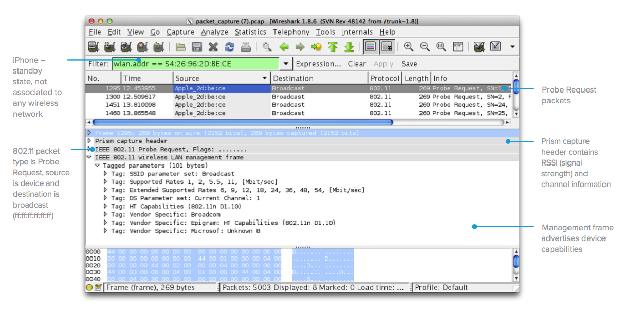
Figure 1: Typical probe request from an iOS device - 60 second packet capture taken from Meraki AP, opened using Wireshark.
3 Location data is largely captured per device using that device's media access control (MAC) address as a unique identifier. As part of a privacy technique, iOS, and Android operating systems have added functionality that attempts to randomize the WLAN MAC address a device uses, making it more difficult to track by solutions such as Meraki Location Analytics. As the number of mobile devices that implement randomization increases, solutions to detect and locate devices have changed. Meraki provides additional capabilities such as bluetooth information via the Meraki Scanning API, enabling Meraki customers to anonymously include wearable devices as part of their location analytics dataset.
4 Based on empirical evidence from Meraki's own experiments and those of our analytics partners. This behavior tends to vary greatly based on the operating system and which apps are installed on the phone for example, if a certain app is very active, it could cause a device that is asleep to probe several times a minute.
Data Aggregation and Display
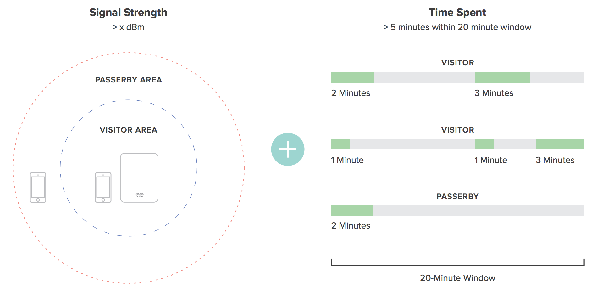
Once received by the Meraki cloud, presence signatures from all of the APs in a network are aggregated. After aggregation, data from each observed client device undergoes a series of computations to categorize it for later presentation. For example, retailers need to understand capture rate, which is the ratio of people passing by the store versus actually coming inside. To determine capture rate, the Meraki cloud analyzes the signal strength of each client device, along with the time spent within that location (a high signal strength on its own may not indicate a visitor if they are simply passing by the storefront quickly).
There are a number of different client states that are created and stored in Cisco Meraki's databases, computed using a variety of techniques. The list of categories and the underlying logic is shown in Table 2.
| Parameter | Definition | Computation |
| Capture Rate | Percentage of passersby who become visitors. A passerby is any device that was seen, while a visitor is a device seen for more than a certain time with high signal strength. This graph shows all devices that were seen, and whether they were considered a passerby or a visitor. The ratio of visitors to total clients seen denotes the capture rate percentage. |
1. Classifying passersby: any device seen at least once 2. Classifying visitors: a device is seen for more than five minutes in a twenty minute period. An RSSI of 15 or more opens up a session, and an RSSI of 10 or more maintains it |
| Engagement | A value in minutes showing the amount of time visitors spent within the range of the wireless network. | Viewing timestamps of presence signatures from clients to compute how long someone was within the wireless network range. |
| Loyalty | Percentage of new vs. repeat visitors. | An additional database entry per visitor detects number of repeat visits for a given time period. For example, if a client is seen 4 times within a month, they would be classified as a weekly visitor. At least 5 visits within 8 days would classify them as a daily visitor. |
4 RSSI - 95 = signal strength in dBm
Location Analytics
Location Analytics are available for dashboard users with organization-wide access, and can be found in the Meraki dashboard under Organization > Location Analytics.
If the data is not displayed for a given network even after 24 hours, verify that Analytics is enabled by navigating to Network-wide > Configure > General > Location and scanning > Analytics.
While the Meraki cloud runs the above computations in real time to calculate the various client states, the Meraki Dashboard displays it via intuitive graphs that visualize capture rate, engagement, and loyalty. These graphs can be toggled between simple and complex views. A calendar function allows the user to zoom in or -out of a given time period to see views as granular as one day (which can show how foot traffic varies and peaks during a certain day) or as wide as several months (which can show seasonal fluctuations).
A time calendar function is available to let you select specific time periods for viewing; this lets you adjust the x-axis of the above graphs to view the data for a specific time period, e.g. how the number of visitors changed over the course of a specific day or week. In order to see "hourly" data, you must look at the daily report or a time span of 3 days or less.
Note: Location analytics data has 1 year retention for daily analytics, 3 months retention for hourly analytics.
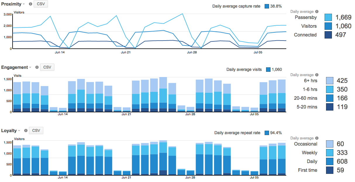
Proximity Graph
'Capture rate' is the % of passersby who become visitors.
'Visitors' are wireless devices that "visited" your network. A visit is initiated when a Meraki AP detects a probe with RSSI of 15 or greater. Visitors are devices which continue to send probes with RSSI of 10 or greater for 5 minutes within a 20 minute period. This 20 minute period begins when the AP receives the first probe with RSSI of 15 or greater.
'Passersby' are probing wireless devices detected by a Meraki AP, whose probes and dwell time did not meet the requirements to be considered a visitor. If clients are using randomization techniques, location analytics may be detecting falsified/anonymous client IDs, and this should be considered when analyzing location data.
With smartphone OS vendors (iOS, Android, others) implementing MAC randomization on client devices, we made a change in the way we calculate the Passerby devices in the Location Analytics tool to keep the data accurate. A unique non-randomized MAC address needs to be detected for more than 1 minute interval for the client device to be classified as Passerby. If the device is using MAC randomization the MAC address used for probe requests changes multiple times within the 1 minute interval. Dashboard will be eliminating these MAC addresses from the Location Analytics computation and the Scanning APIv2 output as well.
'Visitors' counted on the proximity graph are only counted once for their respective session. For example, if a device becomes classified as a visitor at 12 p.m., and maintains its session until 8 p.m., that device will only be counted as a 'visitor' for the 12 p.m. timeframe, along with an 'Engagement' value of 6+ hours. This allows for customers to determine how many visitors enter a location at a given time, and how long they stay.
Engagement Graph
A 'visitor' is a wireless devices that maintains high signal strength for longer than 5 minutes. This graph shows the amount of time visitors spent within range of the Wi-Fi network.
Loyalty Graph
This graph shows visitors based on how frequently they return. For example, a weekly visitor is someone who returned between 2 and 6 times in the last month
Filtering by Device Tags
The Location Analytics page offers additional reporting granularity through Device Tag filtering. This is particularly useful if administrators desire to review location analytics based on specific groupings of access points. For example, access points in Area A of a deployment could be tagged with "Area-A" and access points in Area B of a deployment could be tagged with "Area-B". The administrator would then be able to select either device tag to see location analytics data for that specific grouping of access points (or area in this scenario).
Clients are counted per tag but are deduplicated when looking at overall counts (not filtering by tag). For example, a client may be seen as a visitor on an access point with a tag of "Area-A" and may also be seen as a visitor on an access point with a tag of "Area-B" if the client had moved between areas. When filtering for either tag, the client will appear (counted once for each tag). However, when expanding the filter (from Devices by tag to All nodes), the per-tag client counts are deduplicated and the client is only counted once, not twice.
Running Comparisons
Cisco Meraki also has built a powerful comparative analysis tool that facilitates insights between networks within a given organization. By running a comparison, the Meraki Dashboard will overlay location data from the first data set on top of the second. Comparisons can be run to analyze different data sets, for example:
- Single site comparison between two different time periods (e.g., this week vs. last week)
- Multi-site comparisons between two different sites or sets of sites
- Between two different sites (site A vs. site B)
- Between one site and a batch of sites (site A vs. all sites, or site A vs. an average of sites A through D)
- Between two different batches of sites (all sites vs. average of sites A through D)
Comparative analysis of two different time periods is easily done by expanding the time scale that is shown on the Analytics Page.
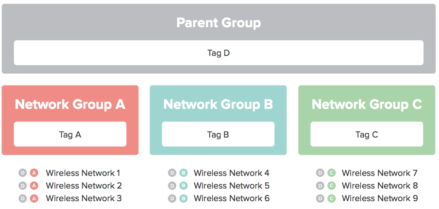
Comparing to batches of sites leverages Cisco Meraki's network tagging functionality, which allows administrators to create hierarchical network structures by assigning one or more tags to different networks. In this fashion, a large number of comparisons can be run in a multi-site organization based on the reporting that is required, e.g., 'show me how this site compares to the nationwide average within my organization, or 'show me how the sites in the organization's East region compare to the sites in its West region.
The recommended methods for deploying Cisco Meraki wireless networks remain unchanged as a result of the new location analytics. There is no need to change AP placement, orientation, or add more APs. The heuristics described in the above sections automatically take data from existing deployments to analyze and provide data on foot traffic.
There are a number of general guidelines and factors to keep in mind when deploying a Cisco Meraki network optimized for location analytics, including:
- Deploy physical access points as you normally would to provide wireless network coverage
- In the Meraki Dashboard, structure your deployment in an Organization/Network topology with one network per location. Since the Location Analytics data is computed and displayed on a per-network basis, you probably want to create a network per location (as opposed to all locations within a single network). The Dashboard interface is designed to facilitate the management of hundreds of networks.
- Tag different batches of networks on the Organization > Overview page. This lets you group sets of sites into batches, and the analytics data can be run in comparisons against tags.
- If your networks are in different time-zones, ensure that each network has its time-zone configured correctly on the Configure > Network-wide settings page so that consistent comparisons can be run.
- Allow time (several days) for Cisco Meraki's databases to populate with your network's information.
Value for Marketing and Business Intelligence Teams
The goal behind all of the data analytics and graphs presented is to provide a platform for both IT and non-IT departments to understand user presence. By understanding patterns such as foot traffic by time of day and how the capture rate varies across different sites, IT departments can gain a better understanding of network usage and trends, and non-IT departments, such as marketing and business intelligence teams, can gain insights and answer questions such as is my new marketing campaign at site A working based on the foot traffic numbers or do I need to staff more people at site B during peak hours. Some of the different use-cases for which Location Analytics could be useful are highlighted in the following table.
|
Use-Cases |
|
Location Heatmaps
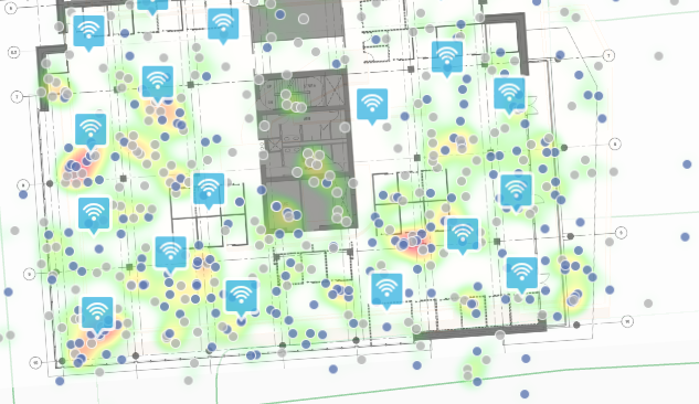
Part of Meraki's location capabilities include the ability to visualize where people are spending time inside a particular location over the course of the day (regardless of whether or not their devices are associated to the wireless network). This data is overlaid on a floor plan or Google maps, and can give network administrators and marketing/operations teams information on guest foot traffic flows within certain parts of a store or building. In order to attain the required level of location accuracy, the client probes should be heard by 3 or more APs to be overlaid on the floor plan.
The requirement for 3 or more APs in order to build a location heatmap is implemented starting firmware 26.1 onwards.
In areas where only APs without a dedicated scanning radio (e.g., MR28) are deployed, the location heatmap or the scanning API might not reliably report location information for WiFi clients. The location calculation in this scenario occurs if at least three nearby APs are on the same channel or if the APs perform active scans using the client-serving radio when no clients are associated.
Functions on heatmaps page
Floorplans can be toggled for views on different floors, along with the ability to remove the APs from the display or display different metrics on the APs (e.g. model number, current client count, historic client count, etc). The heatmap page includes a "playback" function - by pressing the play button, it is possible to see how the client density changes throughout the course of the day. Dates can also be toggled to see client density on a specific day in the past.
Underlying Metrics
The heatmaps are calculating using two metrics - (a) the number of devices were detected during the time period, and (b) how long those devices dwelled in the area. The colors represent the areas on the map where there is the most "presence." The intensity is based both on how many devices were detected during the time period and how long those devices dwelled in the area. Areas may be dark red either because there were lots of devices detected, or because there were a few devices that all stayed in the area for the entire hour.
Client Indicators
The heatmap will also plot the calculated location of clients within the wireless network. Grey circles are clients that are not associated to the wireless network that are just probing. Blue circles are clients that are connected to one of the SSIDs served by the wireless network.
Starting with MR 27.5, the location heatmap includes BLE clients. The heatmap displays BLE clients in a different color. The system aggregates their location data over time. Do not treat the displayed position as the client’s exact location at a specific moment.
More information on how to geoalign floor plans in Dashboard can be found in our article on using floor plans in Dashboard.
Location and Privacy
Meraki understands that some end users may be concerned about the collection and use of location information when enabling Location Analytics or the Scanning API. In an effort to address these concerns, Meraki developed location services with privacy in mind, including a number of security mechanisms to eliminate uniquely identifiable elements from the data that it collects. Meraki also recommends that its customers and partners implement a number of privacy-friendly features.
The following Dashboard features are disabled by default for Organizations that select the EU Cloud at the time of account setup:
- Location Analytics
- Location Heat Map
- Scanning API
Location and scanning services can be enabled under Network-wide > General > Location and scanning.
Hash Function
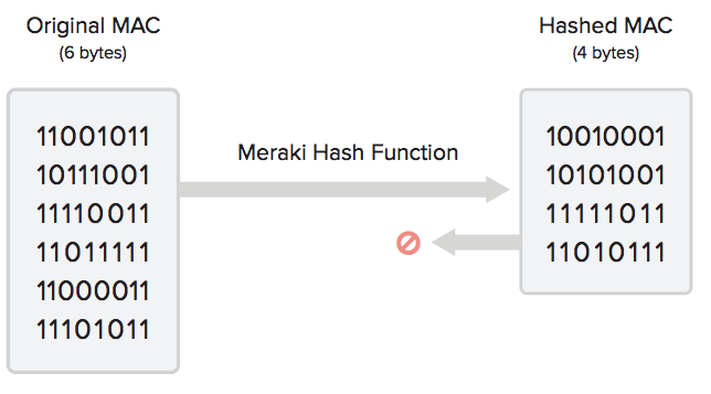
Meraki uses probe requests, data frames, and Bluetooth beacon frames to locate and store client location. Because the location data contain raw MAC addresses, Meraki implemented a number of security mechanisms to anonymize the data in an irreversible fashion. Using a unique Meraki algorithm, the Meraki cloud hashes, salts and truncates MAC addresses so that they are not identifiable. The Meraki cloud then stores only that hashed, salted and truncated version of the MAC address. This anonymization process is described in more detail below.
The hash function is as follows:
SHA1 is a widely known one-way cryptographic function. Using SHA1 hashes in this manner is the current industry standard. In order to provide an additional layer of security beyond SHA1 hashing, Meraki’s hash function truncates the hash to 4 bytes. This produces an information theoretic loss, as the domain of the function is larger than the range: a 6-byte MAC allows (2^48) possibilities whereas a 4-byte hash allows (2^32) possibilities. This results in 65,000 possible (org + MAC) combinations for each one 4-byte hashed MAC address. Therefore, given a MAC that has been salted, hashed, and truncated with the unique Meraki algorithm, it would be mathematically impossible to know with a reasonable degree of certainty what the original client MAC address was.
The hash function leads to information theoretic loss, and the original MAC address of client can never be recovered.
Cisco Meraki includes a customer-specific org-secret in the hash function. As a result, Cisco Meraki does not have any visibility into client behavior across our customers networks worldwide. And, of course, no Cisco Meraki customer can see the analytics of another customer’s organization or where foot traffic goes after leaving the presence of its own WiFi / BLE network.
Finally, Cisco Meraki’s website offers a global opt-out feature that allows users to submit the MAC addresses of their devices, after which the Meraki cloud will no longer detect their MAC addresses either for its built-in Location Analytics views or for real-time export via the Scanning API. Cisco Meraki also recommends that retailers and others using the Scanning API post notices on the availability of this global opt-out in prominent locations, preferably in the storefront or at building entrances where location detection is taking place.
Scanning API
Learn more with these free online training courses on the Meraki Learning Hub:
Introduction
Make sure to take a look at the updates for the Meraki Scanning API V3.
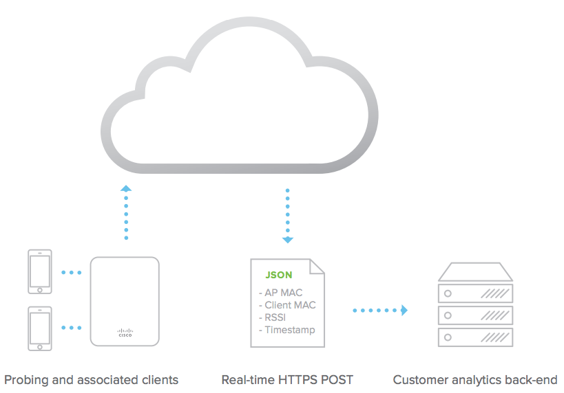
Using the physical placement of each access point on the Map & Floorplan of the Dashboard, the Meraki cloud aggregates raw client location data reported and provides a real-time estimate on the location of Wi-Fi (associated and non-associated) and Bluetooth Low Energy (BLE) devices in real-time. The Scanning API delivers this data to your real-time location application, data warehouse, or business intelligence systems.
Scanning API FAQ
What are the fundamental differences between V2 and V3 versions of the Scanning API?
There are a few key differences between the two versions,listed below:
-
Scanning API V3 uses a triangulation approach for computing location of the client devices. This requires the wireless client to be heard by 3 or more APs to have location information populated via the API output. In contrast, Scanning API V2 uses a “x/y/z” approach and only requires Z number of APs.
-
Scanning API V3 offers higher accuracy for location analytics compared to V2.
-
Scanning API V3 offers a better-organized data structure compared to V2, based on actual user feedback.
-
Scanning API V2 output excludes the MAC address of clients implementing MAC randomization. The MAC address used for probe requests changes multiple times within the 1-minute interval, not allowing Dashboard to determine if the client is a Passerby.
-
Randomized MAC addresses are accounted for API V3 location computation and output. This is possible as clients need to be connected with at least 3 APs in the same network to have its location triangulated.
-
With Scanning API V3, client information can be obtained with only one available AP in the network. However, location information requires the client to be detected by at least three nearby APs.
How much time delay should I expect in Scanning API output?
Typically Scanning API architecture is designed to send out location data every minute from Dashboard to the configured receiver but this depends on several factors. In practice, there could be 1 - 2 minute of delays due to these reasons (x/y/z), and users should be aware that this is not a real-time location service engine from Dashboard.
What are the requirements for enabling Scanning API V3?
Below are the requirements for Scanning API V3 to be configured in any wireless network:
-
All APs must run the current GA firmware (27.x) in order to leverage Scanning API V3 over WiFi and BLE.
Note: 802.11 wave2 and higher APs are supported with 27.x firmware version.
-
Have an receiver that is setup to receive and process the data sent out by the Scanning API V3.
What benefits do we get from Scanning API V3?
Scanning API V3 offers upgraded formatting of the API which is more user friendly and derived from extensive feedback received from partners and developers. Scanning API V3 also offers improved location accuracy along with more consistent data delivery.
What should I expect as we transition from V2 to V3 version of the Scanning API?
Scanning API V2 has no triangulation and uses a purely RSSI based model for location computation, this eliminates the need to have 3 or more APs that could receive the WiFi packets from the client device. Switching from V2 to V3, there may be a drop in clients with location information as some areas in the network might have fewer than 3 APs in the network that can receive the WiFi packets from the client device.
What will happen if I enable V3, but some physical locations don’t have at least three compatible APs?
In scenarios where the Scanning API V3 does not have at least 3 data points, no location information will be generated in the API output for a given wireless client. The API will provide the nearest AP MAC address based on the RSSI in the output. This can be used to get a rough estimate of the location of the wireless client device on the floor plan, but it is recommended to deploy at least three APs at any physical location that is upgrading to Scanning API V3
How do I ensure that the client is heard by 3 APs for Scanning API V3 to capture the location?
A well planned network with a predictive site survey of having tertiary coverage in all areas of interest should have no issues providing location information for all the clients in a given network. If a specific area is not generating location information in Scanning API V3 then it would be recommended to perform a site survey of the location and ensure that at least 3 APs are providing coverage throughout the floor plan.
Can we enable Scanning API V2 and V3 simultaneously for a given network using the same receiving server?
No, it is our recommendation not to configure V2 and V3 of the Scanning API sending data to the same receiver. Different receivers may be configured for different versions of Scanning API.
Where can I find the schema for Scanning API V3?
Refer to our Scanning API devnet website.
Meraki Scanning API V3 Update
Newly restructured Meraki Scanning API V3 are being released. The restructuring addresses issues regarding delays in scanning API updates or missing clients. The changes would improve scalability, resulting in more accurate data in terms of the count of reported clients and location updates. This update could significantly increase the data received via Scanning APIs.
Client User ID will now be available as part of the Scanning API messages. Example:
{
    "locations": [

    ],
    "ipv4": "10.184.93.88"
    "ssid": "DeathStar"
    "os": null,
    "clientMac": "de:6c:c9:7b:93:9e"
    "latestRecord": {
        "time": "2024-06-20T10:30:55Z"
        "nearestApMac": "eD: cb:bc: 96:25:0d",
        "nearestApRssi": -71
    },
    "ipv6": null,
    "userId": "device-Aisg20EYYq8732tfEz6bb",
    "manufacturer": null
   }
For comprehensive documentation, and steps to configure the Scanning API Version 3 and sample source code, please visit API Version 3
Wi-Fi Properties and Examples: https://developer.cisco.com/meraki/scanning-api/3-0/#wifi-properies
API Reference
For comprehensive API documentation, steps to configure the Scanning API and sample source code, please visit our Developer Hub