Troubleshooting Layer 3 Multicast
Overview
When it becomes necessary to send multicast traffic between layer 3 segments, network devices typically use Protocol Independent Multicast (PIM) to build a multicast routing table.
There are two modes typically used with PIM; Dense Mode (DM) and Sparse Mode (SM). The Meraki switch platform only supports PIM-SM.
This article will discuss the expected traffic flow and common issues relating to PIM-SM on the MS platform.
Expected Traffic Flow
Let's start by going through a high-level overview of the expected traffic flow:
- Multicast Routing is enabled, and PIM neighbor adjacencies are formed
- The server streams traffic to a specified multicast address
- The switch will encapsulate part of the stream into a PIM-Register, and forward it to the Rendezvous Point (RP)
- If there are no clients attempting to access the stream, the RP responds back with a PIM-Register Stop, which temporarily suppresses the source switch from trying to send the multicast traffic to the RP
- When a client attempts to access the stream, it sends an IGMP Membership Report, which is received by the MS, converted into a PIM Join, and forwarded towards the RP
- The RP will now allow the multicast traffic from the sender to the receiver. At this point, the multicast stream must flow through the RP (shared tree).
- If a shorter path exists between the sender and receiver, the receiver will send PIM Joins towards the source. The multicast stream can now flow between sender and receiver without having to pass through the RP (source tree).
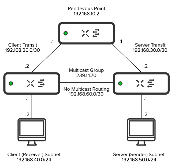
The following topology will be used for our example:
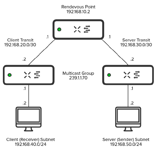
Note: It's recommended to place the Multicast Source into the same subnet as the Rendezvous Point. This is to prevent PIM Registers from being sent and reduce network overhead. However, this topology is being used to show the complete traffic flow associated with PIM-SM.
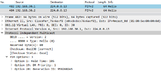
Step 1:
Once Multicast Routing has been enabled on an SVI, PIM Hellos will be sent to the multicast address of 224.0.0.13. This is to discover and form adjacencies with PIM Neighbors.
You can find the current PIM Neighbors by selecting the switch in question under Switch > Monitor > Switches and running Multicast Routing under the Tools tab.

Note: In order for multicast traffic to traverse L3 boundaries, Multicast Routing must be enabled on the entire path between Sender and RP, and Receiver and RP, with adjacencies formed across each segment.
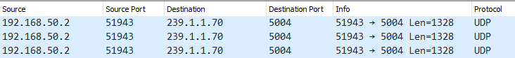
Step 2:
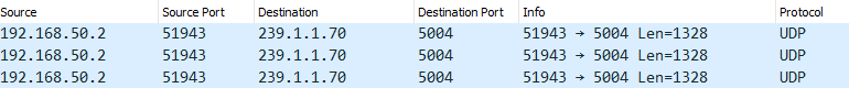
The server initiates the stream to the multicast address of 239.1.1.70:
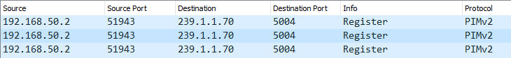
Step 3:
The server switch encapsulates part of the stream into a PIM-Register and forwards it to the RP. While the Destination IP is 239.1.1.70, the Destination MAC will be the MAC of the RP, or the next-hop MAC until it reaches the RP:
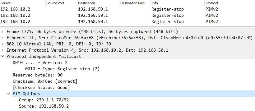
At first, no client was attempting to access the stream so the RP responded back with a PIM Register-Stop. Expanding the PIM Options, the example source (192.168.50.2) and group (239.1.1.70) addresses can be seen:
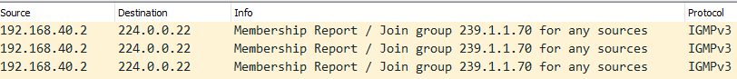
Step 4:
A client attempts to access the stream by sending an IGMP Membership Report for 239.1.1.70.
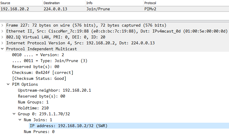
A PIM Join is generated and sent towards the RP. This is evident by the IP of our RP (192.168.10.2) as shown below:
Step 5:
Upon receipt of the PIM Join, the RP will now forward the multicast traffic down towards the client requesting the stream.
Common Issues
RPF (Reverse Path Forwarding) Check
Reverse Path Forwarding is a loop-prevention mechanism that validates the source of a multicast stream. If the source of the stream ingresses on a different interface than expected, the stream will be dropped. This is typically introduced by a missing or misconfigured route to access the source of the stream.
Let's revisit our example topology, but with an additional link added between the Client and Server switch (192.168.60.0/30). A static route has been configured on the Client switch so that the Sender (192.168.50.2) is reachable via this new link.
The Client switch will receive the multicast stream via the Client Transit (192.168.20.0/30) link as this is where the PIM Neighbor Adjacency is formed. Upon receipt, the Client switch will check its unicast route table and see that the 192.168.50.0/24 subnet is reachable via the newly established link (192.168.60.0/30) instead. Because the path that the stream ingresses on is different from the path that the Client switch would use to access the source of the stream, the RPF Check fails, and the stream is dropped.
There are two options available to resolve this:
- Adjust the static route on the Client switch so that the server subnet (192.168.50.0/24) is reachable via the Client Transit link (192.168.20.0/30)
- Enable Multicast Routing on the newly established link (192.168.60.0/30), and make sure that the Client and Server switch point to each other as the next hop to reach each other's subnets
Note: For Option 2, the Multicast Stream would initially flow through the RP via the Shared Tree Path. After the Client switch receives the multicast stream, it'll send a PIM Join towards the Server switch as it recognizes it as a more optimal path to reach the source of the stream. The path will then transition from the Shared Tree to Source Tree, allowing traffic to bypass the RP and flow directly between client and server.
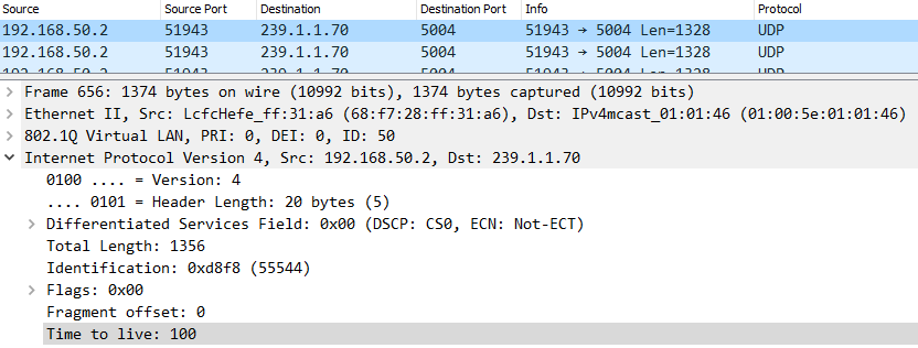
TTL (Time-To-Live)
The TTL is put in place in order to help reduce the impact of routing loops. The TTL value of a packet will decrement with every hop until it reaches a value of "0," in which it's then discarded. The TTL must be set to a value high enough to accommodate for the number of hops between the multicast sender and receiver.
Some applications use a default TTL of "1" that will need to be adjusted, as a value of "1" indicates that the packet isn't routable. If there are issues with the application, it may also cause the stream to be sent with an incorrect value as well.
You can find the TTL by selecting any packet of the multicast stream, and expanding its "IPv4" section. Below, we can see the TTL of the stream was set to "100:"