
Configuring Spanning Tree on Meraki Switches (MS)
Click 日本語 for Japanese
Spanning Tree (STP, RSTP, RPVST+)
Spanning tree (IEEE 802.1D) and Rapid spanning tree (IEEE 802.1w) are both standards-based protocols. The MS series supports these protocols for maximum interoperability with other vendor switches. It is important to take note of the following deployment steps when installing an MS series switch in an existing switch infrastructure.
Network-wide STP settings, including enabling RSTP and setting the bridge priority on MS switches, can be configured in the Meraki Dashboard. Port level STP settings, including enabling or disabling RSTP on a port and configuring STP guards, can also be configured.
Learn more with this free online training course on the Meraki Learning Hub:
Configuring STP Globally
Network-wide STP configurations can be made from the STP configurations section of the Switch settings page on the dashboard. To get to this section:
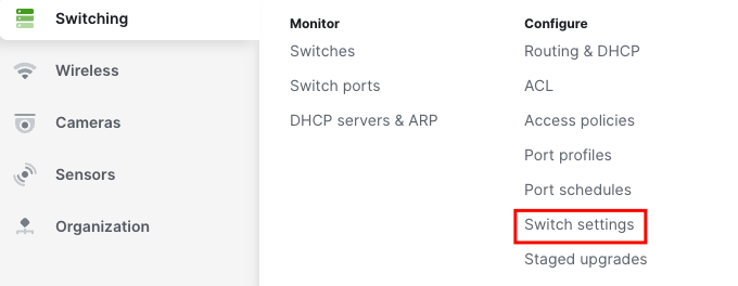
1. Navigate to Switching > Configure > Switch settings.
2. Scroll to the STP configuration section.

Enable RSTP Globally
To enable RSTP globally, select the "Enable RSTP" option. To disable it, simply deselect the box.

| Option | Description |
| Enable RSTP | Enabling RSTP globally allows all of the switches in the network to participate in Spanning Tree processes. RSTP is enabled globally by default; individual ports can be configured to disable RSTP. It is recommended that RSTP remain enabled. |
| Disable RSTP | RSTP may be disabled globally. Disabling RSTP globally removes all the switches in the network from participating any STP processing including any STP guard configuration. Disabling RSTP is not recommended. When RSTP is disabled globally, no ports may be configured to enable RSTP. |
Please note: C9K/MS390 runs single instance (0), single region (region1), and single revision (revision 1) MSTP. This is essentially Rapid Spanning-Tree. Please make sure for interoperability with any other non-Meraki platforms, to either run Rapid Spanning-tree or MSTP (not PVST or any iteration, nor any other vendor specific STP implementation). This will ensure that there are no issues with compatibility and functionality.
Example of an IOS device compatible configuration:
spanning-tree mode mst
spanning-tree mst configuration
 name region1
 revision 1
spanning-tree mst 0 priority 4096
Set Bridge Priority
You can configure the STP bridge priority of any Meraki switch in your network from the STP bridge priority field.
1. Select Set the bridge priority for another switch or stack.

2. Under Switches/Stacks, enter the name of the switch or switch stack on which you want to configure the STP priority.

3. In the dropdown under the Bridge priority, select the STP priority that you would like to assign to the switch.

The default priority for all Meraki switches is 32768. It is recommended that you set the priority of your desired root bridge to 4096 to ensure its election. The root bridge should be a switch in the center of the network, near high traffic sources (such as servers), to optimize traffic flow across the network. Using priority 0 is also acceptable for the root, but leaves no room for modification when replacing a core switch in production or modifying behavior temporarily.
It is best practices to set a layered approach to the STP priorities in a network. For instance, if there is a clear Core <> Distribution <> Access Layer, priorities should be Core (4096), Distribution (16384), and Access (61440). At no point in a production network should you leave the any switch at its default configurations.
Reset a Bridge Priority
To remove an STP priority configuration from a Meraki switch and restore the default priority value, select the bin icon as shown below to the right of the priority configuration.

Save Changes to Global STP Configuration
Select Save changes.

Configuring Rapid-PVST+
C9350s running IOS XE 17.18 will use MST Instance 0 if RPVST+ is configured. Rapid PVST+ support for C9350s will be added in IOS XE 26.1.1.
Configuring RPVST+ is similar to configuring RSTP however there’s an additional column called VLAN list so that the bridge priority can be configured on a per VLAN basis. This feature is currently only available for Catalyst switches running firmware IOS XE 17.18.1+.
First you need to set the Spanning Tree mode to RPVST+.

After setting the mode to RPVST+, the VLAN list column will appear. Here’s an example of setting the bridge priority on the same switch but for different VLANs.

Configure Port Level STP
Port level STP configurations can be made from the switch port configuration menu from the dashboard. To access the switch port configuration menu:
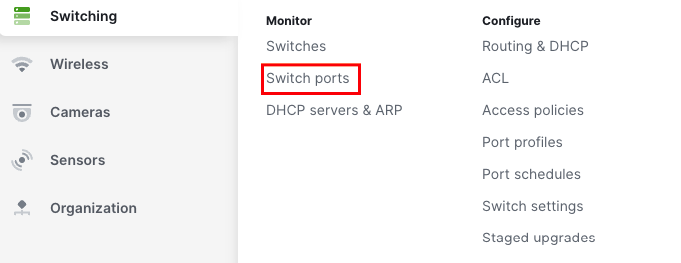
1. Navigate to Switching > Monitor > Switch ports.
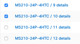
2. Choose the port(s) you wish to configure by selecting the box(es) to the left of the port name(s).
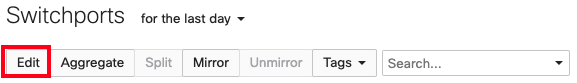
3. Select Edit at the top of the page.
The switch port configuration menu will then be displayed.
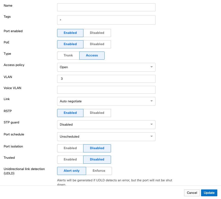
Enabling RSTP on a Switch Port
In the RSTP field of the switch port configuration menu, you may select Enabled or Disabled.

| Option | Description |
| Enabled |
RSTP must be enabled globally (see "Enable RSTP Globally") for any ports to be able to participate in Spanning Tree processes. When RSTP is enabled globally, RSTP will be enabled at the port level by default. A disabled port can be re-enabled by selecting Enabled. While RSTP is enabled on a switch port, that port is able to participate in Spanning Tree processes. It is recommended that RSTP be enabled on all ports. |
| Disabled | RSTP may be disabled at the port level. Disabling RSTP on a port removes the port from any STP processing including any STP guard configuration. Disabling RSTP on a port is not recommended unless the client device connected to the port is incompatible with STP. If RSTP is disabled globally, all ports will have RSTP disabled and cannot have it enabled. |
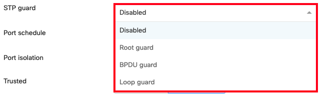
Configuring STP Guard on a Switch Port
From the drop-down in the STP guard configuration option, you may select Disabled, Root guard, BPDU guard, or Loop guard.
| Option | Description |
| Disabled | STP Guard is disabled by default. It applies no STP guard functionality to the port. |
| Root guard | Root guard is used to protect the Spanning Tree topology of a network by enforcing the location of the Root Bridge. If a port with Root Guard enabled on it receives a superior BPDU, the port will transition into an STP-inconsistent state. In this state, the port will still process BPDUs but will not learn MAC addresses or forward traffic. It is recommended that Root Guard be applied to ports connecting to neighboring, downstream switches that should not be the Root Bridge, to prevent a superior BPDU from being received on the port and causing the election of an unexpected Root Bridge. |
| BPDU guard |
BPDUs - Bridge Protocol Data Units - are informational messages communicated between all switches in a Spanning Tree instance to maintain STP consistency. BPDU Guard is used to protect the Spanning Tree topology of a network by enforcing STP domain borders. If a port with BPDU Guard enabled on it receives a BPDU, the port will transition to a disabled state. It is recommended that BPDU Guard be applied to all access ports or client-facing ports that are not intended to be connected to a neighboring switch.
For MS Classic Switches if no BPDU traffic is detected on the target port for 15 seconds, the BPDU Guard function remains enabled and the port automatically recovers(i.e. classic switches will transition back to forwarding with BPDU guard if it stops receiving BPDUs). |
| Loop guard | Loop guard is used to protect a network from unidirectional loops. A unidirectional link failure may stop a port in the blocking state from receiving BPDUs causing it to erroneously transition the forwarding state, creating a loop in the network. If a non-designated port with Loop Guard enabled stops receiving BPDUs, it will transition into a loop-inconsistent blocking state. In this state, the port will still process BPDUs but will not learn MAC addresses or forward traffic, thereby preventing a loop from forming. It is recommended that Loop Guard be enabled on non-designated fiber ports in physically redundant topologies. It is also recommended that Loop Guard be paired with Unidirectional Link Detection (UDLD). For more information on UDLD, check out our Unidirectional Link Detection article. |
Configuring Portfast Trunk on a Switch Port
Portfast Trunk allows a trunk port to more quickly transition to the STP Forwarding state. To enable this feature, toggle the Portfast Trunk setting to Enabled in the Type configuration area.
Note: This feature is supported starting with IOS XE 26.1.1. To utilize portfast trunk please upgrade to IOS XE 26.1.1 or any later releases.
.png?revision=1)
-
Before enabling this feature, make sure that there are no loops in the network between the trunk port and the connected end-device as it may lead to network instability.
-
Enabling this feature allows the IOS XE portfast trunk to be enabled on trunk ports, applying the spanning-tree portfast trunk option to the port(s) in question.
Save Changes to a Switch Port’s STP Configuration
Select Update at the bottom of the switch port configuration menu to save your configuration.

For deployments with mixed Meraki and none Meraki switches please refer to the section below for protocol interoperability.
Interoperability Terms and Guidelines
Root bridge
When connecting access devices including the Meraki MS series switches, it is important to first ensure that a root bridge has been properly configured. In a larger switch fabric, this is typically done on the core switch.
Spanning tree will use several values to elect the root bridge. Once elected, this information is displayed per switch in the Meraki dashboard interface under Switch > Monitor > Switches.
Automatic edge port
MS switches will automatically place all access interfaces into EDGE mode. This will cause the interface to immediately transition the port into STP forwarding mode upon linkup. The port still participates in STP. So if the port is to be a part of the loop, the port eventually transitions into STP blocking mode.
Note: MS390 running <=12.28 firmware does not support edge-port (portfast). To utilize portfast please upgrade to 12.28.1 or any later releases.
Protocol interoperability
Several other protocols have been developed including pre-standard and non-standard protocols to either improve upon or facilitate the same functionality of spanning tree. It may be necessary to connect a Meraki MS series switch to an existing infrastructure running one of these protocols.
MSTP (802.1s)
MSTP is an expansion of RSTP and adds a per-VLAN spanning tree instance to make use of better paths on each VLAN. MSTP is fully compatible with RSTP bridges, in that an MSTP BPDU can be interpreted by an RSTP bridge as an RSTP BPDU. Meraki switches do not support MSTP but are compatible and will see all MSTP instances as a single RSTP region.
Note: The MS390/C9K runs single MSTP instance by default (instance 0) and is not configurable for more than 1 instance. This aligns the platform to maintain compatibility with all other MS switches running Rapid Spanning-tree.
PVST/PVST+
This is a Cisco proprietary protocol on Catalyst/Nexus switches that is compatible with spanning tree (802.1D). It is important to note however that because PVST/PVST+ is a multi-VLAN spanning tree protocol, in order for the MS series switches to participate in spanning tree a spanning tree instance must be running on VLAN 1 of all switches and VLAN 1 is allowed on all trunk ports running PVST+ so that BPDUs are seen by the Meraki switches in the topology. Connecting an MS series to an existing switch fabric running PVST+ will force the MS series switch(es) to run in legacy mode (STP) which can increase convergence time. In this configuration, the MS series switches should never be the STP Root Bridge.
Note: When connecting a PVST+ bridge to an MS series switch, make sure both ports are configured as an 802.1Q trunk. Otherwise, the PVST+ bridge will go into a blocking state due to port inconsistency. To avoid any issues with STP, it is recommended to convert the Cisco Catalyst environment to single instance MSTP. This will ensure maximum compatibility in the STP environment.
Rapid-PVST
This is a Cisco proprietary protocol on Catalyst/Nexus switches that is compatible with spanning tree (802.1D) and RSTP (802.1w). It is important to note however that as Rapid-PVST is a multi-VLAN spanning tree protocol, MS series switches can participate in spanning tree only when a spanning tree instance is running on VLAN 1 of all switches. In addition, VLAN 1 must be allowed on all trunk ports running Rapid-PVST, so that BPDUs are seen by the Meraki switches in the topology. In this configuration, the MS series switches should never be the STP Root Bridge.
Note: To avoid unexpected issues where an MS is between two R-PVST switches (such as a Cisco Catalyst Root Bridge < MS > Catalyst switch). It is recommended to convert the topology to a MSTP on the Catalyst switches. This will avoid potential port inconsistency errors and other issues that may cause instability in the STP topology.