
SD-WAN and Traffic Shaping
Click 日本語 for Japanese
The MX appliance and Z-series gateway include an integrated Layer 7 packet inspection engine, enabling you to set QoS policies, load balancing, and prioritization based on traffic types and applications.
Uplink configuration
This section allows you to configure bandwidth settings, uplink statistics, and list update interval.
Uplink bandwidth settings
This option allows you to configure the upload and download bandwidth of the uplinks. This information is needed for traffic load balancing between the active WAN ports as well as for limiting upload and download traffic. You can configure WAN 1, WAN 2, and the cellular uplink individually. To configure specific upload and download bandwidths for a particular uplink, click the details button next to that uplink's bandwidth slider. The maximum value for each WAN interface is based on the rating of the specific model MX.
Uplink bandwidth settings apply to live tools and WAN connectivity monitoring (with the exception of the "dashboard throughput" tool) and available bandwidth will be split between client traffic flows and these appliance-sourced traffic flows. Extremely low upload bandwidth limits (50kbps or less) may interfere with live tool functionality.
Uplink Statistics
Clicking the Add Your Destination option allows you to add a custom destination for the MX to continually test ICMP connectivity to monitor latency and packet loss. These destinations cannot be private addresses across VPN tunnels and must be reachable through the WAN interface of the MX. Additionally, they must respond to ICMP traffic. It is good practice to include the MX's default gateway to monitor the directly connected link. The results for these tests will be visible at Security & SD-WAN > Monitor > Appliance status > Uplink > Historical data. Hostnames/FQDNs are not supported for uplink statistics monitoring.
MXs and Zs with integrated cellular will not send ICMP Uplink Statistics tests through their cellular interface. This is designed to help reduce the amount of traffic that is sent out of these uplinks. If there is a requirement to send ICMP tests for Uplink Statistics, please reach out to Meraki Support to have this functionality enabled. Please note that only tests to Google DNS (8.8.8.8) will be sent, not to any other Uplink Statistics destinations.
List update interval
This setting determines how often the MX should check for updates to security lists. You can specify an Hourly, Daily, or Weekly update interval. To specify different intervals depending on which uplink is being used to download lists, click details. This can be useful if you want to control bandwidth usage due to security list downloads on a low-bandwidth WAN link or cellular uplink.
Features affected by this setting include IDS/IPS and Malware Scanning.
Uplink selection
Primary uplink
This option determines which uplink should be the primary connection. VPN traffic and management traffic to the Meraki Dashboard use the primary uplink. If load balancing is disabled, all traffic will use the primary uplink unless an uplink preference specifies otherwise. Enhanced Failover logic will also apply in the event of a WAN flap.
Load balancing
When enabled, load balancing spreads Internet traffic across both uplinks proportional to the WAN 1 and WAN 2 bandwidths specified above.
Example: If WAN 1's bandwidth is 9 Mbps and WAN 2's bandwidth is 1 Mbps, the load-balancing algorithm sends 90% of the traffic through the WAN 1 uplink and 10% of the traffic through the WAN 2 uplink.
Multi-Uplink AutoVPN
This option is used to determine if AutoVPN tunnels should be formed over only the primary uplink or over all active uplinks simultaneously. There are two options that can be configured:
- Enabled: Create VPN tunnels over all of the available uplinks.
- Disabled: Do not create VPN tunnels over non-primary uplinks, unless the primary uplink fails.
Flow preferences
Use this option to direct traffic matching a Layer 3 definition via a particular uplink. Some common use cases involve sending traffic from different VLANs through different Internet uplinks, or sending a particular type of traffic such as FTP traffic out a particular uplink based on the destination port.
Note: ICMP traffic is not subject to traffic shaping rules. As a result, flow preferences will have no impact on ICMP traffic.
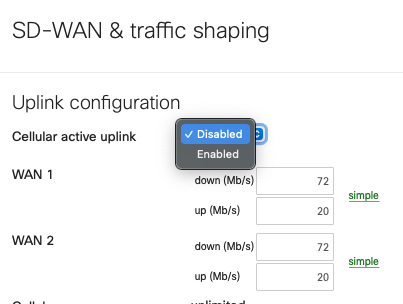
SD-WAN over Cellular Active Uplink
To use SD-WAN over cellular, the MX needs to be running MX16.2+ and have the feature enabled on an integrated cellular MX (MX67C and MX68CW only).
With this feature enabled, the cellular connection that was previously backup-only, can be configured as an active uplink in the SD-WAN & traffic shaping page as shown below:
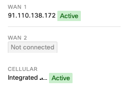
When this toggle is set to Enabled, the cellular interface details, found on the Uplink tab of the Appliance status page, will show as Active even when a wired connection is also active, as shown below:
Given that this feature takes ownership of the WAN2 logic, enabling it means that the use of two wired networks is not supported. This is because only two WAN connections can be used concurrently.
This means that the wired connection can only be connected to Internet port 1 or WAN 1.
When using this feature on an MX67C, this results in the port LAN2 being unusable because LAN2 is a multi-use port that can also operate as WAN2.
When using this feature on an MX68CW, this results in the Internet 2 port being unusable.
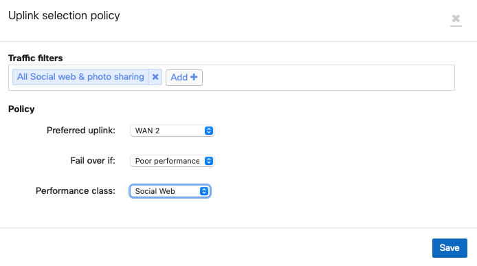
As such, to configure an SD-WAN policy to utilize the cellular connection, associate it with WAN2 as shown below:
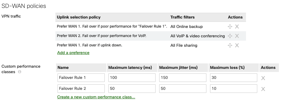
SD-WAN policies
SD-WAN policies can be configured to control and modify the flows for specific VPN traffic. With multiple WAN uplinks, the WAN appliance will proactively build multiple tunnels with each available WAN interface. In the case where there are redundant WAN connections on the WAN appliance, traffic flows based on the type of traffic traversing the VPN connections can also be configured to allow for best performance. Custom policies set to desired preferences can be set to ensure traffic flows take the appropriate path based on your environment. If a WAN connection that normally handles traffic such as file transfers begins to have performance issues, the Cisco Meraki WAN appliance can dynamically change the VPN connection to an alternative WAN uplink. This is done with custom policies or predetermined policies on the dashboard. It is encouraged to configure said policies in your deployment to best fit the needs based on the nature of the traffic and the capabilities of the WAN connections available on the WAN appliance.
This option appears after Multi-Uplink Auto VPN is enabled.
Once configured, these custom VPN policies are enforced on all VPN traffic that matches the specifications you select. Example configurations can be found in the Meraki SD-WAN configuration guide.
If you do have questions about what policies are best for your deployment, you can always reach out to either a Meraki Sales Engineer or your Meraki partner for a consultation on what best fits your needs.
On MX18.2 firmware while using MultiWAN MXs SD-WAN policies and load balancing policies do not apply to WAN3. You can reference MultiWAN_Backup_Uplink
Global bandwidth limits
This setting allows you to set limits on each client device's total network traffic (incoming / outgoing). The minimum throughput limit is 20 Kb/s. Click details or simple to switch between two possible modes.
- simple: Single setting that applies to both upload and download traffic throughput. Move the slider control right or left to set the limits.
- details: Allows you to set different limits on upload and download throughput. Enter the limits manually in Kb/s. You can also use this mode to create more precise per-client limits than in simple mode.
Enable SpeedBurst: To provide a better user experience in bandwidth-limited environments, an administrator can enable SpeedBurst by selecting the Enable SpeedBurst checkbox. SpeedBurst allows users to exceed their assigned limit in a burst for a short period of time. This provides a more satisfying Internet browsing experience. It also prevents any one user from using more than their fair share of bandwidth over the longer term. Users are allowed up to four times their allotted bandwidth limit for a period of up to five seconds.
Traffic shaping rules
To optimize your network, you can create shaping policies to apply per-user controls on a per-application basis. This allows you to reduce bandwidth for recreational applications such as peer-to-peer file sharing programs, and to prioritize bandwidth for your business-critical enterprise applications. The Meraki dashboard has a set of default rules that can be enabled/disabled.
You can also create custom rules and apply them to your desired traffic signatures. If a custom-defined rule is created that overlaps with a default rule, then the custom-defined rule will take effect.
Traffic shaping rules will also apply to traffic sent over an AutoVPN tunnel between Meraki devices, but do not apply to traffic that passes over a non-Meraki VPN tunnel.
The use of NBAR will add categories to the traffic shaping section that were not available before. More information about NBAR can be found at Next-gen Traffic Analytics - Network-Based Application Recognition (NBAR) Integration.
Creating Shaping Rules
Click Create a new rule to add a traffic shaping rule. Traffic shaping policies consist of a series of rules that are performed in the order in which they appear in the policy, similar to custom firewall rules. There are two main components to each rule: the type of traffic to be limited or shaped (rule definition), and how that traffic should be limited or shaped (rule actions).
Note: Traffic shaping rules are applied per client flow. For example, setting a limit of 5 Mbps for three different traffic shaping rules will allow 5 Mbps to each client flow matching those respective rules.
Rule Definition
Rules can be defined in two ways:
- You can select from various predefined application categories such as Video & Music, Peer-to-Peer, or Email.
- You can create rules by specifying HTTP hostnames (for example, salesforce.com), port numbers (such as 80), IP ranges (such as 192.168.0.0/16), or IP address range and port combinations (such as 192.168.0.0/16:80).
The rule action is enforced on all traffic that matches the specifications you select. By clicking Add expression, you can create additional specifications for traffic that is shaped according to the same rule action.
Note: The rule for HTTP hostname does not require a catch-all "*" (asterisk) to be prefixed to include subdomains. For example, the hostname 'google.com' will include its subdomains as well.
Rule Actions
Traffic matching specified rule sets can be shaped or prioritized.
-
Bandwidth limits can be specified to ignore any limits specified for the whole network, to obey the specified limits, or to apply more-restrictive limits than the network limits. Use the bandwidth slider control to choose the appropriate limit for each type of traffic. To specify asymmetric limits on uploads and downloads, click details next to the bandwidth slider control.
-
Priority can be set to High, Normal, or Low, allowing the MX series to prioritize a given network flow relative to the rest of the network traffic. Note that Realtime is reserved for traffic tagged with a DSCP bit value mapping to EF46 only.
-
Firmware 18.2 and above: Class Based Weighted Fair Queueing with Deficit Round Robin is enforced on token bucket allocations. Allocation ratios are as follows:
-
Realtime: 8
-
High: 4
-
Normal: 2
-
Low: 1
-
-
With deficit round robin, queues that do not actively have traffic to send will see their tokens allocated to the next queue in line. This prevents starvation for lower priority queues while continuing to prioritize VoIP traffic and other manually defined high-priority traffic.
-
-
Firmware 18.1 and lower: Strict Priority Queueing is enforced with the following ratios on token bucket allocations
-
High: 4/7
-
Normal: 2/7
-
Low: 1/7
-
-
-
Quality of Service (QoS) prioritization can be applied to Layer 3 traffic. To prioritize traffic at Layer 3, select a value for the DSCP tag in the IP header for all incoming and outgoing IP packets. This also affects the Wi-Fi Multimedia (WMM) priority of the traffic.
For the Priority feature to work as desired, ensure that uplink throughput settings are accurate.
For QoS prioritization to work as desired, ensure that upstream networking equipment also supports QoS prioritization.
Creating a Sample Traffic-Shaping Rule
Here is an example of how to set up a traffic shaping policy with multiple traffic-shaping rules. For additional examples, refer to our Simple Traffic Shaping Strategy article.
To prioritize VoIP and minimize peer-to-peer traffic and gaming, create a new traffic-shaping policy by following the steps below:
- In the Rule #1 Definition pull-down menu, choose VoIP & video conferencing.
- Under Bandwidth limit, choose Ignore network limit.
- In the Priority pull-down menu, choose High.
- Under DSCP tagging, choose 7 (WMM Voice).
- Click Add a new shaping rule.
- In the Rule #2 Definition pull-down menu, choose Peer-to-peer (P2P).
- Click Add an expression.
- In the new pull-down menu, choose Gaming.
- In the Bandwidth limit section, click Choose a limit and use the slider to choose a low throughput (the minimum is 20 Kb/s).
- Save your changes by clicking Save Changes at the bottom of the page.
Web cache
This option is not available on the MX64, MX64W, MX65, MX65W, MX67, MX67W, MX67C, MX68, MX68W, MX68CW, MX75, MX85, MX95, MX105, Z3, Z3C, Z4, Z4C devices.
When HTTP content caching is enabled, the MX will cache web content on its solid-state drive (SSD). This can improve end-user experience by reducing page load times and file download times for frequently accessed web content. Web caching only works for static HTTP content, so it will not be able to cache sites such as YouTube.
This feature is recommended only for sites with limited bandwidth. Locations with over 20 Mbps bandwidth will likely not benefit from content caching.