
Meraki SD-WAN
Overview
All Cisco Meraki WAN Appliances are equipped with SD-WAN capabilities that enable administrators to maximize network resiliency and bandwidth efficiency. This guide introduces the various components of Meraki SD-WAN and the possible ways in which to deploy a Meraki AutoVPN architecture to leverage SD-WAN functionality, with a focus on the recommended deployment architecture.
What is SD-WAN?
Software-defined WAN (SD-WAN) is a suite of features designed to allow the network to dynamically adjust to changing WAN conditions without the need for manual intervention by the network administrator. By providing granular control over how certain traffic types respond to changes in WAN availability and performance, SD-WAN can ensure optimal performance for critical applications and help to avoid disruptions of highly performance-sensitive traffic, such as VoIP. Additionally, SD-WAN can be a scalable and often much cheaper alternative to traditional WAN circuits like MPLS lines.
Key Concepts
Before deploying SD-WAN, it is important to understand several key concepts.
Concentrator Mode
All WAN Appliances can be configured in either NAT or VPN concentrator mode. There are important considerations for both modes. For more detailed information on concentrator modes, click here.
One-Armed Concentrator
In this mode, the WAN Appliance is configured with a single Ethernet connection to the upstream network. All traffic will be sent and received on this interface. This is the recommended configuration for WAN Appliances serving as VPN termination points into the datacenter.
NAT Mode Concentrator
It is also possible to take advantage of the SD-WAN feature set with an WAN Appliance configured in NAT mode acting as the VPN termination point in the datacenter.
VPN Topology
There are several topology options available for VPN deployment.
Split Tunnel
In this configuration, branches will only send traffic across the VPN if it is destined for a specific subnet that is being advertised by another WAN Appliance in the same Dashboard organization. The remaining traffic will be checked against other available routes, such as static LAN routes and third-party VPN routes, and if not matched will be NATed to the WAN Appliance WAN IP address and sent out of WAN interface of the branch WAN Appliance, unencrypted.
Full Tunnel
In full tunnel mode all traffic that the branch or remote office does not have another route to is sent to a VPN hub.
Hub and Spoke
In a hub and spoke configuration, the WAN Appliances at the branches and remote offices connect directly to specific WAN Appliances and will not form tunnels to other WAN Appliance or Teleworker devices in the organization. Communication between branch sites or remote offices is available through the configured VPN hubs. This is the recommended VPN topology for most SD-WAN deployments.
VPN Mesh
It is also possible to use a VPN "mesh" configuration in an SD-WAN deployment.
In a mesh configuration, a WAN Appliance at the branch or remote office is configured to connect directly to any other WAN Appliances in the organization that are also in mesh mode, as well as any spoke WAN Appliances that are configured to use it as a hub.
Datacenter Redundancy (DC-DC Failover)
Deploying one or more WAN Appliances to act as VPN concentrators in additional datacenters provides greater redundancy for critical network services. In a dual- or multi-datacenter configuration, identical subnets can be advertised from each datacenter with a VPN concentrator mode WAN Appliance.
In a DC-DC failover design, a spoke site will form VPN tunnels to all VPN hubs that are configured for that site. For subnets that are unique to a particular hub, traffic will be routed directly to that hub so long as tunnels between the spoke and hub are established successfully. For subnets that are advertised from multiple hubs, spokes sites will send traffic to the highest priority hub that is reachable.
Warm Spare (High Availability) for VPN concentrators
When configured for high availability (HA), one WAN Appliance serves as the primary unit and the other WAN Appliance operates as a spare. All traffic flows through the primary WAN Appliance, while the spare operates as an added layer of redundancy in the event of failure.
Failover between WAN Appliances in an HA configuration leverages VRRP heartbeat packets. These heartbeat packets are sent from the Primary WAN Appliance to the Spare WAN Appliance out the singular uplink in order to indicate that the Primary is online and functioning properly. As long as the Spare is receiving these heartbeat packets, it functions in the passive state. If the Passive stops receiving these heartbeat packets, it will assume that the Primary is offline and will transition into the active state. In order to receive these heartbeats, both VPN concentrator WAN Appliances should have uplinks on the same subnet within the datacenter.
Only one MX license is required for the HA pair, as only a single device is in full operation at any given time.
Connection Monitor
Connection monitor is an uplink monitoring engine built into every WAN Appliance. The mechanics of the engine are described in this article.
SD-WAN Technologies
The Meraki SD-WAN implementation is comprised of several key features, built atop our AutoVPN technology.
Dual-Active VPN Uplinks
Prior to the SD-WAN release, Auto VPN tunnels would only form only over a single interface. With the SD-WAN release, it is now possible to form concurrent AutoVPN tunnels over both Internet interfaces of the WAN Appliance.
The ability to form and send traffic over VPN tunnels on both interfaces significantly increases the flexibility of traffic path and routing decisions in AutoVPN deployments. In addition to providing administrators with the ability to load balance VPN traffic across multiple links, it also allows them to leverage the additional path to the datacenter in a variety of ways using the built-in Policy-based Routing and dynamic path selection capabilities of the WAN Appliance.
Policy-Based Routing (PbR)
Policy-based Routing allows an administrator to configure preferred VPN paths for different traffic flows based on their source and destination IPs and ports.
Dynamic Path Selection
Dynamic path selection allows a network administrator to configure performance criteria for different types of traffic. Path decisions are then made on a per-flow basis based on which of the available VPN tunnels meet these criteria, determined by using packet loss, latency, and jitter metrics that are automatically gathered by the WAN Appliance.
Performance Probes
Performance-based decisions rely on an accurate and consistent stream of information about current WAN conditions in order to ensure that the optimal path is used for each traffic flow. This information is collected via the use of performance probes.
The performance probe is a small payload (approximately 100 bytes) of UDP data sent by spokes to hubs or by hubs to other hubs over all established AutoVPN tunnels every 1 second. WAN Appliances track the rate of successful responses and the time that elapses before receiving a response. This data allows the WAN Appliance to determine the packet loss, latency, and jitter over each AutoVPN tunnel in order to make the necessary performance-based decisions.
High-Level Architecture
This guide focuses on the most common deployment scenario but is not intended to preclude the use of alternative topologies. The recommended SD-WAN architecture for most deployments is as follows:
- WAN Appliance at the datacenter deployed as a one-armed concentrator.
- Warm spare/High Availability at the datacenter.
- OSPF route advertisement for scalable upstream connectivity to connected VPN subnets.
- Datacenter redundancy
- Split tunnel VPN from the branches and remote offices
- Dual WAN uplinks at all branches and remote offices
SD-WAN Objectives
This guide focuses on two key SD-WAN objectives:
-
Redundancy for critical network services
-
Dynamic selection of the optimal path for VoIP traffic
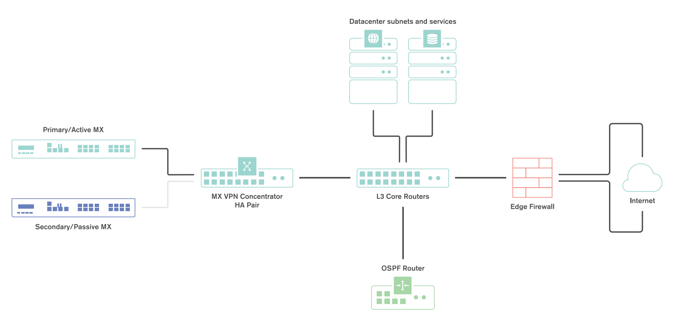
Example Topology
The following topology demonstrates a fully featured SD-WAN deployment, including DC-DC failover for the redundancy.
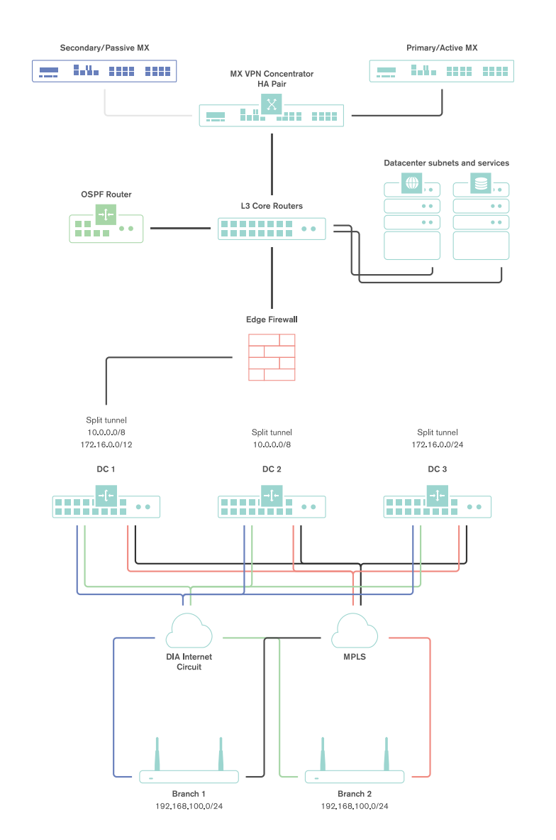
Both tunnels from a branch or remote office location terminate at the single interface used on the one-armed concentrator.
High Level Traffic Flow
The decisions for path selection for VPN traffic are made based on a few key decision points:
- Whether VPN tunnels can be established on both interfaces
- Whether dynamic path selection rules are configured
- Whether Policy-based Routing rules are configured
- Whether load balancing is enabled
If tunnels are established on both interfaces, dynamic path selection is used to determine which paths meet the minimum performance criteria for particular traffic flow. Those paths are then evaluated against the policy-based routing and load balancing configurations.
For a more detailed description of traffic flow with an SD-WAN configuration, please see the appendix.
Failover Times
There are several important failover timeframes to be aware of:
| Service | Failover Time | Failback Time | SD-WAN |
| SD-WAN (Dynamic path selection) | Sub-second* | Sub-second* | Yes |
| AutoVPN Tunnels | 30-40 seconds | 30-40 seconds | No |
| DC-DC Failover | 20-30 seconds | 20-30 seconds | No |
| Warm Spare | 30 seconds or less | 30 seconds or less | No |
| WAN connectivity | 300 seconds or less** | 15-30 seconds | No |
* - Failover times listed here depend on the policy type and configuration. With an Active-Active AutoVPN and performance-based failover rules configured, failover will occur in ~500ms for a packet loss threshold <5% (a custom performance class policy).
In the instances of complete circuit failure (uplink physically disconnected) the time to failover to a secondary path is near instantaneous; less than 100ms.
** - Note that 300 seconds is an absolutely worst case failover for a WAN Appliance in OAC/VPNC mode experiencing an intermittent upstream WAN service degradation (connection monitor based failure). Note that 300 seconds WAN connectivity failover is NOT an SD-WAN failover.
Tunnel Recovery
In certain instances, the upstream NAT device may fail to maintain AutoVPN flows for extended periods of time. In the event that this happens, the WAN Appliance is set to Automatic NAT traversal and the WAN Appliance is unable to reach all configured peers for ten minutes, the WAN Appliance will automatically select new ports and try to initialize a new connection to reestablish the AutoVPN tunnels. The WAN Appliance will record these events in the event log under the topic “VPN tunnel connectivity change”.
Datacenter Deployment
This section will outline the configuration and implementation of the SD-WAN architecture in the datacenter.
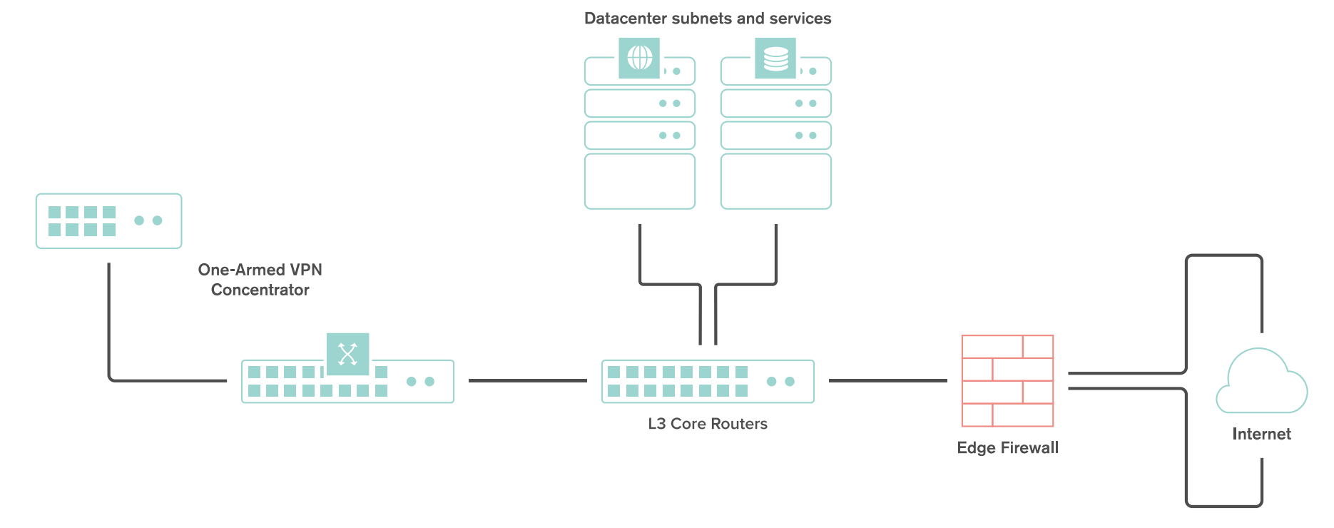
Deploying a One-Armed Concentrator
Example Topology
A one-armed concentrator is the recommended datacenter design choice for an SD-WAN deployment. The following diagram shows an example of a datacenter topology with a one-armed concentrator:
Dashboard Configuration
The Cisco Meraki Dashboard configuration can be done either before or after bringing the unit online.
-
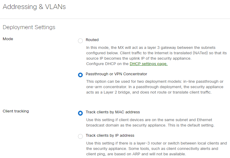
Begin by configuring the WAN Appliance to operate in VPN Concentrator mode. This setting is found on the Security & SD-WAN > Configure > Addressing & VLANs page. The WAN Appliance will be set to operate in Routed mode by default.
-
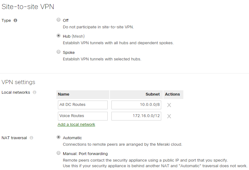
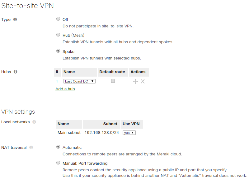
Next, configure the Site-to-Site VPN parameters. This setting is found on the Security & SD-WAN > Configure > Site-to-site VPN page.
- Begin by setting the type to "Hub (Mesh)."
- Configure the local networks that are accessible upstream of this VPN concentrator.
-
For the Name, specify a descriptive title for the subnet.
-
For the Subnet, specify the subnet to be advertised to other AutoVPN peers using CIDR notation
-
-
NAT traversal can be set to either automatic or manual. See below for more details on these two options.
-
An example screenshot is included below:
NAT Traversal
Whether to use Manual or Automatic NAT traversal is an important consideration for the VPN concentrator.
Use manual NAT traversal when:
- There is an unfriendly NAT upstream
- Stringent firewall rules are in place to control what traffic is allowed to ingress or egress the datacenter
- It is important to know which port remote sites will use to communicate with the VPN concentrator
If manual NAT traversal is selected, it is highly recommended that the VPN concentrator be assigned a static IP address. Manual NAT traversal is intended for configurations when all traffic for a specified port can be forward to the VPN concentrator.
Use automatic NAT traversal when:
- None of the conditions listed above that would require manual NAT traversal exist
If automatic NAT traversal is selected, the WAN Appliance will automatically select a high numbered UDP port to source AutoVPN traffic from. The VPN concentrator will reach out to the remote sites using this port, creating a stateful flow mapping in the upstream firewall that will also allow traffic initiated from the remote side through to the VPN concentrator without the need for a separate inbound firewall rule.
Adding Warm Spare
This section outlines the steps required to configure and implement warm spare (HA) for a WAN Appliance operating in VPN concentrator mode.
Warm Spare Topology
The following is an example of a topology that leverages an HA configuration for VPN concentrators:
Behaviour
When configured for high availability (HA), one WAN Appliance is active, serving as the primary, and the other WAN Appliance operates in a passive, standby capacity (spare mode). The VRRP protocol is leveraged to achieve failover. Please see here for more information.
Dashboard Configuration
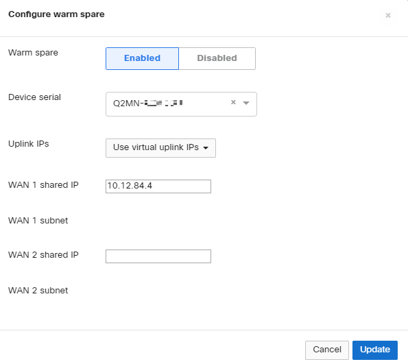
High availability on WAN Appliances requires a second WAN Appliance of the same model. The HA implementation is active/passive and will require the second MX also be connected and online for proper functionality. For more detailed information about MX warm spare, please see here.
High availability (also known as a warm spare) can be configured from Security & SD-WAN > Monitor > Appliance status. Begin by clicking "Configure warm spare" and then "Enabled". Next, enter the serial number of the warm spare WAN Appliance or select one from the drop-down menu. Finally, select whether to use WAN Appliance uplink IPs or virtual uplink IPs.
Uplink IPs
Use Uplink IPs is selected by default for new network setups. In order to properly communicate in HA, VPN concentrator WAN Appliances must be set to use the virtual IP (VIP).
Virtual IP (VIP)
The virtual uplink IPs option uses an additional IP address that is shared by the HA WAN Appliances. In this configuration, the WAN Appliances will send their cloud controller communications via their uplink IPs, but other traffic will be sent and received by the shared virtual IP address.
Configuring OSPF Route Advertisement
WAN Appliances support advertising routes to connected VPN subnets via OSPF.
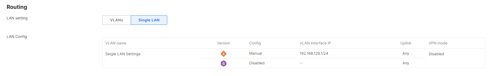
Note: WAN Appliances in Routed mode only support OSPF on firmware versions 13.4+, when using the "Single LAN" LAN setting. OSPF is otherwise supported when the WAN Appliance is in Passthrough or VPN Concentrator mode on any available firmware version. This can be set under Security & SD-WAN > Configure > Addressing & VLANs.
Behaviour
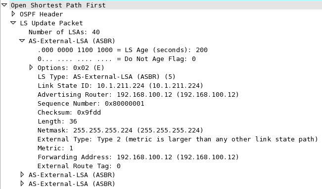
A WAN Appliance with OSPF route advertisement enabled will only advertise routes via OSPF; it will not learn OSPF routes.
When spoke sites are connected to a hub WAN Appliance with OSPF enabled, the routes to spokes sites are advertised using an LS Update message. These routes are advertised as type 2 external routes.
Dashboard Configuration
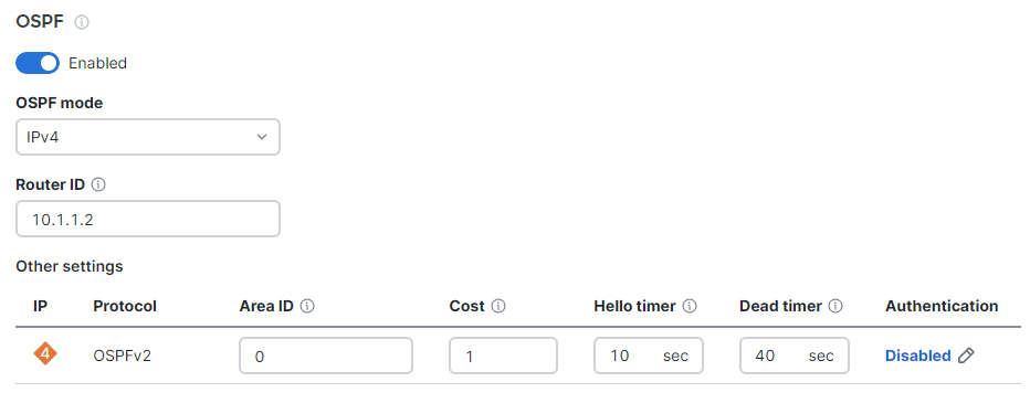
In order to configure OSPF route advertisement, navigate to the Security & SD-WAN > Configure > Site-to-Site VPN page. From this page:
- Set OSPF to Enabled
- Configure the Router ID
- Configure the Area ID
- Adjust the Cost, if desired
- Adjust the Hello timer, if needed
- Adjust the Dead timer, if needed
- Enable and configure MD5 authentication, if needed
Other Datacenter Configuration
WAN Appliance IP Assignment
In the datacenter, a WAN Appliance can operate using a static IP address or an address from DHCP. WAN Appliances will attempt to pull DHCP addresses by default. It is highly recommended to assign static IP addresses to VPN concentrators.
Static IP assignment can be configured via the device local status page.
The local status page can also be used to configure VLAN tagging on the uplink of the WAN Appliance. It is important to take note of the following scenarios:
- If the upstream port is configured as an access port, VLAN tagging should not be enabled.
- If the port upstream is configured as a trunk port and the WAN Appliance should communicate on the native or default VLAN, VLAN tagging should be left as disabled.
- If the port upstream is configured as a trunk and the WAN Appliance should communicate on a VLAN other than the native or default VLAN, VLAN tagging should be configured for the appropriate VLAN ID.
Upstream Considerations
This section discusses configuration considerations for other components of the datacenter network.
Routing
The WAN Appliance acting as a VPN concentrator in the datacenter will be terminating remote subnets into the datacenter. In order for bi-directional communication to take place, the upstream network must have routes for the remote subnets that point back to the WAN Appliance acting as the VPN concentrator.
If OSPF route advertisement is not being used, static routes directing traffic destined for remote VPN subnets to the WAN Appliance VPN concentrator must be configured in the upstream routing infrastructure.
If OSPF route advertisement is enabled, upstream routers will learn routes to connected VPN subnets dynamically.
Firewall Considerations
The WAN Appliance makes use of several types of outbound communication. Configuration of the upstream firewall may be required to allow this communication.
Dashboard & Cloud
The WAN Appliance is a cloud managed networking device. As such, it is important to ensure that the necessary firewall policies are in place to allow for monitoring and configuration via the Cisco Meraki Dashboard. The relevant destination ports and IP addresses can be found under the Help > Firewall Info page in the Dashboard.
VPN Registry
Cisco Meraki's AutoVPN technology leverages a cloud-based registry service to orchestrate VPN connectivity. In order for successful AutoVPN connections to establish, the upstream firewall mush to allow the VPN concentrator to communicate with the VPN registry service. The relevant destination ports and IP addresses can be found under the Help > Firewall Info page in the Dashboard.
Uplink Health Monitoring
The WAN Appliance also performs periodic uplink health checks by reaching out to well-known Internet destinations using common protocols. The full behavior is outlined here. In order to allow for proper uplink monitoring, the following communications must also be allowed:
- ICMP to 8.8.8.8 (Google's public DNS service)
- HTTP port 80
- DNS to the WAN Appliance's configured DNS server(s)
Datacenter Redundancy (DC-DC Failover)
Cisco Meraki WAN Appliances support datacenter to datacenter redundancy via our DC-DC failover implementation. The same steps used above can also be used to deploy one-armed concentrators at one or more additional datacenters. For further information about VPN failover behavior and route prioritization, please review this article.
Branch Deployment
This section will outline the configuration and implementation of the SD-WAN architecture in the branch.
Configuring AutoVPN at the Branch
Prerequisites
Before configuring and building AutoVPN tunnels, there are several configuration steps that should be reviewed.
Subnet Configuration
AutoVPN allows for the addition and removal of subnets from the AutoVPN topology with a few clicks. The appropriate subnets should be configured before proceeding with the site-to-site VPN configuration.
Begin by configuring the subnets to be used at the branch from the Security & SD-WAN > Configure > Addressing & VLANs page.
By default, a single subnet is generated for the WAN Appliance network, with VLANs disabled. In this configuration, a single subnet and any necessary static routes can be configured without the need to manage VLAN configurations.
If multiple subnets are required or VLANs are desired, the VLANs box should be toggled. This allows for the creation of multiple VLANs, as well as allowing for VLAN settings to be configured on a per-port basis.
Configuring AutoVPN
Once the subnets have been configured, Cisco Meraki's AutoVPN can be configured via the Security & SD-WAN > Configure > Site-to-site VPN page in Dashboard.
Configuring Hub and Spoke VPN
From the Security & SD-WAN > Configure > Site-to-Site VPN page:
- Select Spoke for the type
- Under Hubs, select Add a hub
- To connect to additional hubs, select Add a hub and select the VPN concentrator configured in the datacenter deployment steps.
- Additional hubs can be added using the Add a hub link
Hub Priorities
Hub priority is based on the position of individual hubs in the list from top to bottom. The first hub has the highest priority, the second hub the second highest priority, and so on. Traffic destined for subnets advertised from multiple hubs will be sent to the highest priority hub that a) is advertising the subnet and b) currently has a working VPN connection with the spoke. Traffic to subnets advertised by only one hub is sent directly to that hub.
Configuring Allowed Networks
To allow a particular subnet to communicate across the VPN, locate the local networks section in the Site-to-site VPN page. The list of subnets is populated from the configured local subnets and static routes in the Addressing & VLANs page, as well as the Client VPN subnet if one is configured.
To allow a subnet to use the VPN, set the Use VPN drop-down to yes for that subnet.
NAT Traversal
Please refer to the datacenter deployment steps here for more information on NAT Traversal options.
Adding Performance and Policy Rules
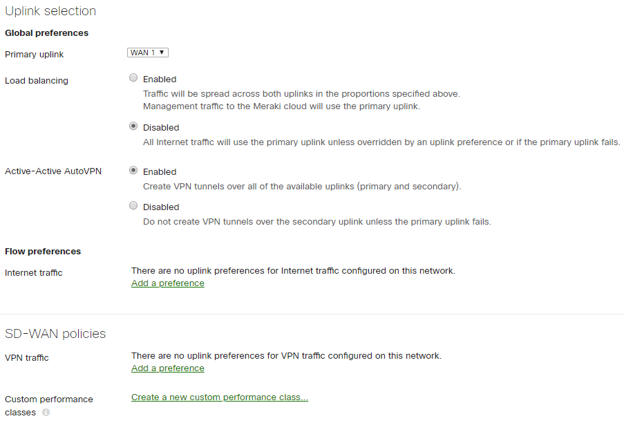
Rules for routing of VPN traffic can be configured on the Security & SD-WAN > Configure > SD-WAN & traffic shaping page in the dashboard.
Settings to configure Policy-based Routing (PbR) and dynamic path selection are found under the SD-WAN policies heading.
The following sections contain guidance on configuring several example rules.
Best for VoIP
One of the most common uses of traffic optimization is for VoIP traffic, which is very sensitive to loss, latency, and jitter. The Cisco Meraki WAN Appliance has a default performance rule in place for VoIP traffic, Best for VoIP.
To configure this rule, click Add a preference under the VPN traffic section.
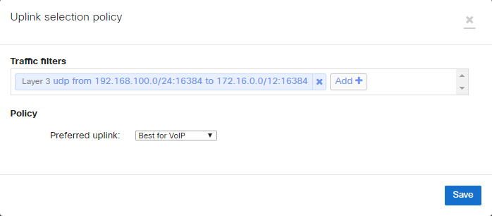
In the Uplink selection policy dialogue, select Custom expressions, then UDP as the protocol and enter the appropriate source and destination IP address and ports for the traffic filter. Select the Best for VoIP policy for the preferred uplink, then save the changes.
This rule will evaluate the loss, latency, and jitter of established VPN tunnels and send flows matching the configured traffic filter over the optimal VPN path for VoIP traffic, based on the current network conditions.
Load Balance Video
Video traffic is increasingly prevalent as technologies like Cisco video conferencing continue to be adopted and integrated into everyday business operations. This branch site will leverage another pre-built performance rule for video streaming and will load balance traffic across both Internet uplinks to take full advantage of available bandwidth.
To configure this, click Add a preference under the VPN traffic section.
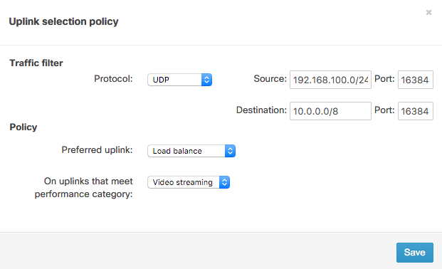
In the Uplink selection policy dialogue, select UDP as the protocol and enter the appropriate source and destination IP address and ports for the traffic filter. For the policy, select Load balance for the Preferred uplink. Next, set the policy to only apply on uplinks that meet the Video streaming performance category. Finally, save the changes.
This policy monitors loss, latency, and jitter over VPN tunnels and will load balance flows matching the traffic filter across VPN tunnels that match the video streaming performance criteria.
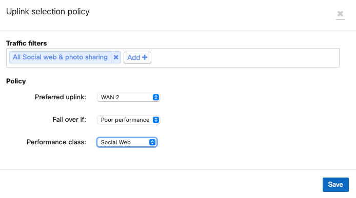
PbR with Performance Failover for Web traffic
Web traffic is another common type of traffic that a network administrator may wish to optimize or control. This branch will leverage a PbR rule to send web traffic over VPN tunnels formed on the WAN 1 interface, but only if that matches a custom-configured performance class.
To configure this, select Create a new custom performance class under the Custom performance classes section.

In the Name field, enter a descriptive title for this custom class. Specify the maximum latency, jitter, and packet loss allowed for this traffic filter. This branch will use a "Web" custom rule based on a maximum loss threshold. Then, save the changes.
Next, click Add a preference" under the VPN traffic section.
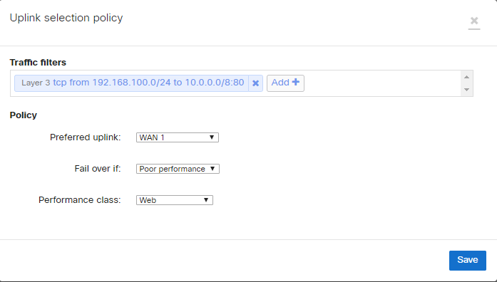
In the Uplink selection policy dialogue, select TCP as the protocol and enter in the appropriate source and destination IP address and ports for the traffic filter. For the policy, select WAN1 for the Preferred uplink. Next, configure the rule such that web traffic will Failover if there is Poor performance. For the Performance class, select "Web". Then, save the changes.
This rule will evaluate the packet loss of established VPN tunnels and send flows matching the traffic filter out of the preferred uplink. If the loss, latency, or jitter thresholds in the "Web" performance rule are exceeded, traffic can fail over to tunnels on WAN2 (assuming they meet the configured performance criteria).
Layer 7 Classification
Best for VoIP
To configure this rule, click Add a preference under the VPN traffic section.
In the uplink selection policy dialogue, click Add+ to configure a new traffic filter. From the filter selection menu, click the VoIP & video conferencing category and then select the desired layer 7 rules. This example will use the SIP (Voice) rule.
Then, select the Best for VoIP performance class for the preferred uplink and save the changes. This rule will evaluate the loss, latency, and jitter of established VPN tunnels and send flows matching the configured traffic filter over the optimal VPN path for VoIP traffic, based on the current network conditions.
WAN Interface Configuration
While automatic uplink configuration via DHCP is sufficient in many cases, some deployments may require manual uplink configuration of the WAN Appliance at the branch. The procedure for assigning static IP addresses to WAN interfaces can be found here.
Some WAN Appliance models have only one dedicated Internet port and require a LAN port be configured to act as a secondary Internet port via the device local status page if two uplink connections are required. This configuration change can be performed on the device local status page on the Configure tab.
SD-WAN over Cellular Active Uplink
To use SD-WAN over cellular the WAN Appliance needs to be running MX16.2+ and have the feature enabled on an integrated cellular MX (MX67C and MX68CW only).
With this feature in place the cellular connection that was previously only enabled as backup can be configured as an active uplink in the SD-WAN & traffic shaping page as per:
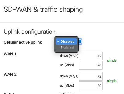
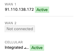
When this toggle is set to 'Enabled' the cellular interface details, found on the 'Uplink' tab of the 'Appliance status' page, will show as 'Active' even when a wired connection is also active, as per the below:
At this point, the cellular connection inherits all the SD-WAN policies associated with WAN2 in the UI. Given this feature takes ownership of the WAN2 logic, this means that when this feature is enabled, the use of 2 wired networks is not supported, as currently only 2 WAN connections can be used concurrently.
This means that the wired connection can only be connected to Internet port 1 or WAN 1.
When using this feature on an MX67C, this results in the port LAN2 being unusable due to the fact that LAN2 is a multi-use port that can also operate as WAN2.
When using this feature on an MX68CW, this results in the Internet 2 port being unusable.
As such, to configured an SD-WAN policy to utilize the cellular connection associate it with WAN2 as per:
FAQ
Does the WAN Appliance support unencrypted AutoVPN tunnels?
No, currently AutoVPN always uses AES-128 encryption for VPN tunnels.
If traffic is encrypted, what about QoS or DSCP tags?
Both QoS and DSCP tags are maintained within the encapsulated traffic and are copied over to the IPsec header.
Can a non-Meraki device be used as a VPN hub?
While it is possible to establish VPN connections between Meraki and non-Meraki devices using standard IPsec VPN, SD-WAN requires that all hub and spoke devices be Meraki WAN Appliances.
How does this inter-operate with IWAN using Cisco ISR routers?
Both products use similar, but distinct, underlying tunnelling technologies (DMVPN vs. AutoVPN). A typical hybrid solution may entail using ISR devices at larger sites and WAN Appliances at smaller offices or branches. This will require dedicated IWAN concentration for ISR, as well as a separate SD-WAN head-end for WAN Appliances, at the datacenter.
Is dual active AutoVPN available over a 3G or 4G modem?
No, 3G or 4G modem cannot be used for this purpose. While the WAN Appliance supports a range of 3G and 4G modem options, cellular uplinks are currently used only to ensure availability in the event of WAN failure and cannot be used for load balancing in conjunction with an active wired WAN connection or VPN failover scenarios.
How does SD-WAN inter-operate with warm spare (HA) at the branch?
SD-WAN can be deployed on branch WAN Appliances configured in a warm spare capacity, however, only the primary WAN Appliance will build AutoVPN tunnels and route VPN traffic.
References
Please see the following references for supplemental information.
Auto VPN White Paper
For further information on how Cisco Meraki's AutoVPN technology functions, please see this article.
SD-WAN page
For further information on SD-WAN availability, please see our SD-WAN page.
Appendix
Appendix 1: Detailed traffic flow for PbR and dynamic path selection
Complete Flowchart
The following flowchart breaks down the path selection logic of Meraki SD-WAN. This flowchart will be broken down in more detail in the subsequent sections.
(note: PfR = Performance Rule, Pbr = Policy-based routing)
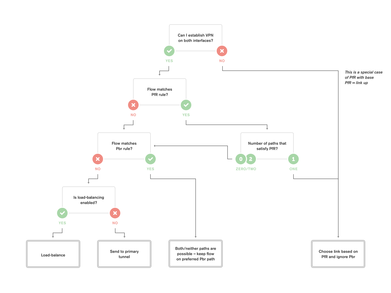
Decision Point 1: Can we establish Tunnels over both uplinks?
The very first evaluation point in SD-WAN traffic flow is whether the WAN Appliance has active AutoVPN tunnels established over both interfaces.
.png?revision=1&size=bestfit&width=860&height=638)
When VPN tunnels are not successfully established over both interfaces, traffic is forwarded over the uplink where VPN tunnels are successfully established.
.png?revision=1&size=bestfit&width=860&height=638)
If we can establish tunnels on both interfaces, processing proceeds to the next decision point.
Decision Point 2: Are performance rules for dynamic path selection defined?
If we can establish tunnels on both uplinks, the WAN Appliance will then check to see if any dynamic path selection rules are defined.
If dynamic path selection rules are defined, we evaluate each tunnel to determine which satisfy those rules.
.png?revision=1&size=bestfit&width=860&height=634)
If only one VPN path satisfies our performance requirements, traffic will be sent along that VPN path. The WAN Appliance will not evaluate PbR rules if only one VPN path meets the performance rules for dynamic path selection.
.png?revision=1&size=bestfit&width=860&height=634)
If there are multiple VPN paths that satisfy our dynamic path selection requirements or if there are no paths that satisfy the requirements, or if no dynamic path selection rules have been configured, PbR rules will be evaluated.
.png?revision=1&size=bestfit&width=860&height=634)
After performance rules for dynamic path selection decisions are performed, the WAN Appliance evaluates the next decision point.
Decision Point 3: Are PbR rules defined?
After checking dynamic path selection rules, the WAN Appliance will evaluate PbR rules if multiple or no paths satisfied the performance requirements.
If a flow matches a configured PbR rule, then traffic will be sent using the configured path preference.
.png?revision=1&size=bestfit&width=860&height=635)
If the flow does not match a configured PbR rule, then traffic logically progresses to the next decision point.
Decision Point 4: Is VPN load balancing configured?
After evaluating dynamic path selection and PbR rules, the WAN Appliance will evaluate whether VPN load balancing has been enabled.
.png?revision=1&size=bestfit&width=860&height=633)
If VPN load balancing has not been enabled, traffic will be sent over a tunnel formed on the primary Internet interface. Which Internet interface is the primary can be configured from the Security & SD-WAN > Configure > SD-WAN & traffic shaping page in Dashboard.
.png?revision=1&size=bestfit&width=860&height=632)
If load balancing is enabled, flows will be load balanced across tunnels formed over both uplinks.
.png?revision=1&size=bestfit&width=860&height=634)
VPN load balancing uses the same load balancing methods as the WAN Appliance's uplink load balancing. Flows are sent out in a round robin fashion with weighting based on the bandwidth specified for each uplink.