
MX75 Hardware Installation Guide
This guide provides instruction on how to install and configure your MX75 series device. This guide also provides mounting instructions and limited troubleshooting procedures. For more MX device installation guides, refer to the MX installation guides section on our documentation website.
Product Overview
The Meraki MX75 is an enterprise security appliance designed for distributed deployments that require remote administration across medium branch environments. It is ideal for network administrators who demand both ease of deployment and a state-of-the-art feature set. The Meraki Dashboard allows for simple and easy deployment of the MX75 with minimal pre-configuration in almost any location.

Features
MX75 provides dedicated WAN uplinks, a single 1GbE SFP port, and 2 RJ45 1GbE ports. The LAN ports include 10 RJ45 1GbE ports. The MX75 is ready for deployment in a variety of enterprise environments. MX75 appliance provides the following features:
|
|
Context and Comparisons
| MX68 | MX75 | MX85 | |
|---|---|---|---|
| # WAN Uplinks | 2 | 3 | 4 |
| Stateful Firewall Throughput | 600 Mbps | 1 Gbps | 1 Gbps |
| Maximum site-to-site VPN Throughput | 300 Mbps | 500 Mbps | 500 Mbps |
| Advanced Security Throughput | 300 Mbps | 800 Mbps | 800 Mbps |
| PoE+ Capabilities | Yes, 2x GbE RJ45 LAN Ports (802.3at) | Yes, 2x RJ45 / 1 Gigabit Ethernet port (LAN) | Yes, 1x RJ45 / 1 Gigabit Ethernet port (WAN) |
| Recommended Device Count | Small branch with up to 50 devices |
Small branch office or retail location with 200 devices |
Small to midsize branch office or retail location with 250 devices |
Physical Specifications
| MX68 | MX75 | MX85 | |
| # WAN Interfaces | 2 | 3 | 4 |
| LAN Interfaces - Dedicated | 10x Dedicated GbE RJ45 | 10x Dedicated GbE RJ45 | 3x Dedicated GbE RJ45 |
| LAN Interfaces - Convertible | 2x Dedicated GbE RJ45 PoE+ | 2x Dedicated GbE RJ45 PoE+ | 1x Convertible LAN/WAN GbE RJ45 |
| Mount Type | Desktop / Wall Mount | Desktop / Wall Mount | Rack Mount |
|
Dimensions (h x d x w) |
1.1 x 5.8 x 11.2 in / 27 x 148 x 284 mm |
1.06" x 5.83" x 11.14" 27 x 148 x 283 mm |
1.7” x 9.8“ x 19” 43.8 x 250 x 484.6mm |
| Weight | 2.46 lb / 1.12 kg | 1.87lb (0.85kg) | 8.2lb (3.7kg) |
| Power Supply | 100W DC (included) | 100W DC (included) |
Internal 100-220V 50/60Hz AC |
| Power Load (idle/max) | 11W / 79W | 12W / 96W | 12W / 55W |
| Operating Temperature |
32°F - 104 °F 0°C - 40°C |
32°F to 113°F (0°C to 45°C) |
32°F to 104°F (0°C to 40°C) |
|
Storage and Transportation Temperature |
-4°F - 158°F -20°C - 70°C |
-4°F - 158°F -20°C - 70°C |
-4°F - 158°F -20°C - 70°C |
| Humidity | 5% to 95% | 5% to 95% | 5% to 95% |
Accessories
| Accessory | Description |
| MA-PWR-CORD-US | 1x AC Power Cable, US plug |
| MA-PWR-CORD-EU | 1x AC Power Cable, EU plug |
| MA-PWR-CORD-UK | 1x AC Power Cable, UK plug |
| MA-PWR-CORD-AU | 1x AC Power Cable, AU plug |
| MA-PWR-100WAC-A | 1x Meraki MX Replacement Power Adapter (MX75) (100 Watts AC) |
Note: Please refer to meraki.com for additional single-mode and multi-mode fiber transceiver modules
Product View and Physical Features
Front Panels
MX75

Status Indicator
The MX75 series devices uses an LED to inform the user of the device's status. LED patterns and their meanings are described below.
|
LED Status |
Meaning |
|
Solid orange |
Power is applied but the appliance is not connected to the Meraki Dashboard |
| Rainbow Colors | The appliance is attempting to connect to Meraki Dashboard |
|
Flashing White |
Firmware upgrade in progress |
|
Solid White |
Fully operational/connected, uplink actively using wired WAN |
| Solid Purple | Fully operational/connected, uplink actively using integrated cellular failover |
Back Panels
MX75

MX75 Back Panel Functions
Additional functions on the back panel are described below, from left to right.
|
USB port |
USB 3.0 port |
|---|---|
| WAN / Internet port | This port provides connectivity to the WAN. |
| LAN ports |
These 10 ports provide connectivity to computers, printers, access points, or Ethernet switches. A steady green LED indicates link speed and flashing amber indicates traffic. |
| Power input | Designed for use only with the unit’s power supply. |
|
Reset button |
Insert a paper clip if a reset is required. Press for 1 second to delete a downloaded configuration and reboot. |
Side Panels
MX75

Bottom Panel
Please note that the serial number is located on the product label at the bottom panel of MX75 devices
Package Contents
In addition to the MX device, the following are provided:
| MX75 |
|---|
| Power Adapter (No Power Cable) |
Safety and Warnings
These operations are to be taken with respect to all local laws. Please take the following into consideration for safe operation:
- Power off the unit before you begin. Read the installation instructions before connecting the system to the power source.
- Before you work on any equipment, be aware of the hazards involved with electrical circuitry and be familiar with standard practices for preventing accidents.
- Read the mounting instructions carefully before beginning installation. Failure to use the correct hardware or to follow the correct procedures could result in a hazardous situation to people and damage to the system.
- This product relies on the building’s installation for short-circuit (overcurrent) protection. Ensure that the protective device is rated not greater than: 15 A, 125 Vac, or 10A, 240 Vac.
- Please only power the device with the provided power cables to ensure regulatory compliance.
Pre-install Preparation
You should complete the following steps before going on-site to perform an installation.
Configure your Dashboard Network
The following is a brief overview only of the steps required to add an MX to your network. For detailed instructions about creating, configuring and managing Meraki networks, refer to the online documentation (documentation.meraki.com).
- Login to http://dashboard.meraki.com. If this is your first time, create a new account.
- Find the network to which you plan to add your MX or create a new network.
- Add your MX to your network. You will need your Meraki order number (found on your invoice) or the serial number of each MX, which looks like Qxxx-xxxx-xxxx, and is found on the bottom of the unit. You will also need your Enterprise license key, which you should have received via email.
- Go to the map / floor plan view and place each MX on the map by clicking and dragging it to the location where you plan to mount it.
Check and Set Firmware
To ensure your MX performs optimally immediately following installation, it is recommended that you facilitate a firmware upgrade prior to mounting your MX.
- Attach your MX to power and a wired Internet connection.
- The MX will turn on and the power LED will glow solid orange.
- If the unit requires an upgrade, the power LED will begin blinking white until the upgrade is complete, at which point the LED will turn solid white. You should allow at least a few minutes for the firmware upgrade to complete, depending on the speed of your internet connection.
Check and Configure Upstream Firewall Settings
If an upstream firewall is already in place, it must allow outgoing connections on particular ports to particular IP addresses. The most current list of outbound ports and IP addresses for your particular organization can be found on the firewall configuration page in your dashboard.
Installation Instructions
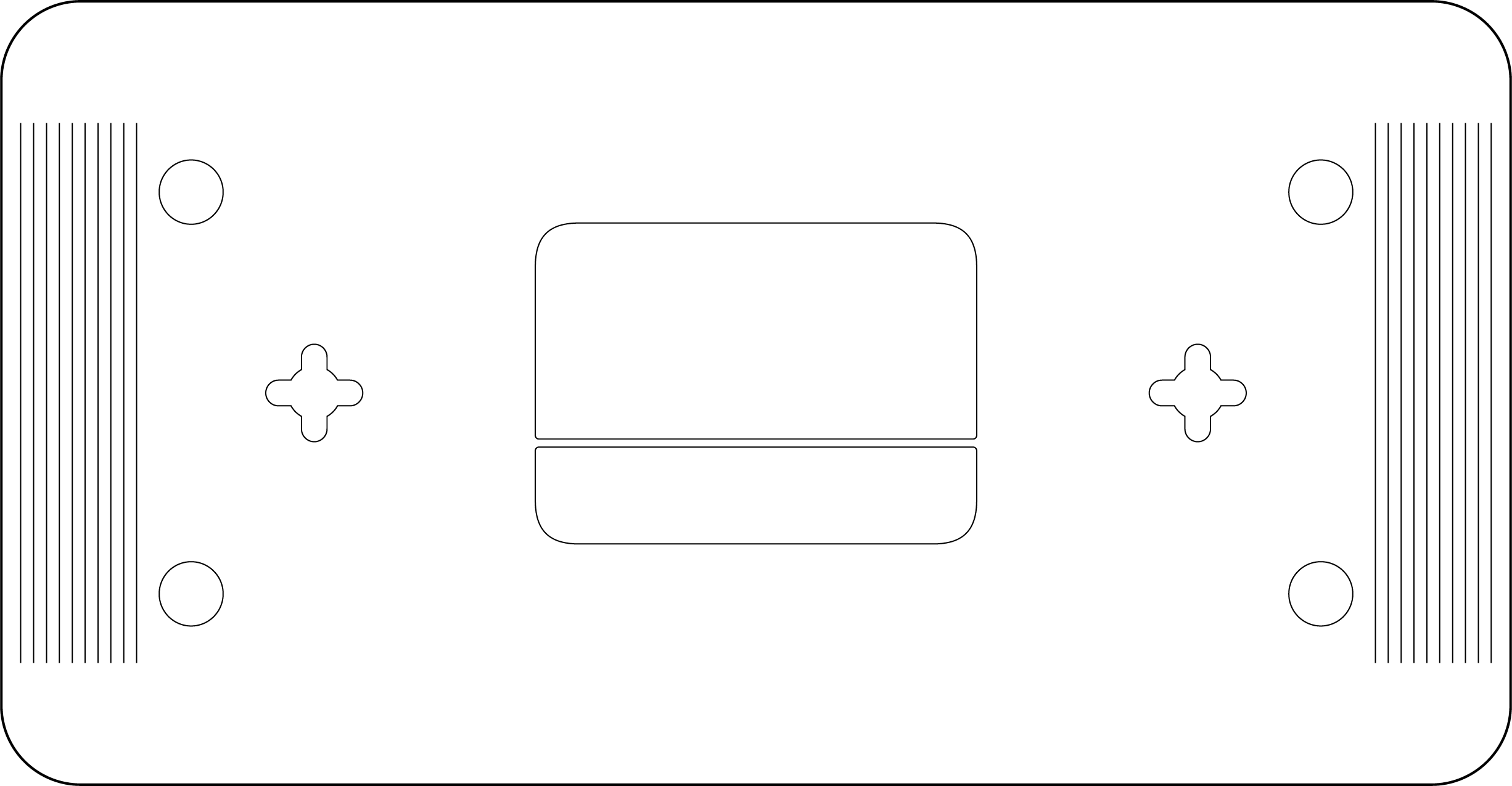
Mounting Recommendations
You can mount the appliance on a drywall surface, either vertically or horizontally. The distance between the holes you drill should be 5-1/8 inches (13 cm). The fan grills for the MX75 are located at the bottom of the chassis.
Note: Please make sure there are no blockages or obstructions within one inch of the top of the chassis or within 0.5 inches of the sides so that nothing interferes with cooling.
Connecting to WAN
All Meraki MX devices must have an IP address. This section describes how to configure your local area network before you deploy it. A local management web service, running on the appliance, is accessed through a browser running on a client PC. This web service is used for configuring and monitoring basic ISP/WAN connectivity.
Setting up a Static IP Address
Do the following to configure basic connectivity and other networking parameters:
- Using a client machine such as a laptop, connect to one of the LAN ports of the MX.
- Using a browser on the client machine, access the appliance's built-in web service by browsing to http://setup.meraki.com. (You do not have to be connected to the Internet to reach this address)
- Click Uplink configuration under the Local status tab. The default credentials use the device serial number as the username, with a blank password field.
- Choose Static for the IP Assignment option.
- Enter the IP address, subnet mask, default gateway IP and DNS server information.
Setting up a DHCP IP Address
By default all MX devices are configured to DHCP from upstream WAN / ISP servers. Simply plug the MX's WAN / Internet port to your upstream circuit and wait a few minutes for the unit to negotiate a DHCP address.
Additional Settings
Setting VLANs
If your WAN uplink is on a trunk port, choose VLAN tagging > Use VLAN tagging and enter the appropriate value for VLAN ID for your network.
Setting up a Secondary WAN Interface on the MX75
MX75 comes with three dedicated Internet ports, which are configured under Security & SD-WAN > Monitor > Appliance Status in the Uplink tab.
By default on the MX75, only two of the three WAN ports can be utilized at once. You can read more about WAN behavior on the MX75 in WAN Behavior on MX75/85/95/105.
Additionally, three WAN interfaces can be utilized on the MX75 using MultiWAN backup interface.
Setting PPPoE
PPPoE authentication may be required if you are connecting MX device to a DSL circuit. You need to know your authentication option and credentials (supplied by your ISP) in order to complete these steps.
- Choose Connection Type > PPPoE.
- Select your Authentication option.
- If you select Use authentication, enter appropriate values for Username and Password.
Web Proxy Settings
These settings take effect if the MX device has to fall back to using HTTP to contact the Cloud Controller. By default, web proxy is disabled. To enable web proxy, do the following:
- Choose Web proxy > Yes.
- Enter values as appropriate for Hostname or IP and Port.
- If you require authentication, choose Authentication > Use authentication, and enter appropriate values for Username and Password.
Configuring Physical Link Settings
To configure physical link settings on the Ethernet ports, click Local status > Ethernet configuration. You can enable half duplex, full duplex, and autonegotiation, as well as set 10/100/1000-Mbps data rates.
Basic Troubleshooting
The following steps can be used for troubleshooting basic connectivity issues with your MX.
- Reset the MX
- Factory reset the MX by holding the factory reset button for 10-15 seconds
- Try switching cables, or testing your cable on another device
Reference https://documentation.meraki.com/MX for additional information and troubleshooting tips.
If you are still experiencing hardware issues, please contact Cisco Meraki support by logging in to dashboard and using the Help option near the top of the page, then opening and email case or calling using the contact information on that page.
Warranty
MX Warranty coverage periods are as follows:
|
Product |
Warranty Period |
Warranty Information |
|---|---|---|
|
MX75 |
Lifetime |
Full lifetime hardware warranty with next-day advanced replacement included. |
|
MX75 Accessories |
1 Year |
The following are considered accessories: SFP Modules, all mounting kits and stands, interface modules, additional power cords |
Additional warranty information can be found on the Return Policy and Requesting a RMA page of the Cisco Meraki website.
If your Cisco Meraki device fails and the problem cannot be resolved by troubleshooting, contact support to address the issue. Once support determines that the device is in a failed state, they can process an RMA and send out a replacement device free of charge. In most circumstances, the RMA will include a pre-paid shipping label so the faulty equipment can be returned.
Support and Additional Information
If issues are encountered with device installation or additional help is required, contact Meraki Support by logging in to dashboard.meraki.com and opening a case by visiting the Get Help section.
- The equipment is intended for industrial or other commercial activities.
- The equipment is used in areas without exposure to harmful and dangerous production factors, unless otherwise specified in the operational documentation and/or on the equipment labeling.
- The equipment is not for domestic use. The equipment is intended for operation without the constant presence of maintenance personnel.
- The equipment is subject to installation and maintenance by specialists with the appropriate qualifications, sufficient specialized knowledge, and skills.
- Rules and conditions for the sale of equipment are determined by the terms of contracts concluded by Cisco or authorized Cisco partners with equipment buyers.
- Disposal of a technical device at the end of its service life should be carried out in accordance with the requirements of all state regulations and laws.
- Do not throw in the device with household waste. The technical equipment is subject to storage and disposal in accordance with the organization's disposal procedure.
- The equipment should be stored in its original packaging in a room protected from atmospheric precipitation. The permissible temperature and humidity ranges during storage are specified in the Operation (Installation) Manual.
- Transportation of equipment should be carried out in the original packaging in covered vehicles by any means of transport. The temperature and humidity during transportation must comply with the permissible established ranges of temperature and humidity during storage (in the off state) specified in the Operation Manual (Installation)
For additional information on Meraki hardware and for other installation guides, please refer to documentation.meraki.com.