
vMX Setup Guide for NFVIS
Overview
The following guide will serve as a living document for deploying and troubleshooting the vMX solution on Cisco's Enterprise NFV Infrastructure Software (NFVIS) platform. After completing these steps outlined in this document, you will have a virtual MX appliance running on a UCS compute platform in your own datacenter leveraging the NFVIS software. CSP UCS hardware is the recommended UCS platform for running NFVIS and the Meraki vMX.
NFVIS Architecture
The NFVIS platform operates on Cisco UCS hardware and can run multiple Meraki vMX's on top. Additionally, many other Cisco and KVM-based VNF's will also run on the NFVIS platform as well. The following diagram illustrates the entire hardware and software stack of the platform.
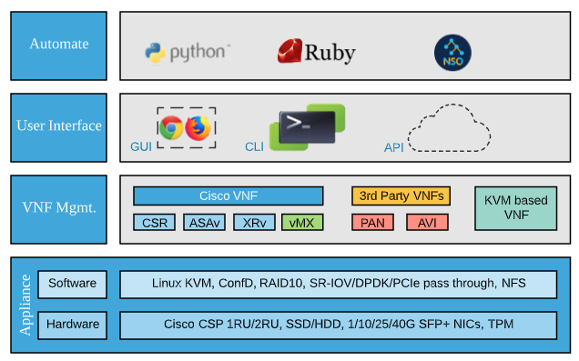
The virtualization stack is comprised of a Cisco CSP UCS at the hardware level and on top of that it runs the KVM hypervisor and NFVIS software for VNF lifecycle management.
NFVIS Features Unsupported for vMX
The following NFVIS features are not supported for the Meraki vMX VNF and will not work within NFVIS.
- Meraki vMX VM's cannot be exported using the export/backup tool (other VM types can be)
- Meraki vMX VM's are not included in full system backups (other VM types are included)
- The Meraki vMX package can only be registered/deployed on UCS-C/CSP hardware and not on other NFVIS platforms such as UCS-E or ENCS
- The Meraki vMX package cannot be registered or deployed on NFS storage. Only local storage is supported.
Supported UCS Hardware
While the NFVIS software can be installed on any Cisco UCS C-Series M5 hardware (for trial/demo purposes), the supported and validated platform of choice for both NFVIS and Meraki is the Cisco CSP UCS hardware. CSP (cloud service platform) is a turnkey, validated UCS M5 which can be shipped with NFVIS software already installed and ready to go from factory. The following table outlines the different CSP models supported for the Meraki vMX.
|
|
CSP 5216 |
CSP 5228 |
CSP 5444 |
CSP 5456 |
|
Rack Size |
1RU |
2RU |
||
|
CPU Cores |
16 |
28 |
44 |
56 |
|
PCIe NIC Slots |
2 |
6 |
||
|
Disk Slots |
8 |
24 |
||
|
Power 2 slots (AC) |
1540W (2x770) |
2100W (2x1050) |
||
|
PCIe NIC Slots |
2 |
6 |
||
|
Minimum Memory |
64GB |
96GB |
128GB |
192GB |
|
On Board NICs (LOM) |
2 x10 GbE SFP+ (Eth0-1/Eth0-2) |
|||
|
I-350 (4x1GB RJ45) |
works but not currently supported for vMX due to the low performance of the NIC |
|||
|
X-520 (2x10GbE SFP+) available |
Yes (recommended NIC for vMX) |
|||
|
X-710(4 x 10GbE SFP+) available |
works but not currently supported for vMX due to performance concerns |
|||
|
XL-710 (2 x 40GbE QSFP) available |
not currently supported for vMX |
|||
| SFP Module |
CSP-SFP-1WS/LR (orderable with the CSP hardware) MA-CBL-TA-1M/3M (Meraki twinax) *Meraki fiber SFP modules are not currently compatible with the Intel X-520 NIC and the CSP-SFP-1WS/LR modules above are not currently supported by the Meraki switches. We recommend using the Meraki twinax cables when using Meraki MS switches or if fiber is needed then we recommend the CSP-SFP modules and non-Meraki switches. **In testing, the CSP-SFP modules did not work with the MS425 switch but do work with the MS350 series switches however the only officially supported SFP modules for Meraki switches are those documented here. |
|||
|
Supported Disks |
1.2TB HDD in RAID |
|||
|
DC Power available |
Yes |
|||
| Reference BOMs | Reference BOMs | |||
NFVIS Sizing Considerations
|
CSP-5216 UCS |
CSP-5228 UCS |
CSP-5444 UCS |
CSP-5456 UCS |
|
|
Total Cores |
16 |
28 |
44 |
56 |
|
NFVIS-OS Cores |
2 |
2 |
2 |
2 |
|
NFVIS-OS Memory |
16 GB |
|||
|
Max vMX-M/L |
7 |
13 |
21 |
27 |
|
Max vMX-S |
14 |
26 |
42 |
54 |
|
Max Aggregate VPN Throughput (using vMX-L instances) |
7 Gbps |
13 Gbps |
21 Gbps |
27 Gbps |
| Max Aggregate VPN Tunnels (using vMX-L instances) | 7,000 | 13,000 | 21,000 | 27,000 |
|
Intel X-520 Cards (2 x 10GB SFP+ Ports) |
1 |
1 |
2 |
2 |
|
Minimum 16GB Memory DIMMs |
4 |
6 |
8 |
12 |
|
Storage |
4 x 1.2 TB 10K SAS Drives |
|||
Please refer to the UCS M5 Memory Planning spec sheet for more details around memory planning.
Per the memory spec sheet above (page 14) 5, 7, 9, 10, 11 DIMMs per CPU is not recommended for best memory performance. This is why we suggest at least 12 x 16GB DIMMs for the 5456 model (6 DIMMs per CPU socket).
Additionally, for optimal memory performance having more smaller size DIMMs is better than fewer larger size ones. For example, if you need 128GB of memory for your CSP then it's better to use 8 x 16GB DIMMs instead of 4 x 32GB DIMMs
vMX Profiles for NFVIS
| vMX-S | vMX-M | vMX-L | |
|
Throughput |
200Mbps |
500Mbps |
1Gbps |
|
Number of Tunnels (site-to-site VPN) |
50 |
250 |
1,000 |
| vMX CPU Cores | 1 | 2 | 2 |
| vMX Memory | 2GB | 2GB | 4GB |
For more detailed information please refer to the vMX datasheet.
Ordering Trial/Demo Hardware
To order demo/trial UCS/CSP hardware please work with your Meraki account teams who will be able to facilitate this via Cisco's demo depot program.
NFVIS Setup
Hardware Installation
For setting up your UCS hardware including interfaces and connectivity please refer to the Cisco Cloud Services Platform 5000 Hardware Installation Guide.
For assistance or issues in setting up your CSP UCS appliance please open a case with Cisco TAC online here or call 800-553-2447 (USA/Canada) or click here for worldwide phone numbers.
Port(s) 3 below are used for NFVIS management and should be cabled to the management network
Port 5 is used for UCS CIMC Management and should be cabled to the management network
PCIe 1 and 2 slots will be used for VM traffic and should be cabled to the network/VLANs where the vMXs will connect

|
1 |
Modular LAN-on-motherboard (mLOM) card bay (x16 PCIe lane) |
7 |
Rear unit identification button/LED |
|
2 |
USB 3.0 ports (two) |
8 |
Power supplies (two, redundant as 1+1) |
|
3 |
Dual 1-Gb/10-Gb Ethernet ports (LAN1 and LAN2) The dual LAN ports can support 1 Gbps and 10 Gbps, depending on the link partner capability. |
9 |
PCIe riser 2/slot 2 (x16 lane) Includes PCIe cable connectors for front-loading NVMe SSDs (x8 lane) |
|
4 |
VGA video port (DB-15 connector) |
10 |
PCIe riser 1/slot 1 (x16 lane) |
|
5 |
1-Gb Ethernet dedicated management port |
11 |
Threaded holes for dual-hole grounding lug |
|
6 |
Serial port (RJ-45 connector) |
- |
NFVIS Installation
Please refer to the NFVIS installation guide for the most up to date information.
If you chose the NFVIS software option while ordering your CSP UCS hardware, then NFVIS will be installed from factory and ready to go when you receive the hardware. Please refer to the "Upgrading NFVIS" section below to upgrade your NFVIS to the latest version.
The Meraki vMX is only supported on NFVIS 4.5.1* and higher versions and ONLY on UCS-C/CSP hardware. ENCS, UCS-E and other platforms which NFVIS runs on are not currently supported and the Meraki vMX for NFVIS package will not work on lower NFVIS versions or other hardware platforms.
* For beta testing NFVIS version 4.4.1 can be used
UCS-C series devices have to be configured with a RAID disk group before installing NFVIS. UCS-C supports only single RAID disk group for fresh installation.
Procedure
| Step 1 | Download the latest NFVIS installation ISO here | ||
| Step 2 |
Log in to CIMC. The recommended CIMC version for USC-C Series Servers and Cisco CSP platforms is 3.0(3c) or later version. Please refer to the NFVIS release notes for the latest. Every UCS comes with an embedded interface called the Cisco Integrated Management Console (CIMC). From this interface you can view the overall health of the server including overall CPU utilization (this information is also available within the NFVIS UI/API as well). When this hardware utilization starts to surpass the ~80% mark for sustained periods of time it will likely be time to begin procuring another box to scale out further on. You can also launch a KVM/Java console from this interface to interact with the server as if you had a monitor plugged in locally and you can enable SNMP and other monitoring to alert you about various system health metrics. The default log in credentials are Username: admin and Password: password (you will be prompted to change the password after logging in the first time).
|
||
| Step 3 |
To launch the KVM Console, Select Launch KVM from the CIMC homepage. You can choose Java or HTML based KVM. It is recommended to use HTML based KVM. Ensure that the pop-up blocker is disabled as KVM Console will open in a separate window. |
||
| Step 4 |
To map virtual devices from the KVM Console:
|
||
| Step 5 |
To configure boot order:
|
||
| Step 6 |
Power cycle the server to start the installation:
When the server reboots, the KVM console automatically installs Cisco Enterprise NFVIS from the virtual CD/DVD drive. The entire installation might take 30 minutes to one hour to complete. During the install process it may look like nothing is happening but the install procedure is executing. |
||
| Step 7 |
After the installation is complete, the system automatically reboots from the hard drive. Log into the system when the command prompt nfvis login is displayed after the reboot. Use admin as the login name and Admin123# as the default password.
|
||
| Step 8 |
Verify the installation using the System API, CLI, or by viewing the system information from the Cisco Enterprise NFV portal. |

NFVIS Upgrade
Please refer to the NFVIS upgrade guide for the most up to date information.
The Meraki vMX is only supported on NFVIS 4.5.1* and higher versions. The Meraki vMX for NFVIS package will not work on lower NFVIS versions. NFVIS dos not support in-place downgrades. If you wish to downgrade to an older NFVIS release you must do a complete re-install.
* For beta testing NFVIS version 4.4.1 can be used
Your Cisco CSP UCS hardware comes pre-installed with NFVIS. Follow the steps below to upgrade it to the latest version.
The Cisco Enterprise NFVIS upgrade image is available as a .nfvispkg file. Currently, downgrade is not supported. All RPM packages in the Cisco Enterprise NFVIS upgrade image are signed to ensure cryptographic integrity and authenticity. In addition, all RPM packages are verified during Cisco Enterprise NFVIS upgrade.
Procedure
| Step 1 | Download the latest NFVIS upgrade NFVISPKG here |
| Step 2 |
Log in to the NFVIS UI in your browser. |
| Step 3 |
Navigate to Host > Upgrade and click the upload button ( |
| Step 4 |
Once uploaded, use the Select Upgrade dropdown box to choose the upgrade file you just uploaded. Choose to Upgrade now or Upgrade later. Click the Start Upgrade button. You will see the following message in your browser while the upgrade takes place. Upgrades can take anywhere from 30 - 60 minutes to complete. The host will reboot as well when the upgrade is complete.
|
| Step 5 |
Verify the upgrade using the System API, CLI, or by viewing the system information from the Cisco Enterprise NFV portal. |


Post-Install Configuration
Oversubscription
NFVIS and Meraki do not currently support oversubscription of low-latency VMs such as the vMX. Oversubscription is often desired in virtualized environments when operating application servers (ex. web server, dev server, etc) because applications are very bursty in nature. However, when running virtualized network functions such as a vMX it is not ideal as performance cannot be guaranteed when oversubscribing since you are sharing CPU cycles with other VMs.
NFVIS does allow oversubscription of non-low-latency VM's but this is not enabled or supported in the vMX NFVIS package.
Hyperthreading
In CSP UCS hardware platforms, hyperthreading is disabled by default in the BIOS. This is to ensure higher and more deterministic throughput. If hyperthreading is enabled, you could end up with multiple VNF's sharing CPU time on the same physical core (even though they are operating on different threads on that core) which can lead to contention between the instances and subsequently lower performance.
Meraki does not currently support vMX running on hyperthread-enabled platforms
Enable SR-IOV
The below procedure will guide you to enable SR-IOV on your NFVIS platform. While the Meraki vMX does work with the virtio/DPDK bridges (WAN-BR/LAN-BR) these are not recommended as they will result in lower performance of the vMX and have a maximum throughput of ~8Gbps for the whole bridge (this means 8 x vMX-L running at 1Gbps will max out the network throughput on the box).
Procedure
| Step 1 |
Log in to the NFVIS UI in your browser. |
| Step 2 |
Navigate to VM Life Cycle > Networking. Under the SRIOV Networks section change the Show dropdown to All then select all SRIOV interfaces that exist already and delete them ( NOTE: We will not enable SR-IOV on Eth0-1/Eth0-2 since these are the on-board management interfaces and we recommend not running vMXs from these interfaces (keep management traffic segmented from VM traffic) so we will just clean this up first. We need to delete all other SRIOV networks on the other NICs so we can enable more of the sub-interfaces in the next step. |
| Step 3 |
Navigate to Host > Interfaces and click the edit button ( |
| Step 4 |
The Intel X-520 cards support 61 VF's (sub-interfaces) for VMs to connect to. By default, only 4 are enabled in NFVIS. To enable more VF's we first need to disable SR-IOV. Change SRIOV Status to disabled. Click Submit.
Once you click submit you should see the following message after a few seconds:
|
| Step 5 |
Next click the edit button next to the interface again. Change SRIOV Status to Enabled and enter 61 in the SRIOV Number of VFs textbox. Leave the Switchmode field empty. Click Submit.
|
| Step 6 |
Repeat steps 3-5 for the other NIC's you wish to enable SRIOV on. |
| Step 7 |
Navigate to VM Life Cycle > Networking and click the plus icon (
When using SRIOV, if you want vMXs to be on different VLANs you cannot set the VLAN tag on the vMX uplink config but instead need to set the VLAN on the SRIOV VF here. |
| Step 8 | Repeat step 7 for the other NICs which you want to create SRIOV sub-interfaces for. |
 ).
).  ) next to the Intel X-520 NIC you wish to use for vMX traffic (NOTE: Do not modify Eth0-1/Eth0-2 as that is the management/onboard NIC and should be used for only management traffic, not VM traffic). Eth1-1/1-2 or Eth2-1/2-2 will be your PCI X-520 card interfaces.


 ) next to SRIOV Networks. In the modal that expands at the top of the page, select the interface which you want to create the SRIOV VF's for and enter the range 1-61 to create all 61 VF's for the interface. Set them to trunk or access mode depending on the desired option (setting to access mode allows you to define a VLAN for this VF) and click Submit.
Registering the Meraki vMX NFVIS Package
The following procedure walks through uploading and registering the Meraki vMX NFVIS package.
The Meraki vMX is only supported on NFVIS 4.5.1* and higher versions and ONLY on UCS-C/CSP hardware. ENCS, UCS-E and other platforms which NFVIS runs on are not currently supported and the Meraki vMX for NFVIS package will not work on lower NFVIS versions or other hardware platforms.
* For beta testing NFVIS version 4.4.1 can be used
Procedure
| Step 1 |
Log in to the NFVIS UI in your browser. |
| Step 2 |
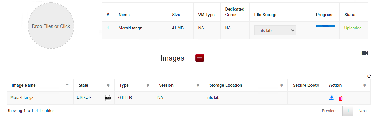
Navigate to VM Life Cycle > Image Repository. Select the upload button next to Images ( The package that you upload must be named Meraki.tar.gz just how it was named when downloaded from Cisco. The datastore selected must be datastore1. Deploying the package as a different name or on a different datastore (ex. NFS) will result in an error
|
| Step 3 |
Once the image uploads and successfully registers the Images table should show the Meraki.tar.gz option with an Active state. Three Profiles (vMX-S, vMX-M and vMX-L) are also created as part of the image registration. |
| Troubleshooting |
The Meraki vMX package must be named Meraki.tar.gz just as how it was when downloaded from Cisco. If the name is changed, the registration will fail and you will see the following error
In the log you will see the following error: VIM Error Code for creating image object: 500, VIM Response: "Could not untar: data/intdatastore/uploads/test.tar.gz \ngzip: stdin: not in gzip format\ntar: Child returned status 1\ntar: Error is not recoverable: exiting now\n"
|
| Troubleshooting |
The Meraki vMX cannot be registered on NFS storage. if you attempt to register it on NFS using the upload tool you will see the following error:
In the log you will also see the following error: VIM Error Code for creating image object: 500, VIM Response: "Datastore lab invalid for Meraki vMX. Only local storage supported" |
 ). Browse to and select the Meraki.tar.gz vMX NFVIS package you downloaded from software.cisco.com. Choose datastore1(internal) for File Storage and click Start.

Creating a Meraki vMX on NFVIS
The following procedure will guide you through creating a vMX in the Meraki Dashboard and instantiating it on NFVIS.
Licensing
The Meraki Dashboard will require a VMX-S, VMX-M or VMX-L license to be added before you are able to continue deploying a vMX. If you do not have access to a VMX-S, VMX-M or VMX-L license, please reach out to your Meraki Reseller or Sales Rep.
Generate a vMX Node
First we need to generate a vMX node inside the Meraki dashboard which we will then instantiate on NFVIS. Begin by creating a new Security Appliance network in your organization. This guide will walk you through creating a new network in the Meraki Dashboard.
Once you have created the network and added the appropriate license you will be able to deploy a new vMX instance in your network by navigating to Security & SD-WAN > Monitor > Appliance Status and clicking on the relevant 'Add VMX' button:

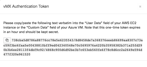
Generate Auth Token
After you add the new vMX to your network, navigate to Security & SD-WAN > Monitor > Appliance Status and select “Generate authentication token” towards the bottom left of the page to generate and copy the token. This will be used in our day0 configuration below.
The authentication token must be entered into the local status page within 1 hour of generating it. If it has been more than 1 hour then a new token must be generated.

Instantiate the vMX on NFVIS
The following procedure will guide you through creating your vMX on NFVIS.
Procedure
| Step 1 |
Log in to the NFVIS UI in your browser. |
| Step 2 |
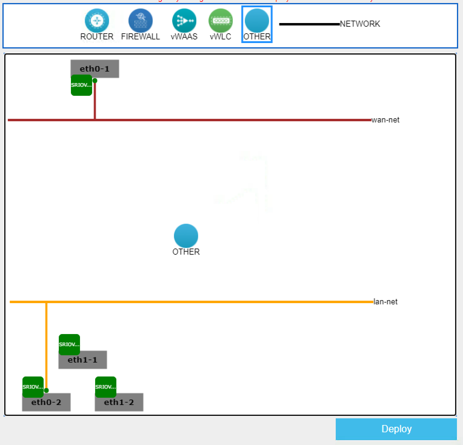
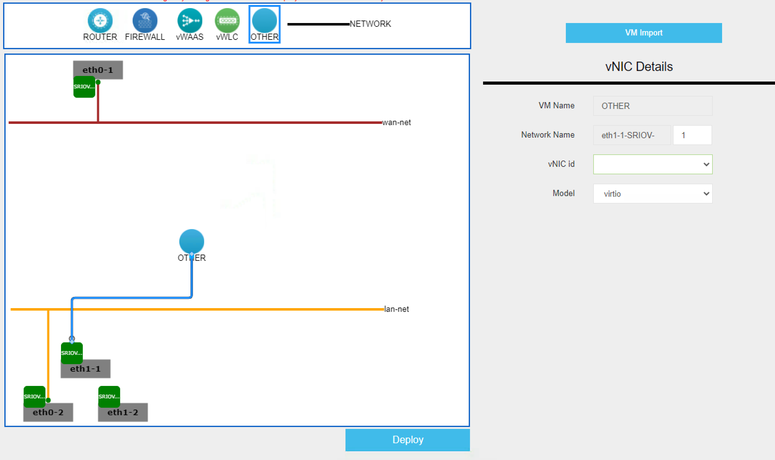
Navigate to VM Life Cycle > Deploy. Drag an OTHER object on to the network layout screen.
|
| Step 3 |
Click the new OTHER object and drag a link to the NIC of choice. Click the newly created link and enter the desired SRIOV VF number in the Network Name on the vNIC Details on the right hand modal that opens. The vNIC id can be left as 0 or blank and Model as VIRTIO.
|
| Step 4 |
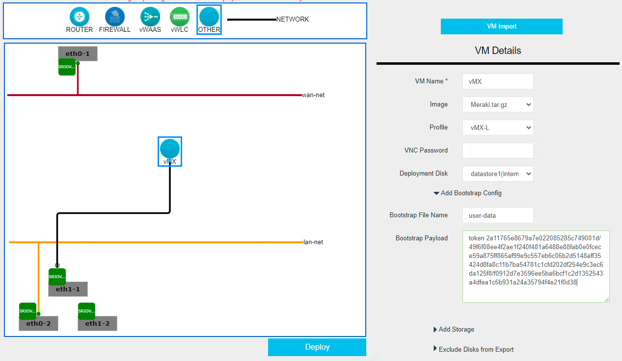
Click the OTHER object again and complete the VM details in the modal on the right.
|
| Step 5 | Click the Deploy button to deploy th vMX instance. |
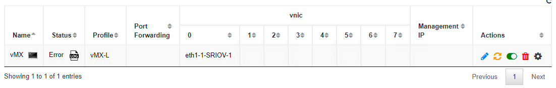
| Step 6 |
Navigate to VM Life Cycle > Manage and click on the console button next to the vMX name ( If the Status says Active check the vMX console for any errors during bootstrapping. Refer to the Troubleshooting section below for error codes and their meanings. If the Status says ERROR, click the Log button (
|
| Step 7 | Follow the steps outlined in this guide to configure the vMX as a one-armed concentrator. |
| Troubleshooting |
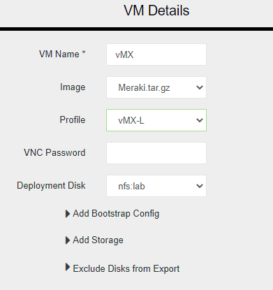
Deploying a vMX with a Deployment Disk location of NFS storage (see image below) is not supported. Only local storage (datastore1) is supported.
If you attempt to deploy a vMX on an NFS storage, the deployment will fail. You will see the following status under VM Life Cycle > Manage for the instance:
In the log you will see the following error message: VIM Error Code for creating image object: 500, VIM Response: "Datastore lab invalid for Meraki vMX. Only local storage supported" |
 ) to open a console to the vMX.
  ) in the status field to see why the error occurred.
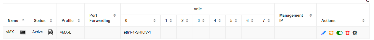
High Availability
The vMX does not currently support dual WAN's or HA (VRRP) like a physical MX does. Additionally, above we recommended using SR-IOV for maximum performance however this means that a VM is bound to a specific interface and there is no ability to use LACP with SR-IOV to accommodate link failure. As such, our recommended failover model is DC-DC failover by deploying a second vMX on a second UCS/NFVIS platform. This way each branch will have a tunnel to each vMX so if a given vMX (or it's uplink) goes down, the branch will maintain VPN connectivity.
Please refer to this document for setting up DC-DC failover.
Troubleshooting
The most common problem people face when deploying a vMX is getting it provisioned and online in their Meraki dashboard in the first place. New troubleshooting/diagnosis messages have been added to the vMX console screen so you can identify what went wrong during the provisioning process.
When a vMX is deployed the following steps will happen during its initial provisioning process:
- Connect to Network
- Obtain user-data (vMX auth token)
- Authenticate with dashboard (using auth token)
- Connect to Dashboard
Connect to Network
When a vMX first connects to a network it will do so via DHCP unless a static IP config is provided in the user-data. Once a vMX connects to dashboard (step 4 above) then a static IP can be applied through dashboard just as it can with any Meraki product.
NOTE: NFVIS is the only platform that currently supports static network configuration via user-data for the initial vMX provisioning process (pre-dashboard checkin). Public cloud environments such as AWS, Azure, GCP and Alicloud rely on DHCP from their VPC.
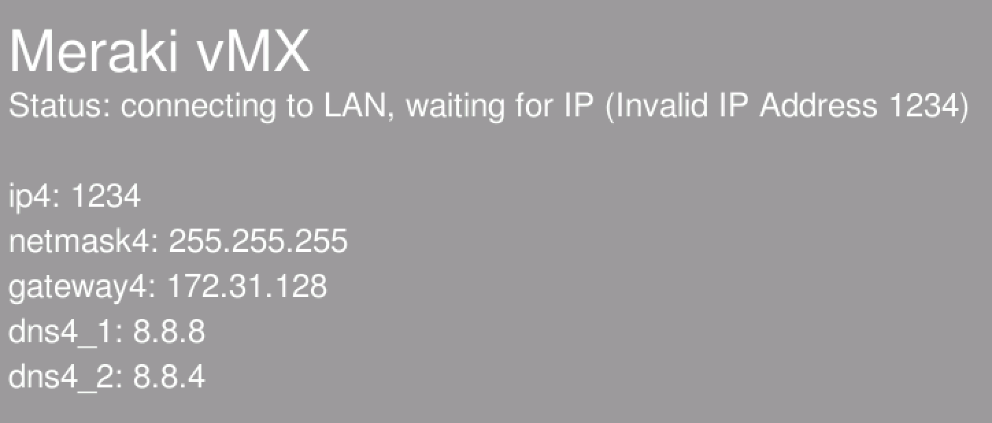
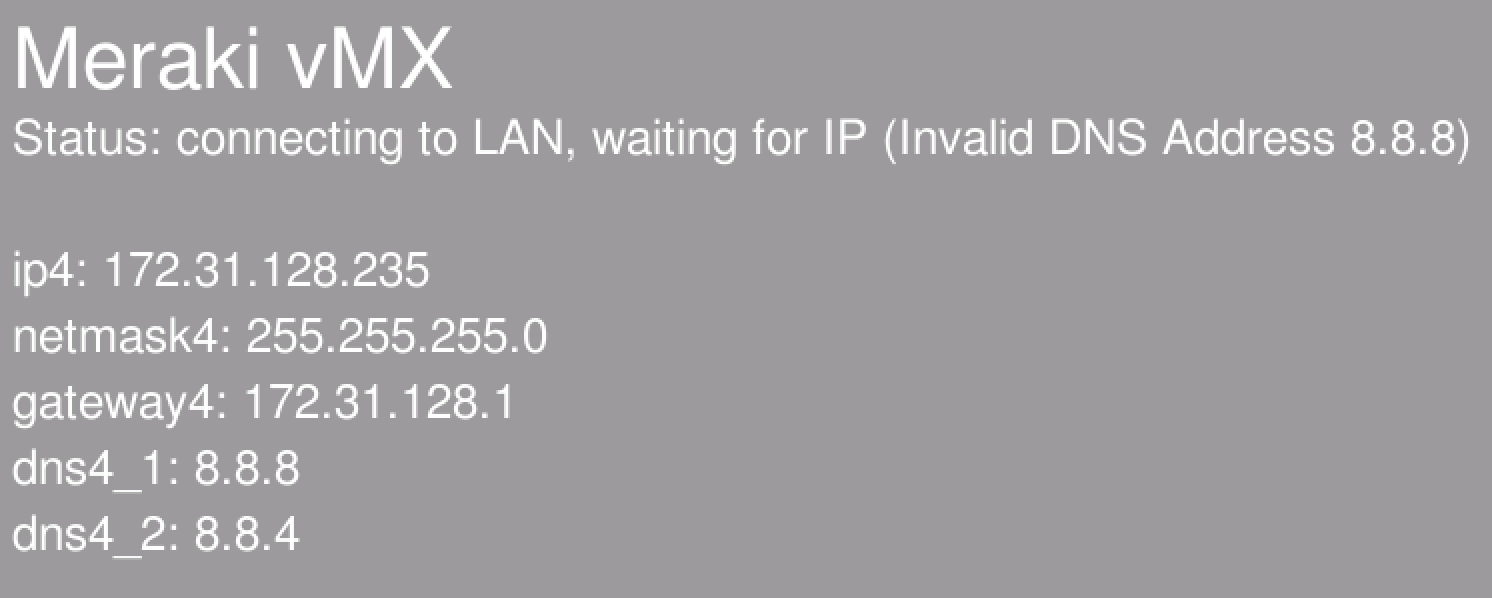
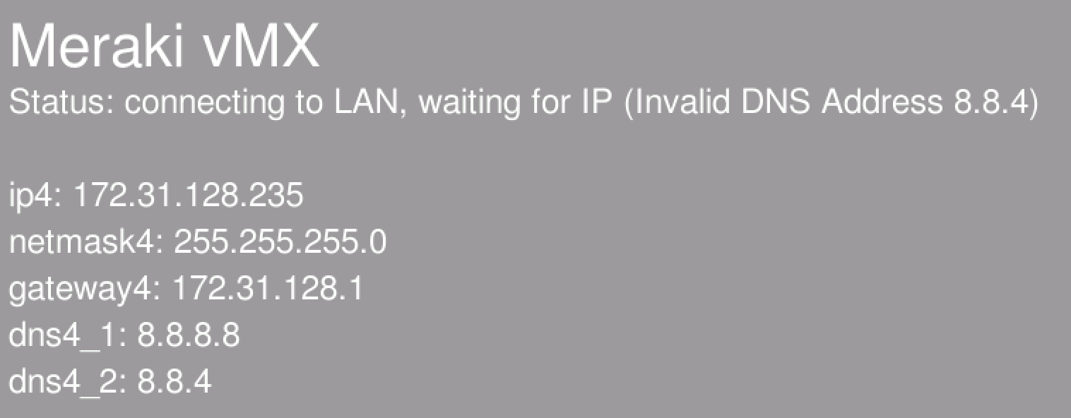
Please see the vMX Deployment section above for providing static IP information via user-data. If static network addressing is provided via the user-data, it will be displayed on the vMX console as well as seen below.
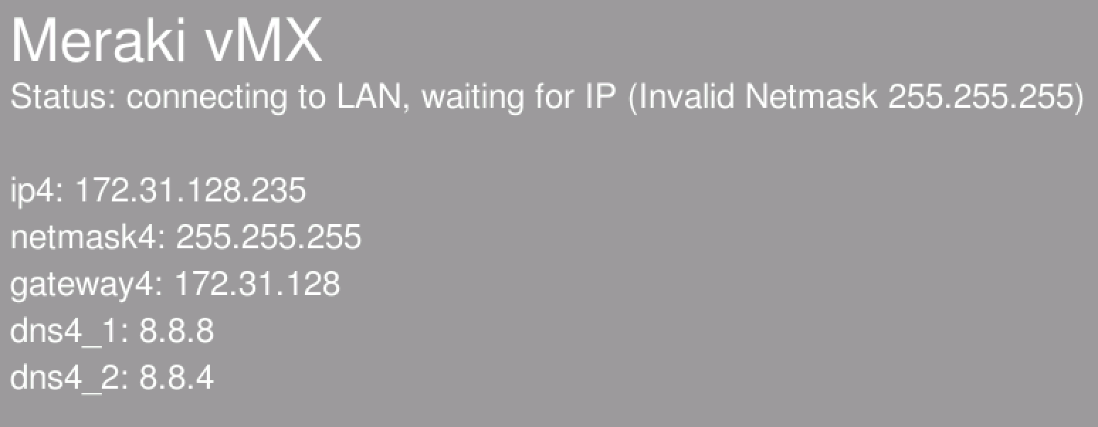
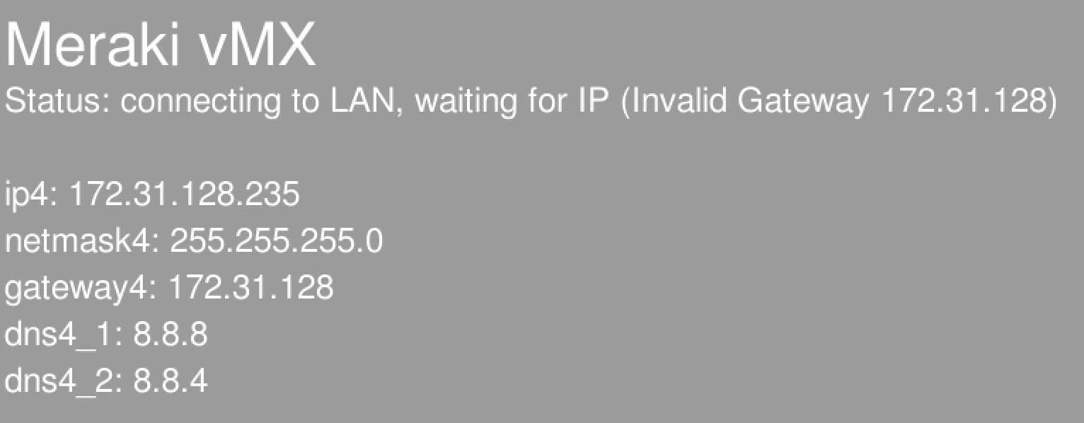
The following errors will be displayed on the vMX console if incorrect network configuration is provided.
Invalid IP Address
Invalid Subnet Mask
Invalid Default Gateway
Invalid DNS
Obtain User-Data & Authenticate to Dashboard
Once a vMX has successfully connected to a network, it will then attempt to obtain its user-data (vMX auth token). There are different user-data mechanisms in each platform that the vMX currently runs on to provide the token to the vMX. In AWS, Azure, GCP and Alicloud there are user-data fields in the VM config where this can be provided. In NFVIS we use the user-data mechanism to get this token to the vMX.
NOTE: Unlike the network config above, the token is not displayed on the console for security and usability reasons (the token is a very long string that is meaningless to anyone looking at it). If you see a token value on the console it means that the token was not provided in the format "token <token>" (note that token should be lowercase).
Token Expired
vMX auth tokens have a lifetime of only 1 hour for security purposes. If you see the following message on your vMX console it means the token you provided is no longer valid. Please generate a new one in dashboard, update the Day0 config and restart your vMX. The vMX will attempt to authenticate against dashboard with the provided token 3 times. After 3 failures, the provisioning process stops and the "provisioning failed" message is displayed.

Invalid Token
If the token provided is incorrect in any way the "invalid token" message is displayed on the console.

Unable to reach Meraki Dashboard
If the vMX is unable to reach dashboard on TCP port 7734 then the initial provisoning phase will fail and an "Unable to reach Meraki Dashboard" message will be displayed on the console. Please refer to this document on the correct ports/IP's that need to be opened for Meraki Dashboard communication.

No Add vMX Button
When navigating to Security & SD-WAN > Monitor > Appliance Status, if there is no "Add vMX" button please ensure the following two conditions are met:
- You have available vMX licenses in your license pool
- Your organization license status is not expiring in <30 days (yellow warning at the top of the Organization > Configure > License Info page)
Key Concepts
Before deploying a virtual MX, it is important to understand several key concepts.
Concentrator Mode
All MXs can be configured in either NAT or VPN concentrator mode. There are important considerations for both modes. For more detailed information on concentrator modes, click here.
One-Armed Concentrator
In this mode, the MX is configured with a single Ethernet connection to the upstream network. All traffic will be sent and received on this interface. This is the only supported configuration for vMX appliances serving as VPN termination points into your datacenter on CSP.
NAT Mode Concentrator
In this mode, the MX is configured with a single Ethernet connection to the upstream network and one Ethernet connection to the downstream network. VPN traffic is received and sent on the WAN interfaces connecting the MX to the upstream network and the decrypted, un-encapsulated traffic is sent and received on the LAN interface that connects the MX to the downstream network.
Note: A limited NAT mode capability can be enabled on the vMX in which traffic from the spokes will be NATed to the vMX's IP as it egresses the vMX in to your datacenter. Other capabilities of the NAT mode including DHCP, HA or multiple ports (LAN and WAN) are not supported. In each mode the vMX is still a one-armed appliance with one network interface
VPN Topology
There are several options available for the structure of the VPN deployment.
Split Tunnel
In this configuration, branches will only send traffic across the VPN if it is destined for a specific subnet that is being advertised by another MX in the same Dashboard organization. The remaining traffic will be checked against other available routes, such as static LAN routes and third-party VPN routes, and if not matched will be NATed and sent out the branch MX unencrypted.
Full Tunnel
In full tunnel mode all traffic that the branch or remote office does not have another route to is sent to a VPN hub.
Networking Configuration and Considerations
|
Feature |
PCI Pass-through |
SR-IOV |
OVS-DPDK |
|
Bandwidth Sharing |
1 VM:1 physical NIC (pNIC) |
1 VM:1 Virtual Function (vNIC) *Limited VFs/pNIC |
Any VM:1 pNIC |
|
VM to VM traffic |
External |
On pNIC for VMs with local VFs |
On vSwitch |
|
Performance |
Line Rate |
Line Rate |
6 Gbps on 10GbE NIC |
|
NIC Customization |
pNIC driver |
pNIC VF driver |
Built-in VirtIO |
|
Packet Switching |
Switch |
VEB-pNIC VEPA- Switch |
Software |
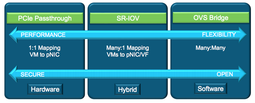
NFVIS supports numerous networking drivers for your VMs from OVS Bridge (E1000 & VIRTIO) options to SR-IOV, PCI and MACVTAP passthrough interfaces. The Meraki vMX allows E1000, VIRTIO and SR-IOV options but only SR-IOV is supported for maximum performance and scale.
The performance numbers for vMX-S (200Mbps), vMX-M (500Mbps) and vMX-L (1Gbps) are based off of the SR-IOV networking. E1000 and VIRTIO will likely result in lower performance (especially at scale as more and more vMXs are deployed).
OVS Bridge (E1000 and VIRTIO)
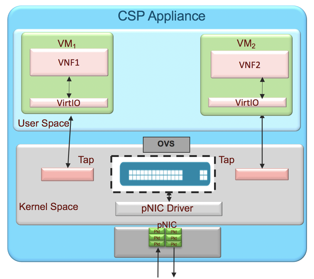
The E1000 network driver is the oldest of the three and subsequently the lowest performance. It is generally not advisable to use this NIC type. VIRTIO leverages DPDK (if enabled above) for accelerated networking and generally performs much better than E1000 but less than that of SR-IOV. The benefits of using E1000 or VIRTIO (at the cost of lower performance) is that they operate on an OVS (open vSwitch) bridge so you can create an LACP port channel of your physical NICs (PNIC) and create the E1000 or VIRTIO VNICs (VNIC) on top of that channel. This means that if any given cable or interface on that bond becomes unavailable, the VM will continue to operate over other links in the port channel automatically. With SR-IOV there is no link redundancy as each VM is bound to a specific port.
Single Root I/O Virtualization (SR-IOV)

Conversely to the above, SR-IOV networking gives higher performance but SR-IOV interfaces cannot be aggregated in to a port channel meaning that a vMX using SR-IOV is always tied to one physical interface and if that interface/cable goes down, the vMX will need to be reconfigured to use a different physical interface. NFVIS has a very robust API suite though making this a process that can be fully automated.
Use-Cases
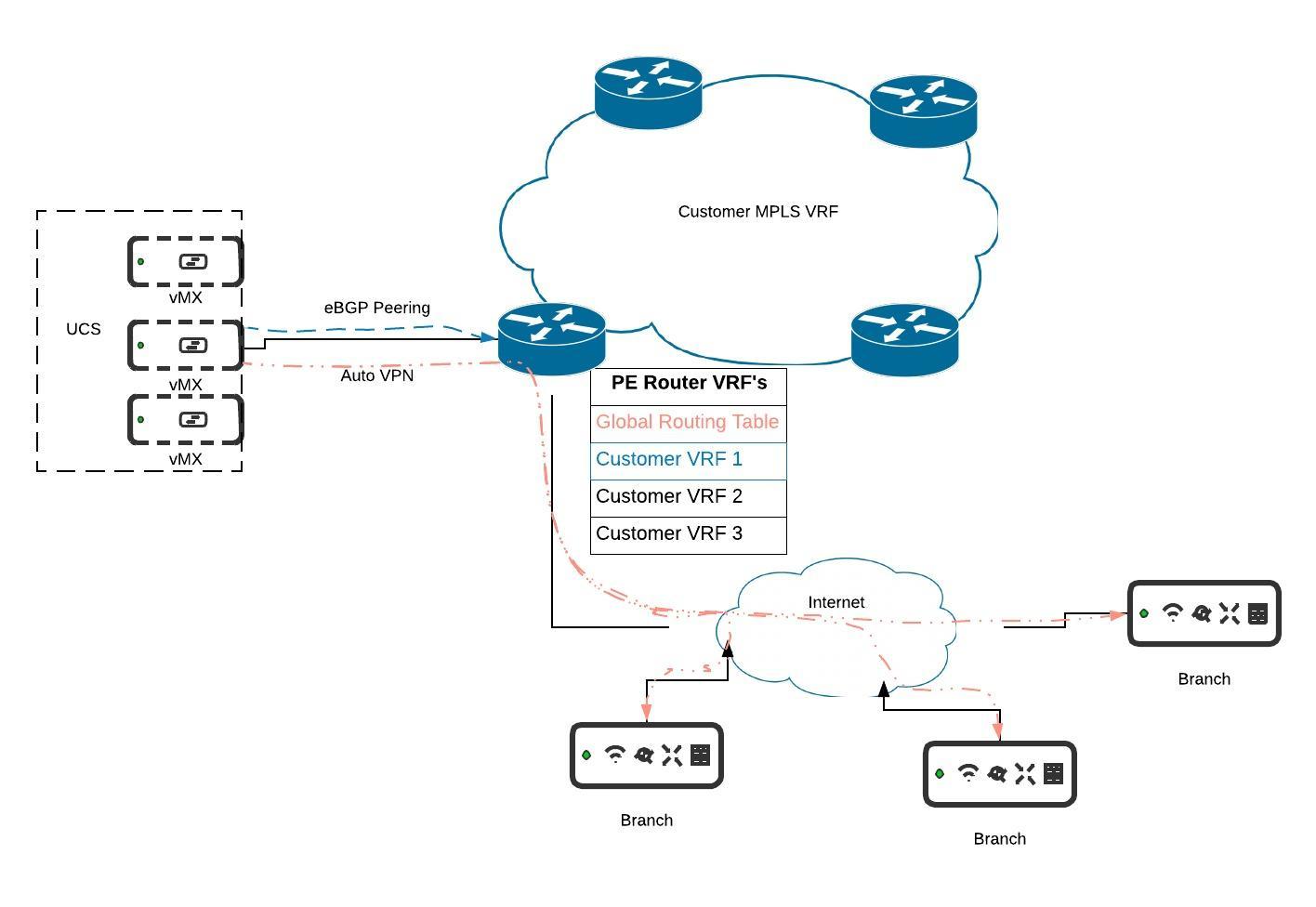
Multi-Tenancy
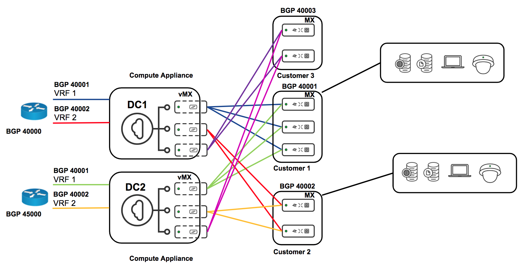
MPLS and BGP Integration with VRF's
For more details on this deployment setup please refer to the documentation here.
.jpeg?revision=1&size=bestfit&width=920&height=634)
Micro Segmentation with Source Based Routing
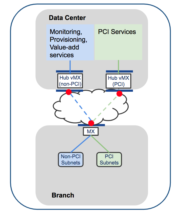
In MX15.4+ the ability to do source-based routing was introduced. This allows you to define a per-VLAN default route to either a local next hop on the LAN or to a VPN hub. We will focus on the VPN use-case (see diagram above).
At the branch you might have multiple VLANs which you want to keep truly segmented over the VPN and even at the DC. With a vMX-based solution you can spin up a vMX for each VLAN. At the branch you can direct VLAN 1 to hub 1, VLAN 2 to hub 2, etc. This will create a full-tunnel VPN for that VLAN to the specified hub. One such use-case for this kind of micro-segmentation could be for PCI compliance (although PCI compliance does not require this granular level of segmentation).