
Meraki Auto VPN - Configuration and Troubleshooting
Click 日本語 for Japanese
Overview
Auto VPN is a proprietary technology developed by Meraki that allows you to quickly and easily build VPN tunnels between Meraki WAN Appliances at your separate network branches with just a few clicks. Auto VPN performs the work normally required for manual VPN configurations with a simple cloud based process. This article outlines how the Auto VPN mechanisms work and how Meraki manages the cloud processes for Auto VPN.
Definitions
- VPN Registry: This is the main server mechanism that allows Auto VPN to happen. It is a cloud service that is used to keep track of the contact information for all the WAN Appliance participating in Auto VPN for an organization.
WAN Appliances in warm spare with Virtual IP address (VIP) will use VIP to communicate with the VPN registry.
- Hub: Hubs are devices in a VPN topology that service connectivity from a remote peer site (such as a spoke) to the hub and the hub to the remote peer site. Hubs also act as a gateway for remote peer sites to communicate with each other via the hub.
- Spoke: Remote sites that connect to a central hub and communicate with each other only through the hub.
- Peer: This refers to another WAN Appliance within the same organization that a local WAN Appliance will form or has formed a VPN tunnel to.
- Contact: This is the public IP and the UDP port that the WAN Appliance will communicate on for Auto VPN.
How Auto VPN Works
- MX1 and MX2 are part of the same organization. MX1 and MX2 are configured to participate in Auto VPN. Both MX1 and MX2 send a Register Request message to their VPN registry in order to share their own contact information, and to get the contact information of the peer WAN Appliance(s) that it should form a VPN tunnel with. The Register Request message contains the IP address and the UDP port that the WAN Appliance communicates on, and the WAN Appliance requests the contact information of its peer WAN Appliance(s).
- VPN registries send the Register Response messages to the WAN Appliances with the contact information of the peers the WAN Appliances should establish a tunnel with.
- Once the information is shared with the WAN Appliance about its peers, a VPN tunnel is formed WAN Appliance to WAN Appliance. The Meraki cloud already knows the subnet information for each WAN Appliance, and now the IP addresses to use for tunnel creation. The cloud pushes a key to the WAN Appliances in their configuration which is used to establish an AES encrypted IPsec-like tunnel. Local subnets specified by dashboard admins are exported/shared across VPN. During this process, VPN routes are pushed from the dashboard to the WAN Appliances. Finally, the dashboard will dynamically push VPN peer information (e.g., exported subnets, tunnel IP information) to each WAN Appliance. Every WAN Appliance stores this information in a separate routing table.
Any devices sitting upstream of a WAN Appliance will need the following destinations whitelisted so the WAN Appliance can communicate with the Auto VPN registries:
- Port
- UDP 9350-9381
- IP range for non-China cloud (meraki.com):
- 209.206.48.0/20
- 158.115.128.0/19
- 216.157.128.0/20
- IP range for China cloud (meraki.cn):
- 43.192.139.128/25
- 43.196.13.128/25
Ports used for IPsec tunneling:
- Source UDP port range 32768-61000
- Destination UDP port range 32768-61000
The VPN connection can be monitored under Security & SD-WAN > Monitor > VPN status page. The status of each WAN Appliance is displayed, along with their exported subnets, latency, connectivity and routing decisions that are being made over the Auto VPN domain in near real-time.
Auto VPN vs Non-Meraki Site-to-Site VPN
- Auto VPN is a VPN connection between/among the WAN Appliances in different networks of the same Meraki dashboard organization.
- Non-Meraki site-to-site VPN is used when you form a VPN tunnel with a third-party/non-Meraki device or when you establish a VPN connection with a Meraki WAN Appliance in a different dashboard organization.
- Like Non-Meraki Site-to-Site VPN, Auto VPN has encryption, authentication and a key. The traffic is encrypted using an AES cipher. However, all of this is transparent to users and does not need to be (and cannot be) modified.
Auto VPN: A Component of Meraki SD-WAN
| SD-WAN Characteristics | Meraki SD-WAN Component |
|---|---|
| Support for VPNs | Meraki Auto VPN |
| Multiple connection types (MPLS, Internet, LTE, etc.) | WAN Appliance uplink options allow for multiple connection type. |
| Dynamic path selection (allows for load sharing across WAN connection) | WAN Appliances can perform uplink load balancing across WAN connections |
| Simple WAN Configurations Interface (Must support zero-touch provisioning at a branch, should be easy to set up) | Meraki dashboard & API configuration interfaces |
Auto VPN, as a component of SD-WAN, transitions the manual steps for setting the VPN tunnel into a simple automated process. It takes only a few clicks and makes it easy to deploy and manage an SD-WAN environment. It gives resilience, security and application optimization. It has automatic VPN route generation using the IKE/IPSec-like tunnels and all this is done in the Meraki cloud.
If you have two uplinks on your WAN Appliance, Auto VPN as a component of SD-WAN allows you to decide the flow preferences within the VPN tunnel under Security & SD-WAN > Configure > SD-WAN & traffic shaping page > Uplink selection > Multi-Uplink Auto VPN. Multi-Uplink Auto VPN allows you to create a VPN tunnel with flow preferences over both the uplinks.
If Multi-Uplink Auto VPN is disabled, the tunnel will be formed over the primary WAN link and will failover to the secondary if the primary fails.
Auto VPN Configuration
To enable site-to-site VPN between WAN appliances, simply login to the Meraki dashboard and navigate to the Security & SD-WAN > Configure > Site-to-site VPN page, and select Hub or Spoke and save the page. That's all that is required to enable VPN connectivity. Auto VPN takes care of all connection settings and brokers the connections immediately.
Note that Auto VPN is a simple opt-in process. You can think of the WAN Appliances dashboard organization an existing VPN hub and spoke mesh topology environment, and every WAN Appliance that has Auto VPN turned on is simply choosing to participate in that mesh. By default, all hubs contact all other hubs, and all spokes contact specified hubs. Additional configuration options can be found below.
Auto VPN Configuration Details
Enable Auto VPN by defining how the WAN Appliance will communicate with the rest of the Auto VPN domain
If the WAN Appliance is configured as a Hub, it will build VPN tunnels to all other Hub WAN Appliances in the Auto VPN domain (in the same dashboard organization). It will also build VPN tunnels to all Spoke WAN Appliances in the Auto VPN domain that have this WAN Appliance configured as a hub. If all WAN Appliances in the Auto VPN domain are configured as Hub then the Auto VPN has a full mesh topology.

If the WAN Appliance is configured as a Spoke, it will build tunnels to only the WAN Appliances that are configured as its Hubs. If the majority of WAN Appliances in the Auto VPN domain are configured as Spoke with only a few key locations (such as data centers or headquarters) configured as hubs, then the Auto VPN environment has a hub-and-spoke topology.

Full Tunnel or Split Tunnel
By default all WAN Appliances in the Auto VPN domain (dashboard organization) will only send traffic to an Auto VPN peer if the traffic is destined for a subnet contained within the Auto VPN domain. This is often referred to as 'split-tunnelling,' meaning that VPN-subnet-bound traffic is sent over VPN, and other traffic is routed normally via the primary WAN Appliance WAN uplink. If an organization wants to route all traffic (including traffic not contained within the Auto VPN domain) through a specific hub site, this is referred to as 'full-tunneling.'
Note that full-tunneling only affects client data and all Meraki management traffic will egress directly via the primary WAN regardless.
To configure full-tunneling in a full mesh topology simply define an Exit hub from the WAN Appliances in the Auto VPN domain.

To configure full-tunneling in a hub-and-spoke topology, simply associate a ‘Default route’ with one or more hub WAN Appliances:

Choose which subnets (local networks) to export over VPN
Earmark which locally defined or available subnets are to be exported to the Auto VPN domain. Select Enabled under VPN Mode to define available subnets over the VPN.

Then save the changes so the WAN Appliance fetches the configurations from the cloud.
Troubleshooting Auto VPN
Learn more with these free online training courses on the Meraki Learning Hub:
Configurations that Use Automatic NAT Traversal
- Site-to-site VPN: When MX Series WAN appliances are configured to create a VPN between two or more sites within the same Organization.
- Teleworker VPN: When MR Series access points have an SSID configured to tunnel all traffic back to a central concentrator. This concentrator can be either an MX Series WAN appliance in passthrough/concentrator mode, or a VM (Virtual Machine) concentrator.
Troubleshooting VPN Registration
When using VPN functionality to securely tunnel traffic between Cisco Meraki devices, such as the WAN Appliance Site-to-site VPN, or Access Point Teleworker VPN, the devices must first register with the Dashboard VPN registry. This allows their connections between each other to be dynamic, and automatically establish without manual configuration. However, sometimes issues can occur with this process, which will be discussed in this article.
In order to ensure connectivity, each Meraki node sends a keepalive message to the VPN Registry every 10 seconds. If more than 6 keepalives are not received by the registry, that node is marked as disconnected. For information on how connectivity to the VPN Registry works, please read the article on Automatic NAT Traversal.
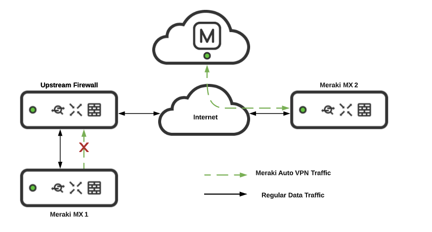
Both Meraki peers must be in communication with the VPN registry in order to get the correct information to form a valid VPN tunnel. If one Meraki device, such as an MX WAN appliance, is able to reach the VPN registry, but the intended peer WAN Appliance is not, the tunnel will not form. A common occurrence of this is when an upstream firewall blocks VPN registry communication on UDP port 9350-9381. This issue is explained in the section VPN Registry Disconnected.
If the appliance/concentrator is successfully connected to the VPN registry, but is disconnected from another VPN peer, refer to the article on troubleshooting VPN connections between peers.
VPN Registry Disconnected
When the "VPN Registry: Disconnected" message appears on the Security & SD-WAN > Monitor > VPN status page for WAN Appliance networks, it indicates that the appliance has been unable to establish connectivity with the VPN registry. This means that a firewall or other upstream device is either preventing traffic from reaching the VPN registry, or from returning to the appliance.

Expected behavior. If the WAN Appliance loses connectivity to the VPN registry, peer information gets purged over time but not immediately. Connectivity to the registry matters when a node changes its contact information after losing connectivity to the VPN registry.
Both the hub and spoke will still be able to form the tunnel if the contact information remains the same, and they lost registry connectivity. Peer information will purge after a few hours causing the tunnel to be marked down.
Examples
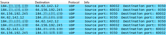
In the example packet capture below, a WAN appliance is attempting to reach the VPN registry on UDP port 9350, but is receiving no response because an upstream firewall is preventing the outbound traffic:

In this example, the appropriate firewall rules have been added to allow the traffic to the VPN registry, and responses can be seen:
Solution
If this occurs, make sure that any upstream firewalls are configured to allow traffic to the IP addresses and ports listed on the Help > Firewall info page. Particularly for the VPN registry. It should also allow return traffic from established connections (this is allowed by default for stateful firewalls):

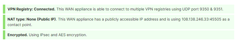
NAT Type: Unfriendly
UDP hole-punching, the mechanism used to establish the VPN connections between Cisco Meraki devices, relies on a consistent IP address and port for both devices involved. Two VPN registry servers are used for redundancy, and both expect to see the device as available on the same public IP address and port.
However, some NAT devices (such as a firewall) will rewrite the source ports differently for each VPN registry server. Other NAT devices or load balancers will attempt to spread the connections to each VPN registry server across two different public IP addresses. Both of these cases will result in the VPN connection failing, and marking the NAT as unfriendly:

Examples
In this example the upstream firewall rewrites the source port for each outbound connection differently. Notice that the first connection is changed to port 56125 while the second is instead 56126. When the registry servers see different source ports, the NAT unfriendly error will appear:

In this example, the upstream firewall is load balancing connections over two WAN connections, and then performing NAT using two different public IP addresses. Notice that the first connection is sent from the 198.51.100.23 address, while the second is sent from 198.51.100.17 instead. When the registry servers see different source IP addresses, the NAT unfriendly error will appear:

Solutions
If using a load balancer, or NAT across multiple public IP addresses, map traffic from the internal address of the appliance to a single public IP address. This will keep the public IP address seen by the VPN registry consistent.
-OR-
Select an arbitrary port that will be used for all VPN traffic to this WAN Appliance (e.g. UDP port 51625). Manually create a port mapping on the upstream firewall that will forward all traffic received on a specific public IP and port to the internal address of the appliance on the selected port. In Dashboard on the Security & SD-WAN > Configure > Site-to-site VPN page use the Manual: Port forwarding option for NAT traversal, and provide the public IP address and port that was configured. All peers will then connect using this IP address and port combination.
Troubleshooting Automatic NAT Traversal
Cisco Meraki VPN peers can use Automatic NAT Traversal to establish a secure IPsec tunnel through a firewall or NAT. When ACLs on an upstream firewall block source ports or more likely the case destination UDP ports in the range 32768-61000 on outbound traffic, a peer will not be able to punch a hole in the firewall and establish a tunnel with other remote peers.
Note: Cisco Meraki VPN peers must be able to use high number UDP ports to communicate with each other. Security systems such as firewalls that disallow this traffic may prevent successful traffic flow over the VPN. Please follow the diagnostic and troubleshooting steps below to resolve such issues.
In the example below, the firewall blocks peer1 from sending outbound UDP packets in the necessary destination port range. This prevents a hole punch. Now when peer2 tries to send inbound packets, its packets are dropped on the outside interface of the firewall because they do not match an existing outbound session. In this instance the tunnel will not be established between peer1 and peer2.

Failed connectivity tests or a VPN status of 'disconnected' indicates a tunnel failure between peers in Dashboard.
In a site-to-site VPN if two peers are unable to establish a VPN connection they will show as disconnected on each other's VPN status page. In this case, a packet capture should be taken on the primary Internet interface of both peers to analyze which firewall is blocking IPsec communication.
Analyzing a Packet Capture for IPsec Connectivity
Packet captures can be taken from Dashboard and downloaded as a .pcap file for analysis and filtering using Wireshark packet analyzer. They are invaluable for troubleshooting connections between hosts and isolating connectivity issues.
In the example below there is an Access Point to VPN concentrator tunnel that will not establish. We take packet captures from different points in the path to help determine which firewall is blocking the peer-to-peer communication.
The first capture, shown below, was taken from the wired interface of the Access Point 10.0.8.99. We can see the Access Point attempting to punch a hole in its local upstream firewall by sending packets to 208.72.143.11, which is the outside IP address of the NAT that the VPN concentrator sits behind. Notice the the Access Point is sending traffic to the concentrator but there is no return traffic in the capture from the WAN appliance behind the NAT.
Access Point 10.0.8.99:45540 -> WAN Appliance 208.72.143.11:53654

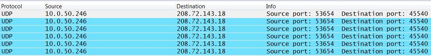
A second capture, shown below, was taken from the inside interface of the WAN Appliance upstream from the VPN concentrator. The VPN concentrator uses IP address 10.0.50.246 on the LAN. We can see the VPN concentrator sending packets to 208.72.143.18 which is the outside IP address of the NAT that the Access Point sits behind in an attempt to punch a hole in its local upstream firewall. Notice the VPN concentrator is sending traffic to the Access Point but no return traffic is present from the Access Point behind the NAT.
WAN Appliance 10.0.50.246:53654 -> Access Point 208.72.143.18:45540
A third capture was then taken, this time from the outside interface of the WAN Appliance upstream from the VPN concentrator. We can the see the VPN concentrator's traffic has been translated to 208.72.143.11, which is the firewall's outside IP address, and that it is being forwarded onto the Internet. This indicates the firewall is not blocking outbound IPsec traffic in the VPN concentrator site. However, we do not see any traffic originating from 208.72.143.18, the IP address of the NAT device the Access Point sits behind. From this we can conclude that the firewall upstream from the Access Point is blocking outbound IPsec traffic within the UDP port range 32768-61000.
WAN Appliance 208.72.143.18:53654 -> Access Point 208.72.143.18:45540
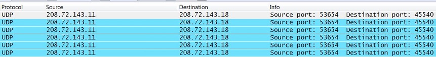
To confirm, we take a final capture from the outside interface of the WAN Appliance upstream from the Access Point, shown below. This capture shows packets originating from the VPN concentrator at 208.72.143.11 and arriving at the Access Point firewall's outside interface at 208.72.143.18. We still do not see any traffic originating from the Access Point being sent from the outside interface. This indicates the WAN Appliance is in fact blocking outbound IPsec traffic on the inside interface, specifically destination UDP port range 32768-61000.
WAN Appliance 208.72.143.18:53654 -> Access Point 208.72.143.18:45540

Once we reconfigure the firewall upstream from the Access Point to allow outbound destination port range 32768-61000, peers are able to form a tunnel. Although the first 4 captures are filtered by UDP ports 53654 and 45540, once the firewall is opened two-way traffic can occur on any dynamically chosen ports as shown below on a packet capture taken from the wired interface of the Access Point. Now the Access Point is registered with and using with port 41091 for VPN communication.
Access Point 10.0.8.99:41091 -> WAN Appliance 208.72.143.11:53654
Access Point 10.0.8.99:41091 <- WAN Appliance 208.72.143.11:53654

Below are two examples of ACLs that could be used to allow peer-to-peer communication between Cisco Meraki VPN peers. For the second option, X.X.X.X/32 represents the IP address of the Cisco Meraki device.
allow inside to outside, protocol: udp, source ip: any, src port: any, dst ip: any, dst port: 32768-61000
allow outside to inside established (may not be necessary with stateful firewalls)
-OR-
allow inside to outside, protocol: udp, source ip: X.X.X.X/32, src port: 32768-61000, dst ip: any, dst port: 32768-61000
allow outside to inside established (may not be necessary with stateful firewalls)
Access Point to WAN Appliance Concentrator Testing
With an Access Point to WAN Appliance concentrator connection type, use the Test connectivity button on the Wireless network. Running the test will report which Access Points "failed to connect to the concentrator." Please note if the issue is on the concentrator side, it is likely that all Access Points will fail the test. A packet capture should be taken on the wired interface of each Access Point that failed to connect to the concentrator. Another capture should be taken from the primary Internet interface of the WAN Appliance. These captures can be analyzed to determine which site's firewall is blocking outbound IPsec communication.