How to Set Up an Alternate Management Interface on MS Devices
Click 日本語 for Japanese
Overview
This article explains how to configure the Alternate Management Interface (AMI) on Meraki MS series switches.
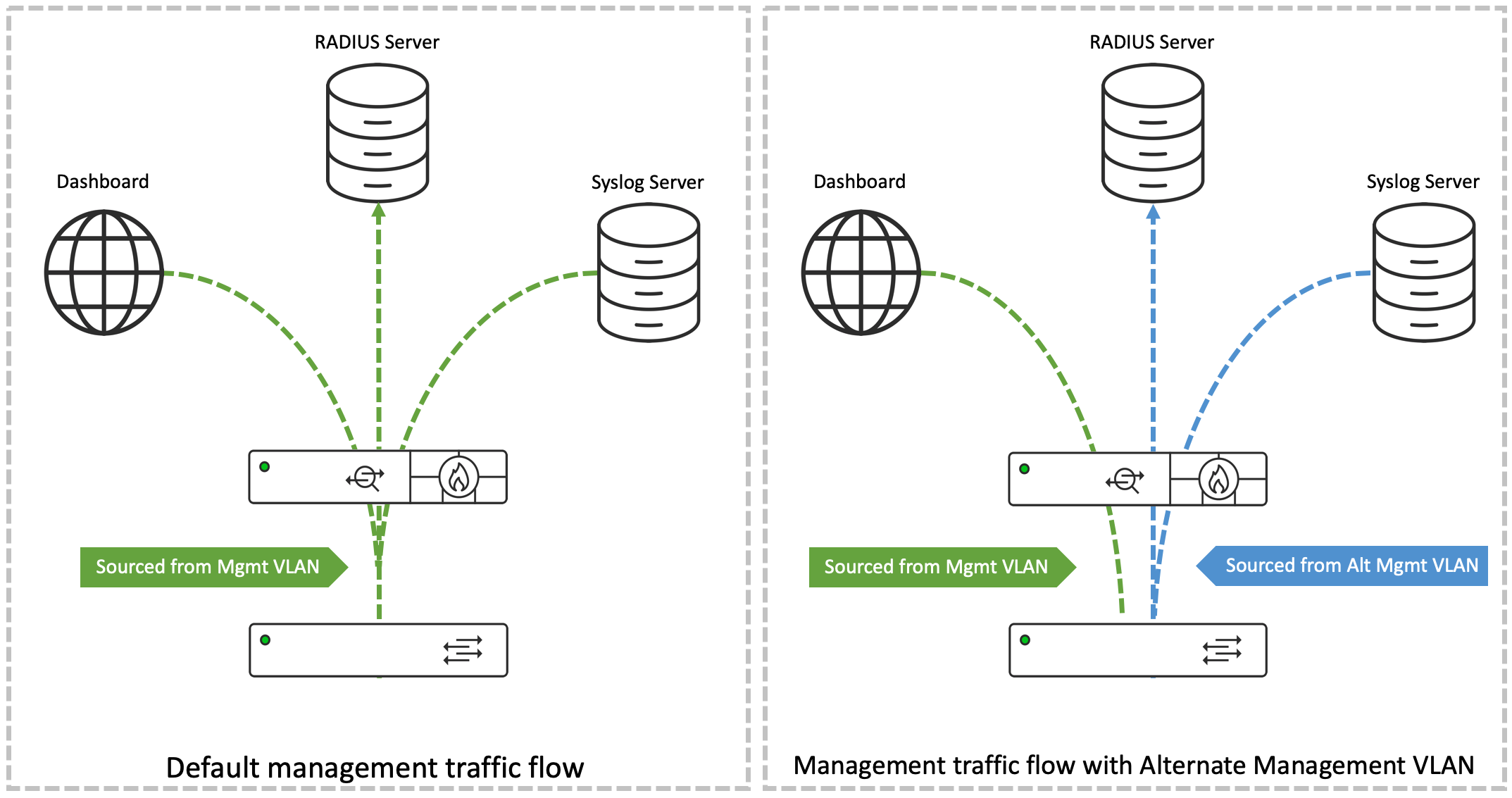
In traditional Meraki network deployments, management traffic — such as Syslog messages, responses to SNMP polling, and communication with RADIUS servers — is sourced from the LAN IP, which is the address of the device's default management VLAN. The MS device also uses this VLAN to communicate with the Meraki Dashboard, so it has connectivity to the Internet.
Some deployments enforce security policies that require isolating management traffic from public networks. The Alternate Management Interface feature supports this by enabling an MS series switch to source its management traffic from an IP address other than that of the default management VLAN.
Sourcing management traffic from the Alternate Management VLAN's IP avoids overlap and separates return traffic from servers out of the public network.
Flow of Traffic with Alternate Management Interface
Traffic for the services selected under the AMI configuration is routed in accordance with the information in the routing table of the switch. AMI VLAN's IP is used as the source IP address of the data packets being sent. Souring this traffic from the IP address of the Alternate Management VLAN allows us to avoid any overlap and ensure that the return traffic from servers can be separated from the public network.
Prerequisites
Before you configure AMI, confirm the following requirements, guidelines, and limitations.
- Hardware and software requirements:
AMI is supported on the following MS switch platforms and firmware versions.
| MS Switch Family | MS Switch Model | MS Firmware Support (first supported on) |
| MS100 Series | MS150 | MS17 |
| MS200 Series | MS210 | MS14.5 |
| MS225 | MS14.5 | |
| MS250 | MS14.5 | |
| MS300 Series | MS350 | MS14.5 |
| MS355 | MS14.5 | |
| MS390 | MS15 | |
| MS400 Series | MS410 | MS14.5 |
| MS425 | MS14.5 | |
| MS450 | MS14.5 |
- Additional guidelines
- AMI is enabled at a per-network level. All switches within the Dashboard network use the same VLAN for the AMI. You can configure the AMI IP address per switch.
- The AMI VLAN should not match the Management VLAN configured on any of the switches (the LAN IP VLAN on the switch details page) or for the network (via Switching > Switch settings > VLAN configuration).
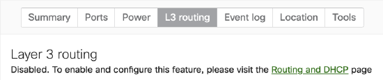
- Enable Layer 3 routing on a switch to activate its AMI. Refer to the section "Step 3 – Configure switches with routes toward management servers" for details.
Step-by-step instructions
Configure AMI using Meraki dashboard
Configuring the MS switches in a Meraki Dashboard network to use AMI involves the key steps:
Step 1 – Enable AMI for network and associate management services
-
Go to Network-wide > General.
-
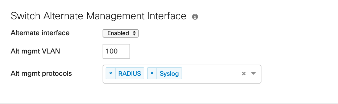
Locate the configuration options. Find them under the Alternate Management Interface section if the network type is Switch, or under Switch Alternate Management Interface if the network type is Combined.

-
Specify the alternate management VLAN.
-
Choose a combination of services from RADIUS, SNMP, and Syslog to which the Alternate Management Interface configuration applies.
Step 2 – Configure the AMI IP addresses on switches
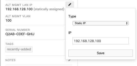
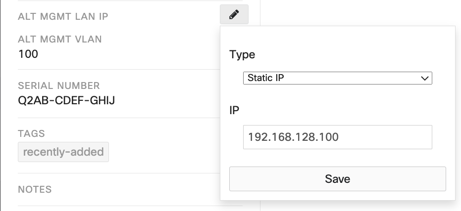
Once you enable the Alternate Management Interface, the AMI VLAN number populates as the ALT MGMT VLAN on all switches in the network that support AMI.
-
Refer to the Switch details page for each switch.
-
Assign the Alternate Management Interface IP statically per switch.
The subnet of the AMI (the subnet mask for the AMI IP address) derives from the Layer-3 interface for the AMI VLAN, if one is configured on the switch. Without a Layer-3 interface for the AMI VLAN, each switch treats its AMI as a /32 network address.
Step 3 – Configure switches with routes toward management servers
The switch relies on its routing table entries to determine the IP address of the next-hop device for exporting traffic for protocols mapped to AMI.
-
Configure the required routes statically or through a dynamic routing protocol.
-
Refer to Switch > Routing & DHCP on the Dashboard to set the routes.
For details on routing configurations and their dependencies in MS switches, refer to the MS Layer 3 Switching and Routing document.
Configure AMI using API
GET Alternate Management Interface Configuration
The GET /networks/{networkId}/switch/alternateManagementInterface request is used to obtain the current Alternate Management Interface configuration of a Dashboard Network and on the switches in it. Some examples of response to these requests are as follows.
For details of the API request, check the API documentation.
Example response from Network Templates
Successful HTTP response code: 200

{
  "enabled": true,
  "vlanId": 100,
  "protocol": [
    "snmp",
    "radius",
    "syslog"
  ]
}
Example response from Networks when AMI is enabled
Successful HTTP response code: 200

{
  "enabled": true,
  "vlanId": 100,
  "protocols": ["radius","snmp","syslog"],
  "switches": [
    {
      "serial": "Q2AB-CDEF-GHIJ",
      "alternateManagementIp": "192.168.128.100"
    },
    {
      "serial": "Q2AB-CDEF-KLMN",
      "alternateManagementIp": "192.168.128.200"
    },
    .....
  ]
}
Example response from Networks when AMI is disabled
Successful HTTP response code: 200

{
  "enabled": false,
}
PUT Alternate Management Interface Configuration
Use the PUT /networks/{networkId}/switch/alternateManagementInterface request to configure AMI on a network. The following table provides some example configurations and their corresponding responses.
For details of the API request, check the API documentation.
| Request | Response |
| Configure Network-wide Switch AMI settings | |
PUT /networks/L_12345/switch/alternateManagementInterface

{
  "enabled": true,
  "vlanId": 100,
  "protocols": ["syslog"]
}
|
Successful HTTP response code: 200

{
  "enabled": true,
  "vlanId": 100,
  "protocols": ["syslog"],
  "switches": []
|
| Configure AMI IP addresses on switches | |
PUT /networks/L_12345/switch/alternateManagementInterface

{
  "switches": [
    {
      "serial": "Q2AB-CDEF-GHIJ",
      "alternateManagementIp": "192.168.128.100"
    },
    {
      "serial": "Q2AB-CDEF-KLMN",
      "alternateManagementIp": "192.168.128.200"
    }
  ]
}
|
Successful HTTP response code: 200

{
  "enabled": true,
  "vlanId": 100,
  "protocols": ["syslog"],
  "switches": [
    {
      "serial": "Q2AB-CDEF-GHIJ",
      "alternateManagementIp": "192.168.128.100",
    },
    {
      "serial": "Q2AB-CDEF-KLMN",
      "alternateManagementIp": "192.168.128.200"
    }
  ]
}
|
| Configure Network-wide settings and AMI IP on switch | |
PUT /networks/L_12345/switch/alternateManagementInterface

{
  "enabled": true,
  "vlanId": 100,
  "protocols": ["syslog"],
  "switches": [
    {
      "serial": "Q2AB-CDEF-GHIJ",
      "alternateManagementIp": "192.168.128.100"
    }
  ]
}
|
Successful HTTP response code: 200

{
  "enabled": true,
  "vlanId": 100,
  "protocols": ["syslog"],
  "switches": [
    {
      "serial": "Q2AB-CDEF-GHIJ",
      "alternateManagementIp": "192.168.128.100"
    }
  ]
}
|
| Disable Switch AMI on the network | |
PUT /networks/L_12345/switch/alternateManagementInterface

{
  "enabled": false
}
|
Successful HTTP response code: 200

{
  "enabled": false
}
|
Verification
Verify the AMI configuration on both the dashboard and the switch.
Troubleshooting
-
AMI IP not displayed in the UI: Without Layer-3 routing on the switch, the switch will not accept the AMI IP address. In this scenario, you can configure the AMI IP, but it will not show up in the UI. The ALT MGMT VLAN section correctly reflects the AMI VLAN, but the ALT MGMT LAN IP does not display the configured IP address.
-
Check Layer-3 routing state: Verify the state of Layer-3 routing on the switch from the L3 routing tab on the Switch details page.