
RRM: Radio Resource Management for Wi-Fi Channel and Power Management
Click 日本語 for Japanese
Learn more with these free online training courses on the Cisco Learning Hub:
RRM Overview
RRM is a set of RF features on Cisco Wireless access points that is built on the following Algorithms: Transmit Power Control (TPC), Dynamic Channel Assignment (DCA), Dynamic Bandwidth Selection (DBS) in order to understand what’s in the RF Spectrum and manage the networks resources dynamically as conditions change. Based on the environmental factors it detects, RRM can automatically tune settings such as channel assignments, per-radio transmit power, and band steering to optimize coverage and performance of the network.
RRM relies on data collected over the air by every AP on the network, giving it a holistic view of the entire network. Each AP and its including interference from other Wi-Fi networks and non Wi-Fi devices is mapped and fed to the RRM algorithms which will work to solve for optimal coverage and interference avoidance to maintain a high performing network experience for the users. RRM is aware of real time Channel status, RF utilizations, interference source for all devices sharing the spectrum for neighborhood APs from own network as well as external networks from the RF Neighborhood(s). RF Neighborhood is dynamically formed by group of APs within same proximity.
*For all Artificial Intelligence powered by AI-Enhanced RRM features in RRM please refer to the AI-RRM document.
Note: on Event Log Changes: Transition from AutoRF to Cisco RRM
As part of our ongoing commitment to continuous improvement and RF excellence, Cisco is transitioning from AutoRF to a unified Cisco Radio Resource Management (RRM) framework. As a result, customers may notice changes in the event log, including:
- Event Type Name Changes: Event logs that previously referenced "AutoRF" are now being recorded as "RRM" events.
- Consistency Across Deployments: This update is being gradually rolled out across all environments to ensure a consistent RF management experience.
Why am I seeing different event names or missing AutoRF events?
These changes are a result of the commitment to continuous improvement and RF excellence. The underlying functionality remains focused on optimizing your wireless environment, but the event naming and structure in logs have been updated to align with Cisco RRM standards.
If you have questions or need further assistance regarding these changes, please reach out to Support.
The high level view, RRM is a framework of services used to gather relevant over the air information and store it for analysis. Each AP listens within its environment and collect a variety of statistics about who and what is using the air. Each AP will gather information regarding Neighbors (Neighbor Discovery Protocol) channel conditions – Load, Interference (rogues, non-Wi-Fi and Noise. This information is sent to the dashboard and used to determine the structure of the RF Group and identifying the individual RF Neighborhoods. An RF Neighborhood is a group of AP's that can hear one another, and as such must have channel and power solutions calculated together.
In this scenario, the Meraki Dashboard at the network level becomes the RF Group Leader, which is the designated process that will host and run the RRM Algorithm's on information that it collects from all APs belonging to the network. It does this by first identifying groups of APs that are physically close enough to one another and organizing these into RF Neighborhoods. The RF Group Leader is also the repository for the current RRM configurations (for channel and power) that will be used to configure the Algorithms for the RF Group.
DCA - Dynamic Channel Assignment
DCA dynamically adjusts the channels being used to avoid RF interference (both 802.11 and non-802.11) and develops an optimal channel plan for the wireless network. DCA’s default assumptions are a good fit for most wireless networks, and should provide a balanced baseline channel configuration. The configuration can then be adjusted manually if needed.
DCA assigns the AP its operating channel. As conditions change, DCA re-evaluates the current assignment, and if necessary will assign a new channel for the access point to operate on. DCA uses a complex SNR calculation made on the channel compiled from its observations of both on and off network Wi-Fi as well as non-Wi-Fi sources. The RF dynamics are perpetually changing during an online day. It is important to note that changing channels, is disruptive to client traffic. For this reason, it’s important to know that just because we see a channel in the moment that appears better, is it better enough to warrant a change. To determine this , DCA uses a system of Hysterisis’s based on Customer selectable sensitivity preferences. High Sensitivity would be more likely to take a new channel with less hysteresis, indicating the preference for higher performance at the cost of some stability. To low, where we would not make a change unless it is significantly better favoring more stability and less network convergence events.
DCA adds a second step to this evaluation. In order for a channel change to be processed, it must be able to make this change, without significantly impacting all of the neighbors in its local RF neighborhood.
Configuration
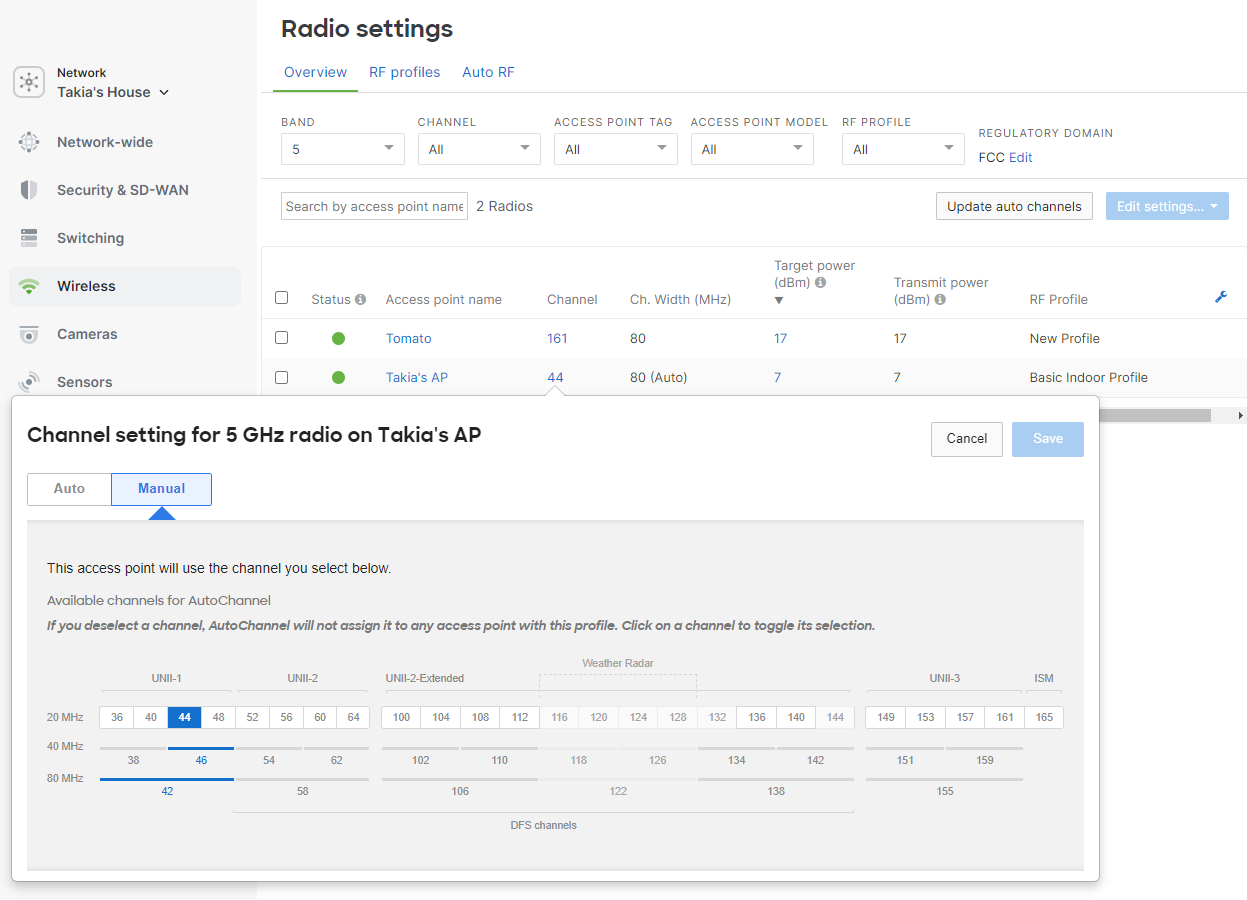
DCA is enabled by default on all Cisco Wireless access points. To ensure DCA is enabled on an AP, navigate to Wireless > Configure > Radio settings > Overview on the list of access points on the page, each lists the current channel assigned and the method “[Auto]” will be displayed if DCA is making the assignment.
2.4 GHz Channel Selection
Cisco Wireless access points follow best practices and industry standards in the Auto Channel selection, so an AP's 2.4 GHz radio will only be set to channels 1, 6, and 11. Because they do not overlap in frequency, these three channels have the least amount of co-channel interference. Other channels are included in the list and may be selected manually to override the DCA algorithm, but this is not recommended.

5 GHz Channel Selection
Channel availability for 5 GHz varies based on AP model and regulatory domain. The access point will consider any channel that it is certified in the regulatory domain of operation. A list of channels can be viewed by opening the channel drop-down for the AP on the radio settings page. There is no preference for a particular band and all channels are weighed evenly.
Exclude Dynamic Frequency Selection (DFS)
Some use cases may require that Dynamic Frequency Selection (DFS) channels are excluded from the Auto Channel algorithm. DFS channels can be allowed or excluded on the radio settings page in the dashboard by navigating to Wireless > Radio Settings > RF Profiles > Select the RF Profile you need to configure and navigate to Change channels used by AutoChannel > Deselect DFS Channels.
Disabling the DFS channels is not a recommended approach because it severely limits the amount of spectrum (up to 255 MHz, up to 12x 20 MHz Channels) available to the network. This may be selected in your network because of legacy issues. Please consider AI Channel planning (documented below). AI-Channel planning will manage excessive DFS and Jamming issues on a per AP basis, automatically and preserve the spectrum /channels in areas where it is not seen as an impact.
DFS events will occur when an AP operating on a DFS channel overhears radar transmission. At that time, they are required to immediately switch over to another channel.
The event log will include DFS detected, channel, and radio information.
|
1 |
6 GHz Channel Selection
Channel availability for 6 GHz varies based on AP model and regulatory domain. The access point will consider any channel that it is certified in the APs regulatory domain of operation. A list of channels can be viewed by opening the channel drop-down for the AP on the radio settings page. In Wi-Fi 6E and newer standards, Preferred Scanning Channels (PSC) are a subset of channels within the 6 GHz band that are prioritized for scanning by devices to find access points, PSC are spaced every 80 MHz. In the 6 GHz band, the PSC include channels 5, 21, 37, 53, 69, 85, 101, 117, 133, 149, 165, 181, 197, 213, and 229. DCA will assign both PSC and non PSC channels based on channel width. A 20 MHz channel will be equally assigned both PSC/non PSC, a 40 MHz channel will show some PSC Bias. This is done mostly to maximize at least 50% PSC assignments and avoid P20/S20 alignments. An 80 MHz channel is mostly biased for PSC. Anything over 80 MHz will be biased for a PSC assignment.

AFC
Automated Frequency Coordination System is a cloud-based operator (Example: Federated Wireless, Open AFC) that has access to FCC and ISED (US and Canada’s) 6 GHz, incumbent database, which stores geolocation coordinates and power of these licensed wireless services operating in the 6 GHz spectrum. For 6 GHz radios wanting to operate in the SP (Standard Power) mode outdoors or indoors are required to receive their allowed channels and power from an AFC provider. AFC is required to avoid interference from the access point with licensed incumbent 6 GHz devices operating nearby. In order for AFC to operate the network will need a solid plan for enabling GNSS on the APs and a design for GNSS distribution must be in place for success. If you are planning such a deployment please see the Automatic Frequency Coordination Deployment Guide.
Radio Channel Width
The dashboard offers the ability to set a default channel width, which will be factored into the Auto Channel algorithm for 5 and 6 GHz. This can be left at auto width which will adjust the width of the 5 and 6 GHz radio based on the Auto Channel algorithms discussed below.
The optimal channel width assigned is a function of how dense your network is. While an 80 MHz channel may be attractive, many factors actually determine if it should be set to 80 Mhz. There is a finite limit to the number of 20 MHz channels each country allows to be used for Wi-Fi. An AP using a 40 MHz channel uses 2 channels (2x20 MHz = 40) and an 80 MHz channel uses 4 of them. Wi-Fi is self porganizing and forgiving, in that it can avoid interfering with itself. However, APs on the same channel will compete for the airtime and while the outcome may be fair, it does not mean performance will also be good. Co-Channel interference reduces throughpiut but even worse dramatically increases latency (network delays).
In the US, with 28 channels in 5 GHz and 59 available in 6 GHz, recommended defaults would be 40 MHz for 5 GHz and 80 MHz for 6 GHz. In European countries, this could be the same at 40 MHz for 5 GHz with caution (Europe has fewer channels than the US), and 6 GHz has much less spectrum with only 29 of the 59 channels in the US. The general recommendation there is to only use 40 MHz as well.
Setting a wider channel width than your network can sustain will result in co-channel interference increasing. This is when two APs are operating on the same channel, and they are close enough to hear one another. If both APs are very busy, they will each get roughly half of the channel bandwidth as they share it with each other. The time it takes a packet to transit or the latency also increases because of the reduced bandwidth.
Automatic Channel Width will allow individual APs to be assigned higher or lower channel widths based on demand, client type/capabilities, and co-channel interference levels.
5 GHz

6 GHz

Note: The TPC (Transmit Power Control) algorithm will never set the transmit power below 2 dBm for 2.4 GHz and 5 GHz radios.
Note: Cisco Wireless APs that do not support 80, 160, or 320 MHz-wide channels will default to their closest maximum for their channel width.
RF Metrics
Cisco Wireless APs are constantly collecting information from the RF environment; the dedicated scanning radio continually monitors on all channels for Air Marshal and RF. The table below outlines in detail the metrics that are collected by each AP and analyzed by the cloud controller for the real-time Auto Channel algorithm:
|
Metric |
Description |
|
Usage demand |
Some APs handle a greater load than other APs in the same network. APs within the dashboard network are monitored for their usage demand. Client count and traffic are calculated to weigh the "value" of one AP vs. another. This metric helps ensure the cleanest channels are used in the most demanding areas. |
|
Airtime availability |
Every access point measures contention and airtime availability for each channel and bandwidth combination. This metric maximizes available airtime for the BSS, which also minimizes contention and improves performance and roaming. Cisco Wireless APs registered within the dashboard and out-of-network APs are considered in this metric. APs within the dashboard network are weighed higher to optimize roaming and airtime usage distribution. Rather than just counting and considering the number of overlapping networks, this metric ensures that the AP will coexist on a channel and have ample airtime availability. |
|
Channel utilization |
Channel utilization includes both 802.11 and non-802.11 sources. External sources of interference like microwaves and DAS systems are detected by this metric and can be seen on the RF spectrum page. |
*has a different BSSID and in most cases a unique virtual MAC is used that is based on the hard-coded radio MAC. BSSIDs are discovered by the Cisco Wireless access point by both passive scanning and active probing on each channel.
The dashboard collects information reported by the deployed APs such as channel utilization, noise, interference, and how well it hears the other AP neighbors. The dashboard may instruct an AP to change to a different channel for a number of reasons, such as when a new AP is added, or something in the environment changed and there was an increase in noise or a new source of interference. The APs in a network will use the information they have gathered from the environment and will calculate to see if there are any channels that have better performance. If an AP determines there are better channels, the AP will switch to it when the Dynamic Channel updates every 30 minutes.
Channel Changes
Channel adjustments are made by the dashboard using information reported by the deployed APs. The dashboard will instruct an AP to change to a different channel for a number of reasons, outlined below:
New AP added
The dashboard will automatically adjust the channel on a new AP to a channel that is best optimized for the location where the AP is installed. The dashboard will collect information from the newly added AP and will select the channel that best fits within the existing wireless network.
Adding a new AP will not cause neighboring APs to change channels immediately. Neighboring APs will adjust their channels based on the other reasons outlined below.
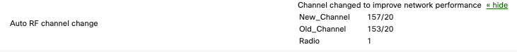
Logging
The event log will report this type of channel change as "Channel set for new AP," and the API will return reason value 1. This event will include the radio number, old channel, and new channel. Below is an example of one of these events:

Opportunistic Auto Channel
Cisco Wireless APs that do not have a dedicated scanning radio (or APs with a third radio disabled due to power restrictions) will use the opportunistic Auto Channel algorithm. This algorithm uses similar metrics to the real-time Dynamic Channel Assignment covered above. The data is collected every two hours via opportunistic scanning and will scan off-channel if clients are not connected. Because information is collected over a longer time period and there is limited real-time visibility to other channels, the frequency of channel change opportunities is reduced.
Channel Changes
Channel changes are more conservative/less frequent because the AP needs to make more assumptions on the channel quality when comparing it to the real-time algorithm. There are three main cases in which a channel will be changed with the opportunistic Auto Channel:
- New AP added
- Steady state
- Update Auto Channel button
Steady state channel changes will only occur at night or during periods of low network usage. Administrators are able to force a scan with the opportunistic Auto Channel algorithm by pressing the Update Auto Channel button on the radio settings page in the dashboard.
TPC - Transmit Power Control
Each AP samples the signal-to-noise ratio (SNR) of neighboring APs that reside in the same dashboard network. All radios on an AP can perform the sampling. The SNR readings are compiled into neighbor reports which are sent to the cloud for processing. The cloud aggregates neighbor reports from each AP. Using the aggregated data, the cloud can determine each AP's direct neighbors (neighbors that a client might directly roam to) and how much each AP should adjust radio transmit power so coverage cells are optimized. Once calculations are complete, the cloud instructs each AP to decrease (or in some instances increase) transmit power to reach an optimal power level. The TPC process is performed every 30 minutes for each AP in the dashboard network on both 2.4 GHz and 5 GHz radios.
Real-Time TPC Process
This example demonstrates the process, with a dashboard network containing four APs with overlapping coverage.
- Each AP will sample its RF Neighborhood identifying it’s neighbors (on and off network) and compile these readings into a neighbor report to be sent to the cloud.

- The cloud requests the neighbor report from each AP in the dashboard network.

- Once the cloud has the reports from each AP, it aggregates them and determines each AP's direct first hop neighbor(s) and how much (if any) each AP should adjust their transmit power to achieve an optimal coverage overlap. If necessary, the TPC algorithm will lower the transmit power of each AP within a range of 1 dB - 3 dB once per iteration or increase the transmit power as much as necessary immediately (this to protect for a lost cell). The target is to provide the optimal SNR for all of a given APs direct neighbors,
- Once transmit power levels have been calculated, the cloud iterates through each AP in the dashboard network, instructing them to decrease or increase their transmit power. If the target SNR is already met, no transmit power adjustment is sent.

- This process is repeated every 30 minutes on each AP in the dashboard network.
Opportunistic Auto TX
The Transmit Power Control (TPC) algorithm is available only to devices with a third radio (Ex. MR18, MR34, etc.). Other devices will use the opportunistic Auto TX algorithm. This algorithm uses a different metric set to determine the appropriate power level since the AP does not have real-time visibility of neighboring APs. Because information is collected over a longer time period and there is limited visibility to other APs, the resulting power level may be higher than optimal.
Mesh Awareness
Radios on an AP that are acting as a gateway for an active mesh repeater will not be assigned TPC power changes.
Reporting
The dashboard will report when Auto RF changes the channel of an access point in the event log, and will show the current status on the radio settings page.
RF Spectrum Page Values
The information on the RF Spectrum Page Overview (Wireless > Monitor > RF Spectrum) is sourced from the scanning radio. The scanning radio on the Cisco Wireless AP has a counter for each channel it scans. Each channel is scanned for 150 ms and the counter is updated every 20 nsec. Counters indicate how many times the AP was transmitting, receiving, and saw congestion, as well as the total cycle count. For every 150 ms sample, the AP reads the counters and computes the difference between the value from 150 ms ago and the new value. This difference is used to calculate channel utilization.
The values that an average utilization channel can take falls in one of the following ranges:
- Very low (< 10%)
- Low (10-30%)
- Fair (30-50%)
- High (50-70%)
- Very high (70-90%)
- Jammed (> 90%)
Event Log
Using the event log's built-in filtering, you can filter only Auto RF events and drill down to a particular access point. The different types of log messages are outlined above.
Radio Number:
- "0" for 2.4 Ghz radio
- "1" for the 5 Ghz radio
- “3”for second 5 GHz radio or 6 GHz.
- “4”for 6 GHz

The event log above shows the Type of events (Channel, Power, Bandwidth Change) The change along with the before and after results of the change in terms of improvement.
This event log message is shown below when an AP is introduced into a network for the first time.

This event log message below is shown periodically when the AP changes the channel to improve network performance.
Radio Settings Page
The radio settings page (Wireless > Configure > Radio Settings) will show the current status of Auto Channel via both a map view and a list view.
List View
The list view will report the current operating channel for each AP. An Admin can adjust the displayed Band (2.4, 5,6 GHz), Channel, AP Tag, AP Model and RF profile to refine the results of the list to specific APs.
