
General MS Best Practices
Layer 2 Features
-
STP
-
RSTP is enabled by default and should always be enabled. Disable only after careful consideration.
-
PVST interoperability (Catalyst/Nexus)
-
VLAN 1 should be allowed on a trunk between Catalyst and MS. This is crucial for RSTP
-
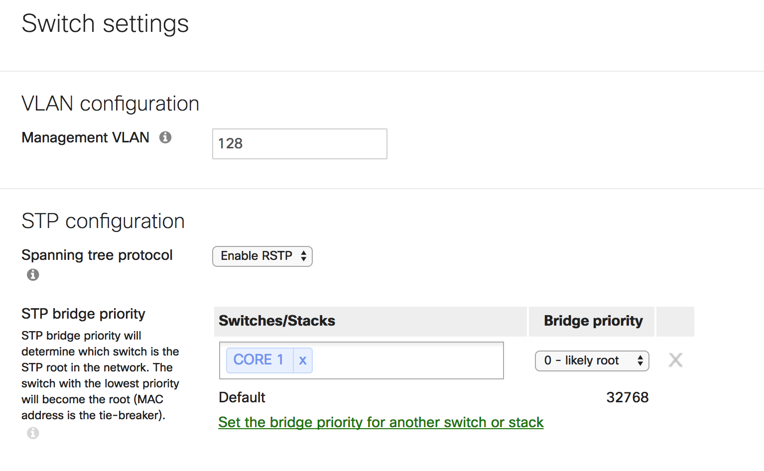
Make Catalyst the root switch
-
-
Set root switch priority to “0 - likely root”
-
Higher end models such as the MS410, MS425 deployed at core or aggregation are suitable candidates for the role
-
Ideally, the switch designated as the root should be one which sees minimal changes (config changes, link up/downs etc.) during daily operation
-
-
- Keep the STP diameter under 7 hops, such that packets should not ever have to travel across more than 7 switches to travel from one point of the network to the other
- BPDU Guard should be enabled on all end-user/server access ports to avoid rogue switch introduction in network
- Loop Guard should be enabled on trunk ports that are connecting switches
- Root Guard should be enabled on ports connecting to switches outside of administrative control
-
MTU
-
Recommended to keep at default of 9578 unless intermediate devices don’t support jumbo frames. This is useful to optimize server-to-server and application performance. Avoid fragmentation when possible.
-
-
Switchports
-
Trunk
-
Prune unnecessary VLANs off trunk ports using allowed VLAN list in order to reduce scope of flooding
-
Ensure that the native VLAN and allowed VLAN lists on both ends of trunks are identical. Mismatched native VLANs on either end can result in bridged traffic
Tagging
-
For ease of management, assign tags to switch ports. For example, switch<->switch links can be assigned “trunk”, switch<->AP can be “wireless” etc
-
-
Aggregation
-
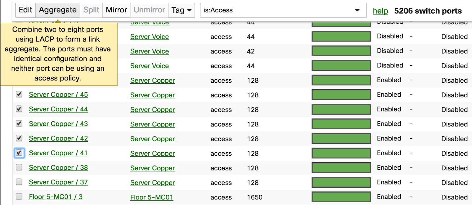
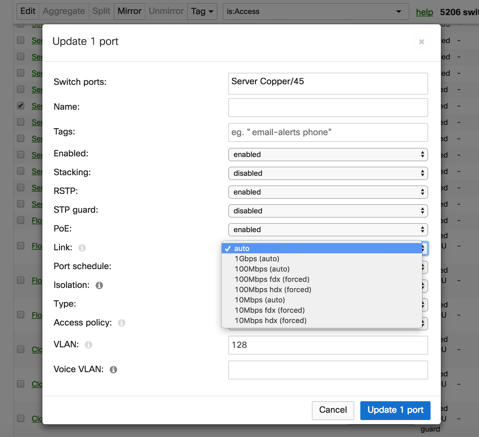
Only LACP is supported for link aggregation. Ensure the other end supports LACP
-
It is recommended to configure aggregation on the dashboard before physically connecting to a partner device
-
-
- UDLD (Unidirectional Link Detection)
- This should be enabled on fiber trunks - in “Alert Only” mode
- Link Negotiation
- This should be set to auto-negotiate for ports connecting Meraki devices
- Use “forced” mode only if a device connected to the port does not support auto-negotiation
- Switchport count in a network
- It is recommended to keep the total switch port count in a network to fewer than 8000 ports for reliable loading of the switch port page.
Layer 3 Features
- IP addressing and subnetting schema
- Dedicate /24 or /23 subnets for end-user access
- Avoid overlapping subnets as this may lead to inconsistent routing and forwarding
-
L3 Interfaces
-
Assign a dedicated management VLAN
-
Avoid configuring a L3 interface for the management vlan. Use L3 interfaces only for data VLANs. This helps in separating management traffic from user data
-
In case of switch stacks, ensure that the management IP subnet does not overlap with the subnet of any configured L3 interface. Overlapping subnets on the management IP and L3 interfaces can result in packet loss when pinging or polling (via SNMP) the management IP of stack members. NOTE: This limitation does not apply to the MS390 series switches.
L3 configuration changes on MS210, MS225, MS250, MS350, MS355, MS410, MS425, MS450 require the flushing and rebuilding of L3 hardware tables. As such, momentary service disruption may occur. We recommend making such changes only during scheduled downtime/maintenance window.
-
Access Control Lists (ACLs)
-
Summarize IP addresses as much as possible (before-after examples below).
-
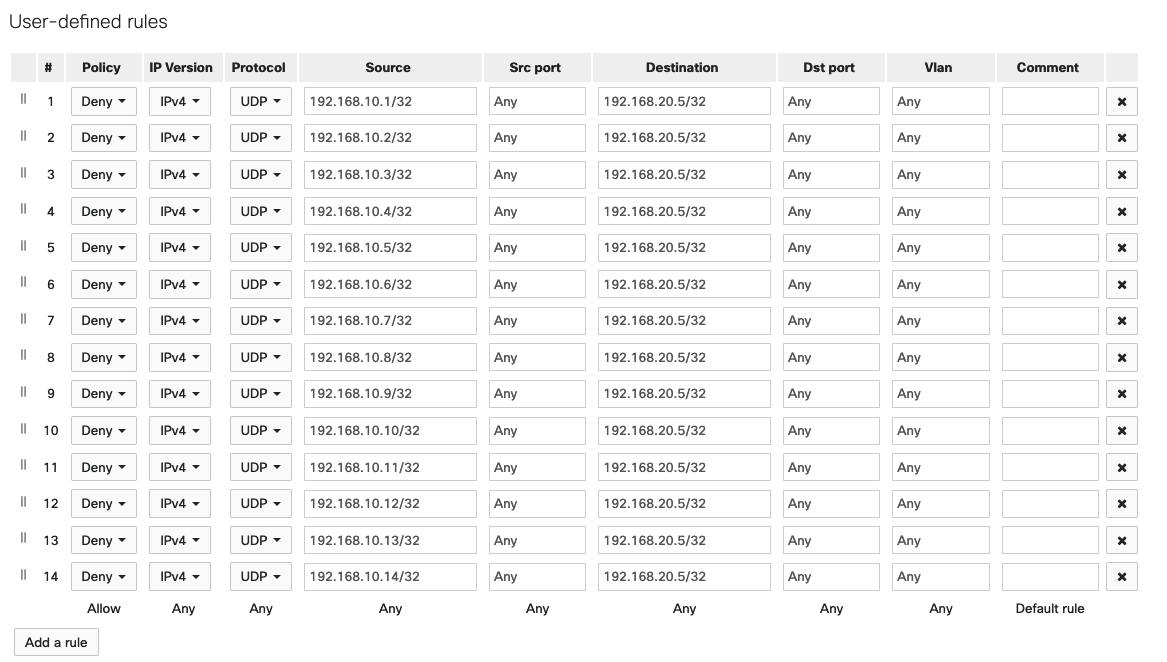

- Maximum ACL limit is 128 access control entries (ACEs) per network
Take control over your network traffic. Review user and application traffic profiles and other permissible network traffic to determine the protocols and applications that should be granted access to the network. Ensure traffic to the Meraki dashboard is permitted (Help > Firewall Info)
- OSPF
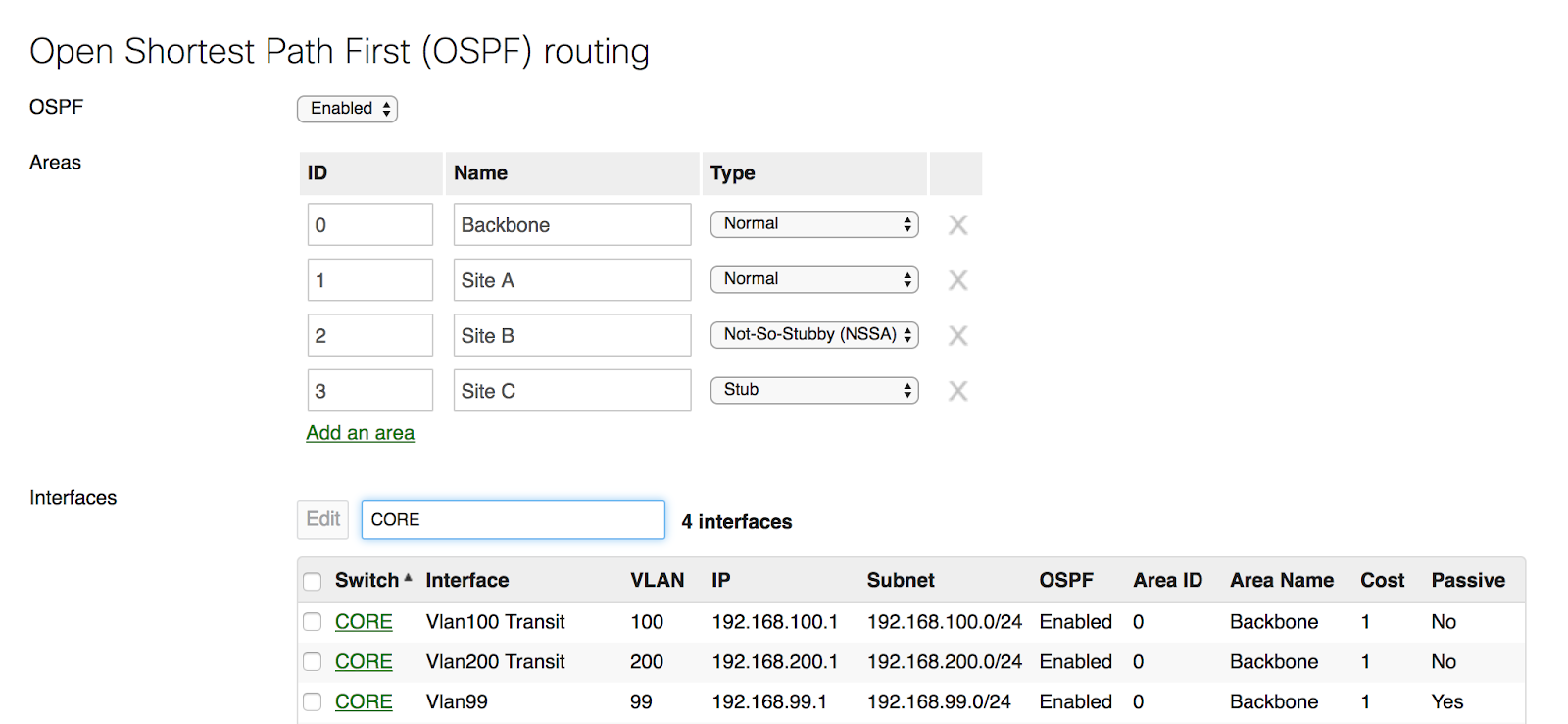
- Found under Switching > Configure > OSPF Routing
- All configured interfaces should use broadcast mode for hello messages
- We recommend leaving the “hello” and “dead” timers to a default of 10s and 40s respectively. If more aggressive timers are required, ensure adequate testing is performed.
- Ensure all areas are directly attached to the backbone Area 0. Virtual links are not supported
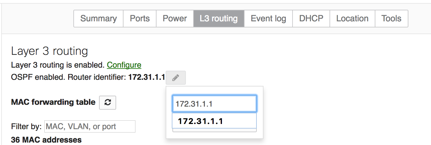
- Configure a Router ID for ease of management
- With multiple VLANs on a trunk, OSPF attempts to form neighbor relationships over each VLAN, which may be unnecessary. To exchange routing information, OSPF doesn’t need to form neighbor relationships over every VLAN. Instead, a dedicated transit VLAN can be defined and allowed on trunks, typically between the core and aggregation layers with OSPF enabled and “Passive” set to “no.” For all other subnets that need to be advertised, enable OSPF and set “Passive” to “Yes.” This will reduce unnecessary load on the CPU. If you follow this design, ensure that the management VLAN is also allowed on the trunks.
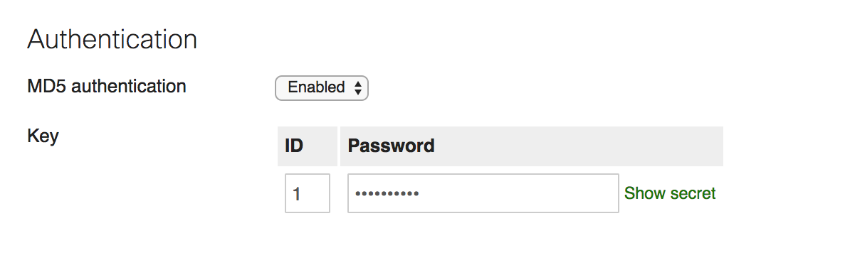
- Configure MD5 authentication for added security
-
DHCP
-
Specify allowed DHCP servers to protect against rogue servers
-
In a warm spare configuration, the load balancing mechanism for DHCP, in some case, may be inefficient and cause an issue where devices may try to get an address from a member with no leases remaining. This is addressed in a stacked configuration, where this issue will not occur.
-
Topology
- We highly recommend having the total switch count in any dashboard network to be less than or equal to 400 switches. If switch count exceeds 400 switches, it is likely to slow down the loading of the network topology/ switch ports page or result in display of inconsistent output.
Multicast
-
The most important consideration before deploying a multicast configuration is to determine which VLAN the multicast source and receivers should be placed in. If there are no constraints, it is recommended to put the source and receiver in the same VLAN and leverage IGMP snooping for simplified configuration and operational management.
-
Multicast Routing
-
Meraki switches provide support for 30 multicast routing enabled L3 interfaces on a per switch level
-
PIM SM requires the placement of a rendezvous point (RP) in the network to build the source and shared trees. It is recommended to place the RP as close to the multicast source as possible. Where feasible, connect the multicast source directly to the RP switch to avoid PIM’s source registration traffic which can be CPU intensive. Typically, core/aggregation switches are a good choice for RP placement
-
Ensure every multicast group in the network has an RP address configured on Dashboard
-
Ensure that the source IP address of the multicast sender is assigned an IP in the correct subnet. For example, if the sender is in VLAN 100 (192.168.100.0/24), the sender's IP address can be 192.168.100.10 but should not be 192.168.200.10.
-
Make sure that all Multicast Routing enabled switches can ping the RP address from all L3 interfaces that have Multicast Routing enabled
-
Configure an ACL to block non-critical groups such as 239.255.255.250/32 (SSDP). As of MS 12.12, Multicast Routing is no longer performed for the SSDP group of 239.255.255.250.
-
-
IGMP Snooping
-
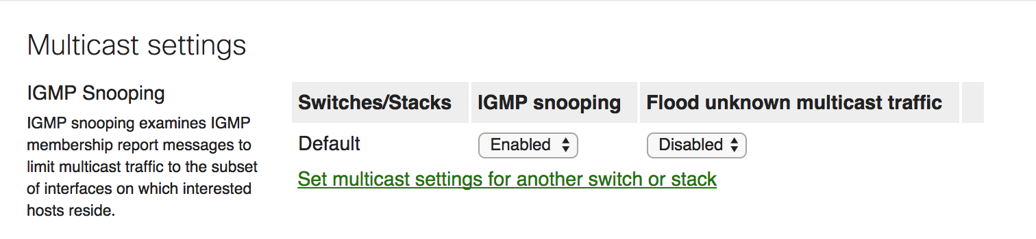
Disable IGMP Snooping if there are no layer 2 multicast requirements. IGMP Snooping is a CPU dependent feature, therefore it is recommended to utilize this feature only when required. For example, IPTV.
-
It is recommended to use 239.0.0.0/8 multicast address space for internal applications
-
Always configure an IGMP Querier if IGMP snooping is required and there are no Multicast routing enabled switches/routers in the network. A querier or PIM enabled switch/router is required for every VLAN that carries multicast traffic.
-
High Availability and Redundancy
Switch Stacking
The following steps explain how to prepare a group of switches for physical stacking, how to stack them together, and how to configure the stack in the dashboard:
-
Add the switches into a dashboard network. This can be a new dashboard network for these switches, or an existing network with other switches. Do not configure the stack in the dashboard yet.
-
Connect each switch with individual uplinks to bring them both online and ensure they can check in with the dashboard.
-
Download the latest firmware build using the Firmware Upgrade Manager under Organization > Monitor > Firmware Upgrades. This helps ensure each switch is running the same firmware build.
-
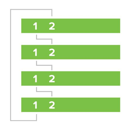
With all switches powered off and links disconnected, connect the switches together via stacking cables in a ring topology (as shown in the following image). To create a full ring, start by connecting switch 1/stack port 1 to switch 2/stack port 2, then switch 2/stack port 1 to switch 3/stack port 2 and so forth, with the bottom switch connecting to the top switch to complete the ring.
-
Connect one uplink for the entire switch stack.
-
Power on all the switches, then wait several minutes for them to download the latest firmware and updates from the dashboard. The switches may reboot during this process.
-
The power LEDs on the front of each switch will blink during this process.
-
Once the switches are done downloading and installing firmware, their power LEDs will stay solid white or green.
-
-
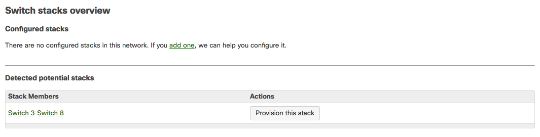
Navigate to Switching > Monitor > Switch stacks.
-
Configure the switch stack in the dashboard. If the dashboard has already detected the correct stack under Detected potential stacks, click Provision this stack to automatically configure the stack.
-
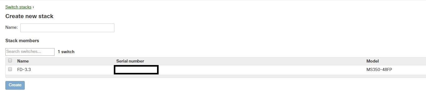
Otherwise, to configure the stack manually:
-
Navigate to Switching > Monitor > Switch stacks.
-
Click add one / Add a stack:
-
Select the checkboxes of the switches you would like to stack, name the stack, and then click Create.
The configuration is complete and the stack should be up and running.
- Use 2 ports on each of “top” and “bottom” switches of the stack for uplink connectivity and redundancy.
- Configure cross-stack link aggregation for uplink connectivity
Warm Spare for Layer 3 Switches
MS Series switches configured for layer 3 routing can also be configured with a “warm spare” for gateway redundancy. This allows two identical switches to be configured as redundant gateways for a given subnet, thus increasing network reliability for users.
Note that, while warm spare is a method to ensure reliability and high availability, generally, we recommend using switch stacking for layer 3 switches, rather than warm spare, for better redundancy and faster failover.
Warm Spare is built on VRRP to provide clients with a consistent gateway. The switch pair will share a virtual MAC address and IP address for each layer 3 interface. The MAC address will always begin with 00-00-5E-00-01, and the IP address will always be the configured interface IP address on the primary. Clients will always use this virtual IP and MAC address to communicate with their gateway.
-
For redundancy, ensure an alternate path exists for the exchange of VRRP messages between the Primary and Spare. A direct connection between the Primary and Spare is recommended
Any changes made to L3 interfaces of MS Switches in Warm Spare may cause VRRP Transitions for a brief period of time. This might result in a temporary suspension in the routing functionality of the switch for a few seconds. We recommend making any changes to L3 interfaces during a change window to minimize the impact of potential downtime.
Quality of Service
-
Classification
-
Identify different traffic classes within the network for prioritization. On a high level, traffic can be classified based on VLAN (user, voip, network control etc)
-
You can further classify traffic within a VLAN by adding a QoS rule based on protocol type, source port and destination port as data, voice, video etc.
-
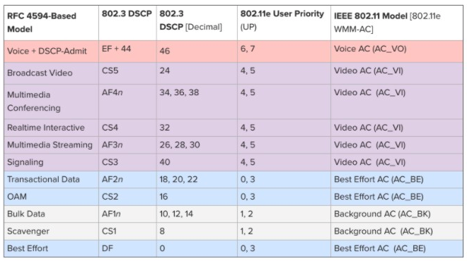
Typical enterprise traffic classes are listed below:
-
-
Marking
-
Meraki MS supports trusting or remarking of incoming DSCP values. Meraki MS supports marking (remarking/trusting) based on DSCP values only. CoS values carried within Dot1q headers are not acted upon. If the end device does not support automatic tagging with DSCP, configure a QoS rule to manually set the appropriate DSCP value.
-
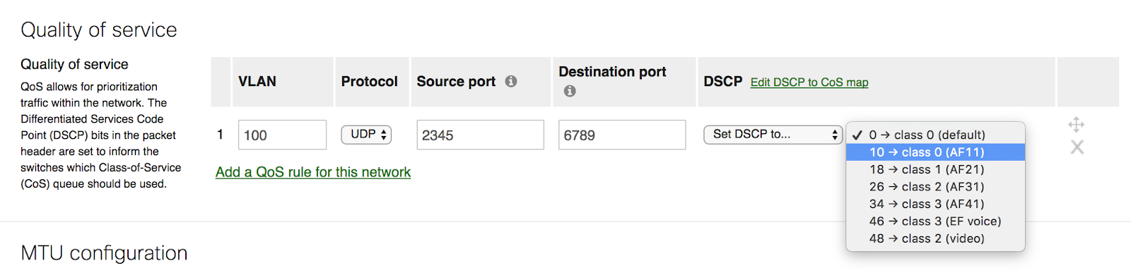
- CoS markings within a Dot1q header are not preserved by default since MS switches support DSCP markings only.
-
Queueing and Scheduling
-
Assign an appropriate Class-of-Service queue to each DSCP value
-
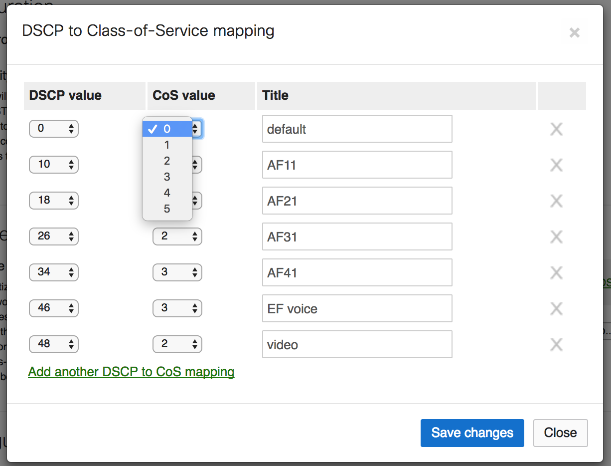
- An MS network has 6 configurable CoS queues labeled 0-5. Each queue is serviced using FIFO. Without QoS enabled, all traffic is serviced in queue 0 (default class) using a FIFO model. The queues are weighted as follows:
|
CoS |
Weight |
|
0 (default class) |
1 |
|
1 |
2 |
|
2 |
4 |
|
3 |
8 |
|
4 |
16 |
|
5 |
32 |
Take, for example, a switched environment where VoIP traffic should be in CoS queue 3, an enterprise application in CoS queue 2, and all of other traffic is unclassified. The percentage of bandwidth allocation can be calculated using the weight of the individual CoS queue as the numerator and the sum of all configured CoS queues as the denominator (in this example 8+4+1=13):
-
VoIP would be guaranteed 8/13 or ~62% percent of the bandwidth. The switch would forward 8 frames from the CoS queue 3 and move to CoS queue 2.
-
The enterprise application would be guaranteed 4/13 or ~30% bandwidth.The switch would forward 4 frames from the CoS queue 2 and move to the default queue.
-
All other traffic would receive 1/13 or ~8% of the bandwidth. The switch would forward 1 frame from the default queue, then cycle back to CoS queue 3.
Based on the information above, determine the appropriate CoS queue for each class of traffic in your network. Remember, QoS kicks in only when there is congestion so planning ahead for capacity is always a best practice.
Cabling Best Practices for Multi-Gigabit operations
While Category-5e cables can support multigigabit data rates upto 2.5/5 Gbps, external factors such as noise, alien crosstalk coupled with longer cable/cable bundle lengths can impede reliable link operation. Noise can originate from cable bundling, RFI, cable movement, lightning, power surges and other transient event. It is recommended to use Category-6a cabling for reliable multigigabit operations as it mitigates alien crosstalk by design.