
Meraki and Cisco Cloud Calling Connected Branch Solution
Introduction
In today’s digital transformation age, businesses are looking for collaboration, networking, security, and connectivity services that meet their needs. They are often challenged with a variety of complex solutions and providers to choose from. Managed Service Providers (MSPs) are in a unique position to deliver comprehensive solutions with managed networking and collaboration satisfying business needs and overcoming obstacles with over-the-top (OTT) services.
The purpose of this solution guide is to provide best practices on how MSPs can leverage Meraki’s cloud networking architecture and how Meraki networks should be configured and deployed, taking full advantage of the benefits offered by Cisco’s Cloud Calling platforms. This recommended network configuration is based on a Cisco-tested and -validated architecture optimized for the various Cloud Calling platforms such as Webex Calling and Cisco BroadWorks. The solution utilizes Cisco IP Phones with Multiplatform Firmware (MPP) as endpoints, and it focuses on branch deployments.
Recommendations provided in this document can serve as the basis to create a comprehensive solution that allows for rapid and seamless branch deployment, service continuity by leveraging SD-WAN technologies, as well as ease of management and troubleshooting. The solution enhances the user experience for end customers and providers by bringing together the best-of-breed in cloud-managed networking and collaboration.
The guide walks through some of the technical aspects of the solution and goes over the process of creating a network blueprint optimized for Cloud Calling platforms that can be used for new service creation allowing for consistency and standardization across end-customer sites. Guidance on how to operationalize the use of the blueprint network at scale is also provided in this document.
Key Benefits
There are several benefits that MSPs can gain from leveraging Meraki’s cloud networking architecture in conjunction with Cisco’s Cloud Calling platforms for branch deployments. Below is a list of the key benefits of this solution.
-
Mitigate over-the-top (OTT) related challenges
-
Eliminate manual phone provisioning processes
-
Based on Cisco’s blueprint network which is optimized for Cisco Cloud Calling platforms
-
Rapid and consistent site deployment
-
Intuitive and centralized cloud-based management
-
Additional visibility of endpoints, networks, and traffic usage for troubleshooting
-
Network intelligence and analytics
-
WAN monitoring and alerting for proactive response
-
Failover capabilities for service continuity
-
Built-in security and SD-WAN capabilities
Prerequisites
In order to deploy this solution, the following is required. Readers of this document should have:
-
Prior experience working the Cisco Meraki dashboard and Cisco Cloud Calling platforms, in addition to being familiar with the concepts and terminology of local area networking, SD-WAN, wireless, switching, and VoIP
-
Readers should have access to the Cisco Meraki dashboard; instructions on how to create a dashboard account and organization can be found in the Creating a Dashboard Account and Organization article
-
Access to the management portal for the Cisco Cloud Calling platform being used: Cisco Webex Calling or Cisco BroadWorks
-
Cisco Meraki devices along with their respective license keys; refer to table 1 (Appendix) for the specific device models, technical specifications, and sizing guide
-
Cisco Multi-Platform Phones (MPP). Technical specifications for the different models are available in the Cisco IP Phones with Multiplatform Firmware (MPP) article
-
Understanding of recommended dashboard structures for service providers as outlined in the Best Practices for Service Providers document
Overview of Deployment Architecture
This section provides an overview on how the solution is to be deployed by MSPs. It includes recommendations on how to structure the dashboard organizations, details on the network infrastructure to be installed at customer premises, as well as general guidelines on the customer provisioning process.
Recommended Dashboard Structure
MSPs generally have multiple customers in the same dashboard organization when delivering a standard service. Utilizing the standard service model (organization per service, network per customer) provides several operational benefits, however this structure should not be used if SD-WAN is being utilized as part of the service. This is because the scope of an organization defines the connectivity domain for Meraki Auto VPN, and it is important to keep customer deployments independent from each other in terms of connectivity. Generally, organizations for MSPs are separated in a one-organization-per-SD-WAN manner.
Given that this solution leverages Meraki Auto VPN and SD-WAN, each customer will need to be assigned to its dedicated organization. The recommended structure for this solution specifies the use of a base organization containing a blueprint network. This organization will serve as the foundation when creating independent organizations for new customer deployments, and each site is represented as a network under that customer’s organization. The structure is illustrated below.

Branch Network Infrastructure
The network equipment to be installed at customer premises will vary depending on the connectivity needs and amount of clients at each location. A general network diagram for a single customer deployment with two branch locations is available below. This can be scaled to multiple customer organizations each containing numerous branch networks.
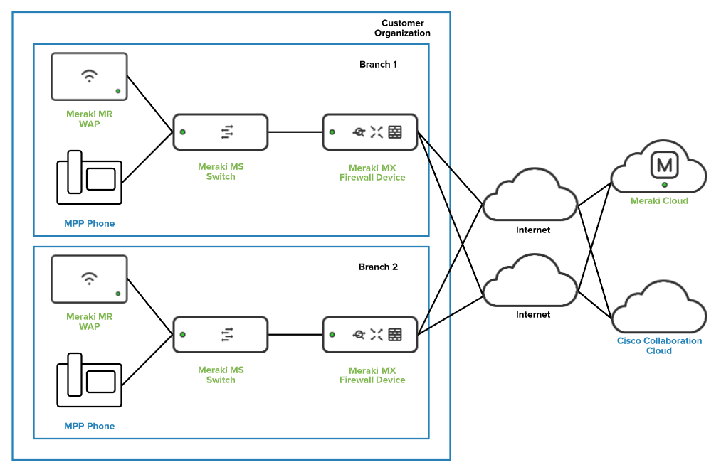
Specific device model information, technical specifications, and a sizing guide is available in table 1 of the Appendix.
Initial Setup and General Provisioning Workflow
In order to deploy this solution using the best practices provided in this document, the following workflows must be performed in order by the administrator.
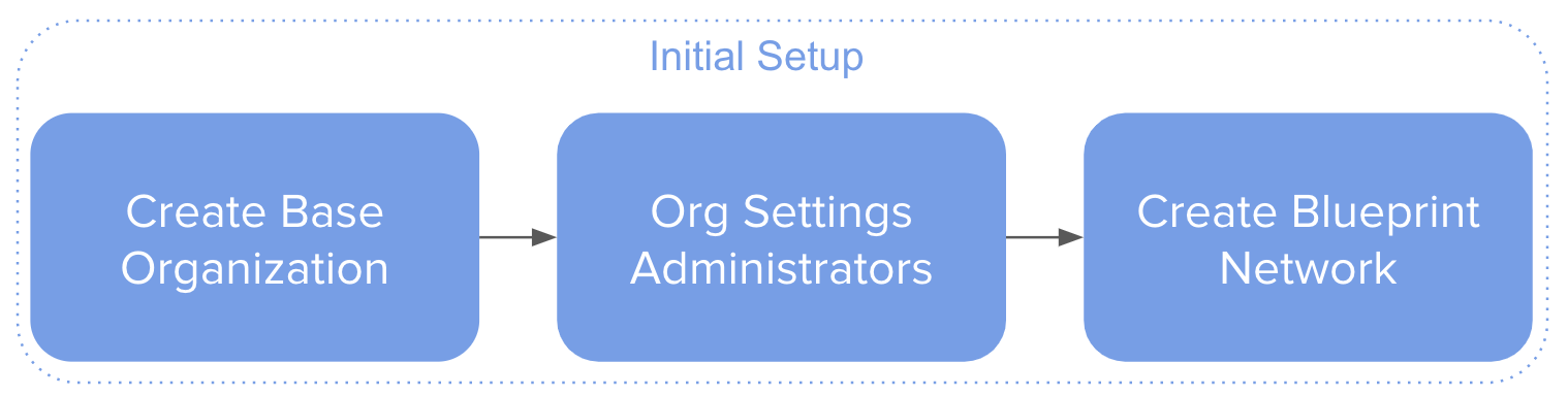
The initial setup consists of...
- Creating the base organization for the service
- Configuring the general settings for the organization
- Creating the blueprint network
After initial setup, when the base organization containing the blueprint network is available, administrators can follow the below workflow for provisioning purposes.
- Create a new organization by cloning the base organization
- Create a new network by cloning the blueprint network
- Add devices to the newly created network

A more detailed provisioning workflow is available in the “Automation of Network Provisioning” section of this document.
Creating and Configuring the Base Organization
A new organization can be created by following the instructions available in the Creating a Dashboard Account and Organization article,
Once the organization is created, the next step is to configure the following from the Organization > Settings page on the Meraki dashboard:
-
Enable SAML SSO (optional); additional information on how to configure this is available in the Configuring SAML Single Sign-on for Dashboard article
-
Enable dashboard API access; more information on the dashboard API is available in the The Cisco Meraki API document
-
Add relevant administrator accounts that will manage customer organizations; the Managing Dashboard Administrators and Permissions article describes the process of managing administrators
Note: It is important that all org settings that will be common to all customer organizations are configured on the base organization. The process of creating new customer organizations by cloning from the base org results in a child organization with all settings preconfigured.
Creating the Blueprint Network
This section walks through the process of creating the blueprint network that will serve as the base configuration for the network infrastructure and will be used as a starting point for new customer deployments. The blueprint network represents the Cisco recommended settings for successful deployments.
Note: It is required for the configuration to be applied to a configuration template in order to allow for it to be cloned from the base org onto new customer organizations.
Network Creation
After a dashboard account and organization have been created:
Step 1. Log in to the Cisco Meraki dashboard as an organization administrator.
Step 2. Select Configuration templates from the Organization tab.
Step 3. Click the Create a new template button.
Step 4. Enter a Template name and make sure it clearly describes its purpose (e.g.“Blueprint Network”) and click the Add button.
Step 5. Leave Target networks blank, click on the Close button, and Save changes.
Step 6. Navigate to the Organization tab and select Configuration templates. The newly configured template has been created and it is available for configuration.
Step 7. Click on the name for the template (e.g. Blueprint Network) to start configuring it.
Note: By default, the ability to create new networks by cloning from a configuration template (blueprint network) is not enabled. Please reach out to Meraki Support to have this functionality enabled on the base org. This process only needs to be performed once for the base org. Newly created organizations will inherit this functionality from the base org.
Network-Wide (General) Configuration
For the purposes of consistency, it is recommended to configure the general settings that are common across customer sites in the blueprint network. Below is a list of the most relevant settings available when selecting General under the Network-wide tab.
-
Country/Region sets the country of network; regulatory domain is set based on this
-
Local time zone sets the time zone of the network
-
Traffic analysis specifies the level of detail desired for traffic analysis
For added visibility, use the Detailed option for Traffic analysis. This enables collection of detailed information about the destinations which can be useful for troubleshooting.

Additionally, the Traffic analysis section allows for the definition of specific destinations to track and build a custom pie chart. The destinations can be defined based on HTTP hostname, Port, IP range, or IP range & port.

When a custom pie is configured and there is matching traffic to the destinations, traffic usage information will be available when selecting Clients from the Network-wide tab.

Security & SD-WAN (MX) Configuration
The configuration steps described in this section are specific to the Meraki MX Security appliances. The MX line has built-in security, SD-WAN capabilities, and is used in all the branch deployments as outlined in table 1 of the Appendix. Use the following steps to configure this portion of the reference network:
Step 1. Navigate to the Security & SD-WAN tab and select Addressing & VLANs
Step 2. From the Deployment Settings section of the page, ensure that the Routed and MAC address options are selected for the Mode and Client tracking settings respectively
![]()
Note: The Routed mode allows the MX to act as a Layer 3 gateway for the different subnets created, and all internet-bound client traffic will be translated (NAT). More information on this is available in the MX Addressing and VLANs article.
Step 3. Scroll down to the Routing section and enable the use of VLANs.
Note: Security appliances (MX) define the VLANs and subnets that exist in the branch network. It is best practice to ensure traffic is segregated by creating dedicated VLANs for voice, data, and guest traffic.
Step 4. Click on the Add VLAN button to create each of the VLANs needed for branch deployments.

-
Name: Use a name that describes the purpose of the VLAN (e.g. “Voice VLAN”).
-
Subnet: Defines the subnet to be mapped to the VLAN. Use Classless Inter-Domain Routing (CIDR) notation.
-
MX IP: The IP address within the subnet that the Security Appliance (MX) will use.
-
VLAN ID: The assignment of the VLAN tag. Use a number between 1 and 4,096.
-
Group Policy: Specifies the group policy to be applied to traffic within the subnet.
Step 5. Click Update after entering the VLAN information and confirm VLAN creation. Repeat the process for each of the VLANs needed.

Step 6. Navigate to the Security & SD-WAN tab and select DHCP. Each of the created subnets will have its own DHCP server configuration, ensure the Run a DHCP server drop-down option is selected for all VLANs.
Step 7. Scroll down to the DHCP server configuration for the Voice VLAN. In order to allow IP phones to retrieve configuration and a hosted phone firmware, add custom DHCP options entries with the following configuration:
-
Option: Select Custom from the drop-down to configure an unlisted DHCP option.
-
Code: Enter the number for the DHCP option (e.g. 150 for TFTP server address).
-
Type: Select Text.
-
Value: Enter the URL or IP address information.

Note: It is recommended to use at least two of the custom DHCP options to eliminate the need for manual phone provisioning. The sequence Cisco IP phones (MPP) use when booting up is: 66, 160, 159, 150
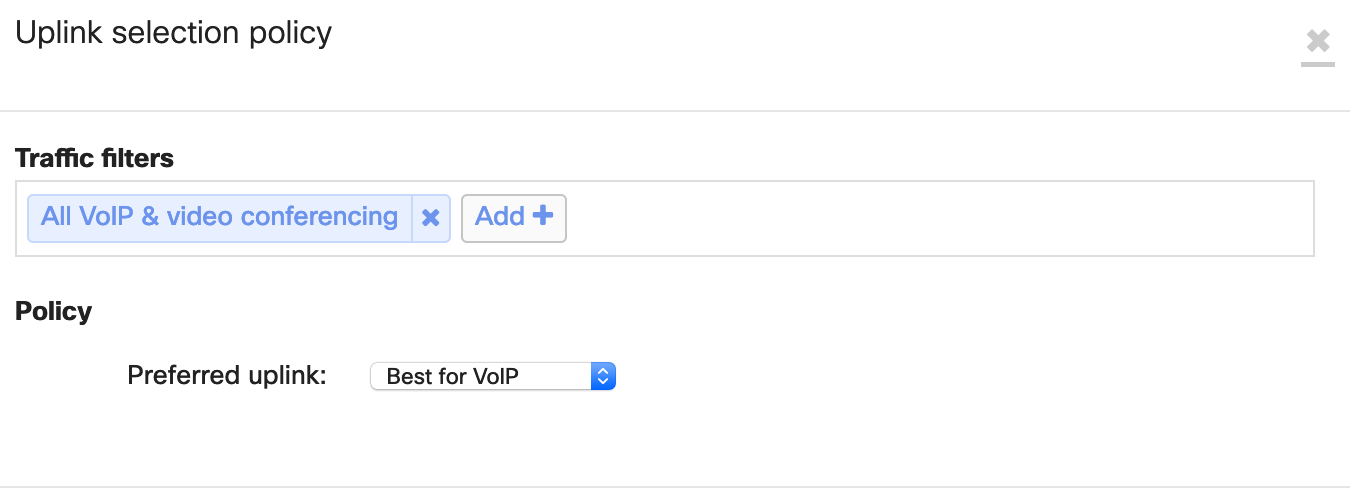
Step 8. Navigate to the Security & SD-WAN tab and select SD-WAN & Traffic shaping. Scroll down to the SD-WAN policies section and add a preference by using All VoIP & video conferencing under traffic filters and selecting Best for VoIP as the preferred uplink.
Step 9. Scroll down to Traffic shaping rules and configure a new rule for All VoIP & video conferencing traffic. Refer to the image below for additional details on how to configure the rule.

Switching (MS) Configuration
This section walks through the Meraki MS switching configuration portion of the blueprint network.
Step 1. Navigate to the Switch tab and select Switch settings.
Step 2. Scroll down to the Quality of service section of the page and create a new rule. Enter the voice VLAN ID, select Any protocol from the drop-down menu, and set the DSCP setting to Trust incoming DSCP.

Note: Switch port configuration is applied once devices are added to customer networks. This is covered in the Customer Provisioning section of this document.
Wireless (MR) Configuration
This section covers the Meraki MR wireless configuration piece of the reference network and it is only applicable to site deployments that leverage Cisco wireless phones. It is highly recommended to perform a pre-install RF survey as outlined in the Wireless VoIP QoS Best Practices document. Follow the next steps to configure the wireless settings of the blueprint network.
Step 1. Configure a dedicated SSID for voice by navigating to the Wireless tab and selecting SSIDs.
Step 2. Rename the default SSID. Use a name that describes its purpose (e.g. “CiscoVoIP”).
Step 3. Navigate to the Wireless tab and select Access control to configure the SSID.
Step 4. Configure the Network access section using a pre-shared key with WPA2 as the authentication method and WPA2 only as the WPA encryption mode.

Step 5. Scroll down to Addressing and traffic and select Bridge mode. In this mode, the Meraki MR access points will bridge the client directly to the LAN, and it is recommended for Layer 2 seamless roaming.

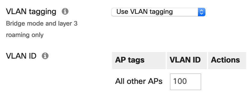
Step 6. Associate the dedicated voice SSID to the voice VLAN configured in the LAN by enabling VLAN tagging and specifying the ID for the voice VLAN used by the Meraki MX Security Appliance and Meraki MS switches.
Step 7. Scroll down to Wireless options and set the minimum bit rate to 12 Mbps. This is the recommended minimum bit rate for wireless networks with VoIP traffic. Disabling lower bit rates reduces overhead on the network and can result in an improved roaming experience.
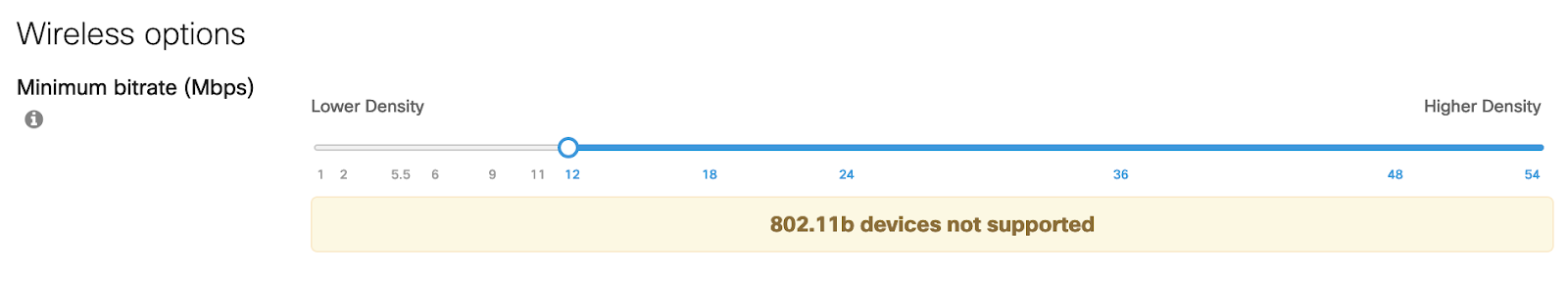
Note: Setting the bit rate to 12 Mbps and above will prevent 802.11b clients from joining the wireless network.
Step 8. Navigate to the Wireless tab and select Firewall & traffic shaping and ensure that the voice-dedicated SSID is selected from the drop-down.
Step 9. Scroll down to Traffic shaping rules and create a new rule for All VoIP & video-conferencing traffic and set the Per-client bandwidth limit to Ignore SSID per-client limit (unlimited).
Step 10. Set the PCP and DSCP tags to 6 and 46 (EF - Expedited Forwarding, Voice) respectively.
Note: The DSCP tag 46 (EF - Expedited Forwarding, Voice) maps to WMM Access Category AC-VO for Voice, Layer 2 CoS 6).
For additional information, refer to the Wireless VoIP QoS Best Practices document.
Meraki Insight
The Meraki Insight product is designed to give Meraki customers an easy way to monitor the performance of Web Applications and WAN Links on their network and easily identify if any issues are likely being caused by the network or application. The goal of Meraki Insight is to provide end-to-end visibility to customers and make sure they have assurance for the mission-critical traffic of the network.

Enabling and Disabling Meraki Insight
To Enable Meraki Insight on a network:
Step 1. Ensure the necessary licensing is available.
Step 2. Select the checkbox next to the network where Insight should be enabled.
Step 3. Click Add network(s) to Insight at the top left of the table to enable Meraki Insight on the selected network(s).
To Disable Meraki Insight on a network:
Step 1. Select the checkbox next to the network with Insight currently enabled.
Step 2. Click Remove network(s) from Insight
Configuring Meraki Insight for VoIP
After a dashboard account and organization have been created:
Step 1. Log in to the Cisco Meraki dashboard.
Step 2. Select VoIP Health from the Insight tab.
Step 3. Select Configure VoIP servers on the pop-up.
Step 4. Input the Provider name and the Hostname or IP. Repeat this step to add additional VoIP servers.
Note: VoIP Health supports monitoring for on-premises VoIP servers that are available on the LAN or over VPN.
Monitoring Meraki Insight for VoIP
Once you provide the servers you’d like to monitor, you’ll be able to see an org-wide view of performance:
Step 1. Select VoIP Health from the Insight tab.

Clicking any row will take you to a drill-down view with detailed performance information:

For further details regarding the capabilities of Meraki Insight, see the Meraki Insight Introduction article.
Automation of Network Provisioning
The Meraki dashboard offers a robust set of APIs enabling automated network provisioning and deployment. Prior to utilizing the APIs, they must be enabled for an account, and a specific user must have an API key. In general, it is recommended that a dedicated dashboard administrator account be created for use of APIs, and the API key generated for that user.
Initial Setup
In order to automate the network provisioning, some initial steps must be performed:
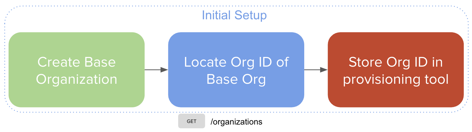
Step 1. Create the base organization (see Creating and Configuring the Base Organization above).
Step 2. Locate the organization ID for the base organization.

Step 3. Configure the provisioning tool with the located organization ID.
Customer Provisioning
Once the provisioning system has been configured, new customers can be deployed using the following steps:

Step 1. New customer order is placed, automated network provisioning begins.
Step 2. Create a new organization, cloning from the base organization.
Step 3. Locate the network ID for the network that corresponds to the blueprint network.

Step 4. Create a new network by cloning from the blueprint network.

Step 5. Add hardware to newly created network.

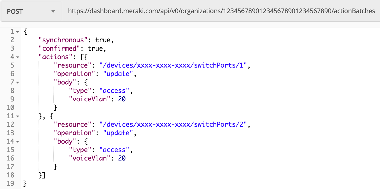
Step 6. Configure switch ports for voice services (access port and voice VLAN). As a general recommendation, you should utilize the Action Batches API documentation to perform this task.
Appendix
Table 1 - Cisco Meraki devices technical specifications and sizing guide
|
Micro Site (Up to 7) |
Small Site (Up to 25) |
Medium Site (25-100) |
Large Site (100-250) |
|
|
Security & SD-WAN (MX) |
||||
|
MX Model |
MX68CW (Branch in a Box) |
MX67/MX67C |
MX84 |
MX100 |
|
Stateful Firewall Throughput |
450 Mbps |
450 Mbps |
500 Mbps |
750 Mbps |
|
Advanced Security Throughput |
300 Mbps |
300 Mbps |
320 Mbps |
650 Mbps |
|
WAN Interfaces (dedicated) |
2 x GbE RJ45 |
1 x GbE RJ45 |
2 x GbE RJ45 |
2 x GbE RJ45 |
|
Dual-Purpose (WAN/LAN) |
- |
1 x GbE RJ45 |
- |
- |
|
LAN Interfaces |
10 x GbE RJ45 (2 x PoE+) |
4 x GbE RJ45* |
8 x GbE RJ45 2 x SFP |
8 x GbE RJ45 2 x SFP |
|
LTE Failover |
Yes |
Yes |
Yes (USB) |
Yes (USB) |
|
* One of the LAN ports is optionally available for WAN connectivity |
||||
|
Switching (MS) |
||||
|
MS Model |
MS120-8LP (Optional) |
MS120-24P, MS120-48FP |
MS120-48FP |
MS120-48FP |
|
Interfaces |
8 x GbE |
24/48 x GbE |
48 x GbE |
48 x GbE |
|
Uplinks |
2x 1G SFP |
4 x SFP |
4 x SFP |
4 x SFP |
|
PoE/PoE+ |
67W |
370W/740W |
740W |
740W |
|
Wireless (MR) - Optional |
||||
|
MR Model |
- |
MR33 |
MR42 |
MR42 |
|
Wi-Fi Generation |
N/A |
Wi-Fi 5 (802.11ac) |
Wi-Fi 5 (802.11ac) |
Wi-Fi 5 (802.11ac) |
|
Radio |
- |
2x2:2 MU-MIMO |
3x3:3 MU-MIMO |
3x3:3 MU-MIMO |
|
Max Throughput |
- |
1.3 Gbps |
1.9 Gbps |
1.9 Gbps |
Note: The recommended models for sizing are based on models available at the time of publication for this document. This list will not be updated with new models. For the most up-to-date sizing guide information, please refer to the Meraki MX Sizing Guide.