
Deploying Catalyst Switches as the Core of a Meraki Adaptive Policy Switching Network
Overview
Adaptive Policy’s underlying technology relies on inline Security Group Tagging (SGT) to perform security policy implementation from a single switch or access point to an entire network infrastructure. In many environments the network has been standardized with Catalyst switching in the core of the network and Meraki MS switching in the distribution and access layer. Meraki Adaptive Policy was built to provide interoperability with any infrastructure that can support inline SGTs. The following document will review configuration considerations and requirements to successfully deploy Catalyst switches as the core of an Adaptive Policy network.
Requirements for Interoperability
For Adaptive Policy to operate in conjunction with a traditional TrustSec enabled device, there are a few requirements for Meraki and Catalyst hardware and software.
Meraki Requirements
The Meraki switches in the network must be adaptive policy capable models running the latest version of firmware (CS15+ or MS17 for the MS130).
Catalyst Requirements
The Cisco Catalyst switches must support inline SGTs. The list of Catalyst switches that support inline SGTs can be found in the TrustSec Capability Matrix.
The recommended code release for the Catalyst switches depends on the model of switch selected (e.g. Cisco Catalyst 9500 running IOS-XE 16.12.2). See the TrustSec Capability Matrix for more details.
Topology Requirements
Aside from hardware and software requirements, the network design has a few requirements:
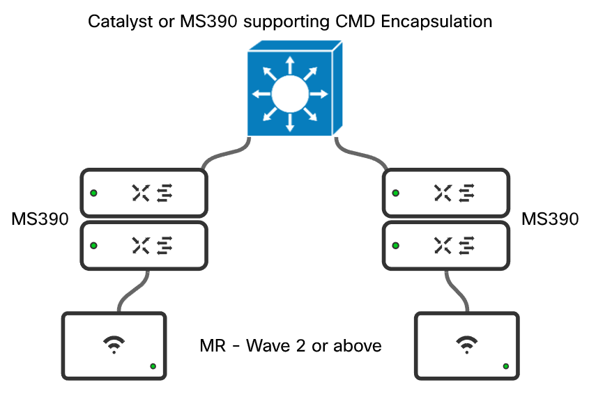
- No transit devices in between inline SGT nodes that do NOT support inline SGTs. Inline SGTs are carried using an encapsulation called Cisco MetaData (CMD). CMD encapsulation support is an ASIC level functionality that may or may not transit a switch that does not understand the Ethertype.
- Policy is enforced at the destination. Given this is the case, the entire path from source to destination must support CMD encapsulation through the network.
An example of a correct design is shown below:
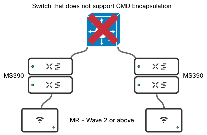
An example of a incorrect design is shown below:
Catalyst (IOS-XE) Configuration to Support SGT Transit
In an IOS-XE switching environment, only a small amount of configuration is needed to allow SGTs to transit the switch. If the switch is being used as an aggregation or core without direct client connectivity, the switch should not need to perform any enforcement or take on any enforcement configurations.
IOS-XE Global Configuration
From a global switch perspective the following configuration should be in place:
configure terminal
!
cts sgt 2
!!!!sets the system/infrastructure sgt
cts role-based enforcement
!!!!enables SGT policy globally on the switch
cts role-based enforcement vlan-list <vlan-list>
!!!!enables SGT policy on the specific VLANs
!
ip access-list role-based Permit_Any
 permit ip
!!!!creates a global default permit policy
!
cts role-based permissions default Permit_Any
!!!!sets the default policy to the SGACL configured above
!
exit
IOS-XE Trunk Port Configuration
The Catalyst interfaces that are connected to a Meraki MS or MR where inline SGTs are supported will need to be configured in the following manner:
configure terminal
!
interface <interface>
description <link-connectivity-description>
switchport mode trunk
switchport trunk native vlan <native-vlan>
switchport trunk allowed vlan <vlan-list>
cts manual
!!!!Enables SGT encapsulation and will bounce the port
 policy static sgt 2 trusted
 !!!Sets the port to an infrastructure trusted port
no cts role-based enforcement
!!!!Disables enforcement on the port allowing for enforcement to happen downstream
!
exit
With the configuration on the interface above the following will occur:
- If a frame is received with an SGT assigned, the switch will honor that tag.
- If a frame is received with no encapsulation it will be encapsulated and marked 0 - Unknown**.
- No policy enforcement will occur inbound on this port.
- This is desired to make sure that policy is enforced where the destination endpoint is attached.
** This will depend on the platform.
Meraki Uplink Configuration
In the Meraki dashboard, perform the following configurations:
- Verify the network has Adaptive Policy enabled under Organization > Adaptive Policy > Networks
- For the interface connected to the catalyst switch configure the following:
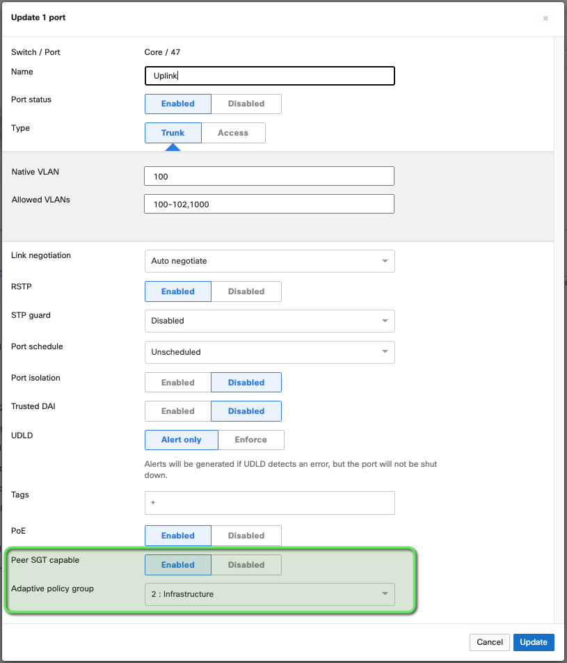
- Type: Trunk - Required for SGT propagation to be configured
- Peer SGT capable: Enabled - Turns on CMD encapsulation
- Adaptive Policy Group: 2: Infrastructure - enables a peer to peer tag of 2 (standard infrastructure to infrastructure tag) This is a best practice for all tag based security deployments.
Note: When you click save, the interface will cycle down and then back up
Testing and Validation
Using Meraki Dashboard Tools
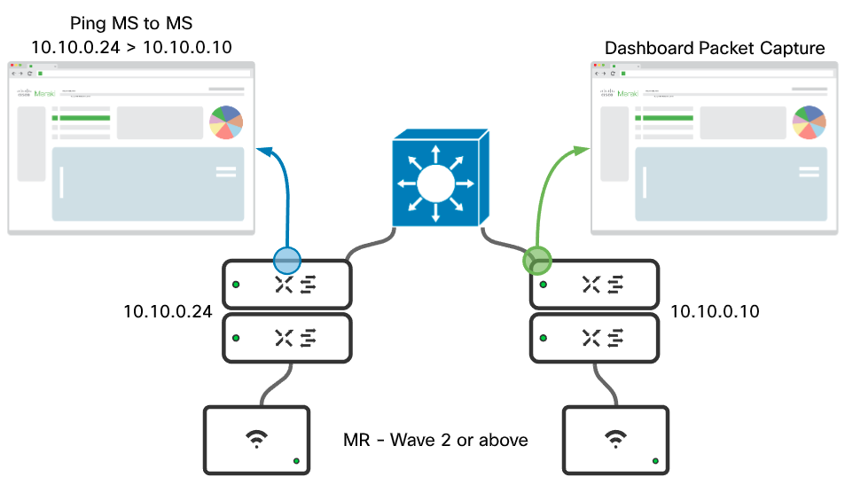
A simple ping (ICMP) can be used to test and validate that tags are making it through the core device. To do this, ping through the core and perform a packet capture on the destination uplink port, as shown in the example below. Once the capture is complete inspect in Wireshark.
Example:
Correct output:
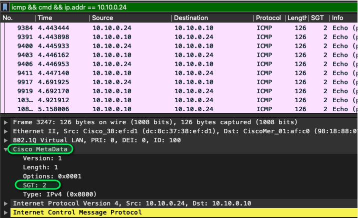
To validate the tag has made it through the environment the follow needs to be performed in the packet capture:
-
Select an ICMP packet with the correct source and destination IPs.
-
Expand the Cisco MetaData field in the packet.
-
Ensure that the tag (as highlighted above) is 2. If the tag is 0 there is a configuration error and a port by port configuration check is necessary
For a handy wireshark filter: “icmp && cmd.sgt == {sgt) && ip.addr == {source switch}”
Example: “icmp && cmd.sgt == 2 && ip.addr == 10.10.0.24”
Using Catalyst local Packet Capture
In IOS-XE there is the ability to perform packet captures directly on the switch using a functionality called "Monitor Capture". This allows you to capture packets on interfaces whether virtual or physical and either inspect locally on the switch or export to inspect in Wireshark.
To validate if the switches attached to the catalyst core are sending CMD encapsulated traffic perform the following configurations from privilege exec mode:
monitor capture {Name} match any
monitor capture {Name} interface {interface connected to meraki managed switch} both
monitor capture {Name} limit packets {number of packets}
monitor capture {Name} buffer size {number of MB}
monitor capture (Name} start
Example:
monitor capture CMD match any
monitor capture CMD interface Gigabitethernet 1/0/13 both
monitor capture CMD limit packets 10
monitor capture CMD buffer size 2
monitor capture CMD start
If the connectivity is via console there will be an output like the following:
switch#monitor capture CMD start
Started capture point : CMD
Apr 17 22:27:26.633: %BUFCAP-6-ENABLE: Capture Point CMD enabled.
Apr 17 22:27:28.642: %BUFCAP-6-DISABLE_ASYNC: Capture Point CMD disabled. Reason : Packet Count Reached
If the connectivity is through SSH or telnet the following command can be issued to see when the packet capture stops of:
terminal monitor
or the following command can be run to check the status of the capture:
show monitor capture {Name}
and an example output would be:
switch#show monitor capture CMD

Status Information for Capture CMD
  Target Type:
 Interface: GigabitEthernet1/0/13, Direction: BOTH
   Status : Inactive
  Filter Details:
    Capture all packets
  Buffer Details:
   Buffer Type: LINEAR (default)
   Buffer Size (in MB): 2
  Limit Details:
   Number of Packets to capture: 10
   Packet Capture duration: 0 (no limit)
   Packet Size to capture: 0 (no limit)
   Maximum number of packets to capture per second: 1000
   Packet sampling rate: 0 (no sampling)
Once the packet capture has completed there are two options to validate tagging:
- Run a local command of:
show monitor capture {Name} buffer detailed
Example output (looking for the section after 802.1q of Cisco MetaData:
switch#show monitor capture CMD buffer detailed
Starting the packet display ........ Press Ctrl + Shift + 6 to exit
Frame 1: 170 bytes on wire (1360 bits), 170 bytes captured (1360 bits) on interface 0
    Interface id: 0 (/tmp/epc_ws/wif_to_ts_pipe)

~~~~~Truncated to reduce size ~~~~~~~~~~~~~~~

802.1Q Virtual LAN, PRI: 6, CFI: 0, ID: 101
    110. .... .... .... = Priority: Voice, < 10ms latency and jitter (6)
    ...0 .... .... .... = CFI: Canonical (0)
    .... 0000 0110 0101 = ID: 101
    Type: CiscoMetaData (0x8909)
Cisco MetaData
    Version: 1
    Length: 1
    Options: 0x0001
    SGT: 6
    Type: IPv4 (0x0800)
Internet Protocol Version 4, Src: 10.10.1.201, Dst: 69.12.170.4
    0100 .... = Version: 4
    .... 0101 = Header Length: 20 bytes (5)
    Differentiated Services Field: 0xc0 (DSCP: CS6, ECN: Not-ECT)

~~~~~ truncated to reduce size ~~~~~~~~~~~~~~~~~~
- Run the following command to export to an external server on 17.X and later:
monitor capture {Name} export {bootflash:/ | crashinfo:/ | flash:/ | ftp:/ | http:/ | https:/ | rcp:/ | scp:/ | sftp:/ | tftp:/}/{filename.pcap}
Example:
switch#monitor capture CMD export tftp://10.10.1.11/pcap.pcap
- On pre 17.X firmware the buffer has to be saved to flash before being exported to a server
example:
switch#monitor capture CMD export location flash:/pcap.pcap
switch#copy flash:/pcap.pcap tftp://10.10.1.11/
Walkthrough example of pre 17.X:
To verify packets are encapsulated a simple wireshark filter of "cmd" can be used. Then identify a client plugged into the Meraki managed switch and validate the source tag is present like in the above GIF.