

Using Packet Capture to Troubleshoot Client-side DHCP Issues
Overview
This article describes how to use the Packet Capture tool in the Meraki dashboard to troubleshoot client-side DHCP issues on your network. Install Wireshark before opening the packet capture (PCAP) file downloaded from the dashboard. In this example, a client device connects to a Cisco Meraki MS switch port but cannot obtain an IP address from the DHCP server.

Figure 1: DHCP Handshake.
Troubleshooting DHCP client connectivity issue
A client device connects to a Meraki MS switch port but cannot obtain an IP address from the DHCP server. The two most common problems are:
- The client device never receives a response from the DHCP server.
- The client device receives an IP address from the wrong DHCP server.
For the second issue, refer to the following KB article: Tracking down a rogue DHCP server.
Troubleshooting steps
- Navigate the Packet capture tool in the dashboard
- Follow these steps based on your network type:
- For a standard network: Navigate to Monitor > Packet capture.
- For a combined network: Navigate to Network-wide > Packet capture, then select the Meraki appliance from which you want to capture traffic.

Figure 2: Screenshot of the Packet Capture tool interface in the Meraki dashboard, showing options to select a device and port for capturing network traffic
- Configure and start the packet capture
Exception: If the DHCP server connects to the same switch as the client, capture from the specific port the client connects to instead of the uplink port.
- Configure the Packet Capture tool with the following settings:
- Set the capture source to the switch uplink port and the client on the same switch.
- Set the Output to PCAP.
- Set the Capture duration to 60 seconds.
- Select Start capture to run the packet capture.

Figure 3: Screenshot of the Meraki dashboard showing a configured packet capture session on a specific switch port, with duration and file format settings visible.
- Force a DHCP broadcast from the client machine
- These commands force the client machine to send a DHCP broadcast:
- Open Command Prompt on the client machine.
- Run the following commands:
- ipconfig /release
- ipconfig /renew
- Repeat these commands several times to generate enough traffic for the capture tool to record.
Figure 4: Screenshot of the output of the IP release and renew commands in Command Prompt
- Analyze the PCAP file in Wireshark
- In Wireshark, open the PCAP file you downloaded from the dashboard.
- Enter the bootp display filter in the filter bar.
- Click Apply.
The bootp filter displays all stages of the DHCP process in the capture:
- DHCP Discover
- DHCP Offer
- DHCP Request
- DHCP Acknowledge
The Transaction ID groups each DHCP handshake together and identifies which messages belong to each handshake.

Figure 5: Packet capture illustrating the DHCP handshake
- Validate the packet capture results
- In the capture, confirm the following:
- The client device sends a Discover broadcast.
- The DHCP server responds to the client.
- The following figures illustrate expected capture results:
- Figure 6 shows the client device (Source: f0:de:f1:a3:5d:d6) sending a broadcast to Destination: ff:ff:ff:ff:ff:ff.

Figure 6: Wireshark screenshot highlighting a DHCP Discover message, showing the client MAC address as the source and the broadcast address ff:ff:ff:ff:ff:ff as the destination.
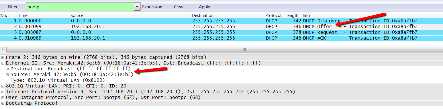
Figure 7: Wireshark screenshot highlighting a DHCP Offer packet, showing the DHCP server MAC address as the (Source: 00:18:0a:42:3e:b5) and the client MAC address as the destination.
Investigate if no server response appears
If you are not seeing a response back, here are some other things worth looking into:
- Verify 802.1q is correct setup on the Switch port.
- Ensure the switches uplink has the correct allowed VLANs if using VLANs and VTP within your infrastructure.
- Run packet captures off your other devices along the path between the client and the DHCP server
- Run wireshark on your DHCP server to verify you are seeing the clients DHCP discover making it to your server and that the response has the correct destination MAC address.
- Check routing setup on your Layer 3 devices to ensure the client has the correct path setup to the DHCP server.
- Review the DHCP server for leases problems, exhausted DHCP pool or out right DHCP services issues.
Applying these troubleshooting steps to other Meraki devices
You can apply these troubleshooting steps to other Meraki devices as follows:
MX WAN appliance:
- Configure the Packet Capture tool to capture from the LAN side of the MX.

Figure 8: Screenshot of the Meraki dashboard showing the Packet capture tool configured to capture traffic on the LAN interface of an MX WAN appliance.
MR access point:
Capture location depends on the SSID mode:
- If the SSID runs in bridge mode, capture from the wired connection.

Figure 9: Screenshot of the Meraki dashboard showing the Packet capture tool configured to capture wired traffic for an MR access point running in bridge mode.
If your SSID is configured to run in NAT mode you will want to setup your capture on the Wireless portion

Figure 10: Screenshot of the Meraki dashboard showing the Packet Capture tool configured to capture wireless traffic for an MR access point running in NAT mode.