MG21E Cellular Patch Antenna Datasheet
.png?revision=1&size=bestfit&width=466&height=619)
The Cellular Patch Antenna (MA-ANT-C1-B) is ideal for situations that require higher directional gain towards a cellular tower. When mounted high up on a pole for a clearer line of site toward a cellular tower, the MG cellular gateway will have higher signal quality and power.
Specifications
| Category | Specifications |
| Electrical |
Antenna Type: Narrow Patch Frequency Range:
Peak Gain (per range):
Polarization: Linear, Horizontally (left) and Vertically (right) Beamwidth (horizontal): 60° Beamwidth (vertical): 60° |
| Cables | Length: 100cm |
| Mounting | Mounts to walls and poles |
| Physical and Environmental |
Dimensions: 220mm x 220mm x 46mm Weight: 550g Material: PC-ABS Temperature: -40°C to +85°C (-40°F to 185°F) Humidity: 95% at 55°C (131°F) Connector: RP-SMA |
| Warranty | 1 year hardware warranty included |
| Ordering Information | MA-ANT-C1-B (works with MG21E only) |
| Regulatory | Certified for use with the MG21E: MA-ANT-C1-B |
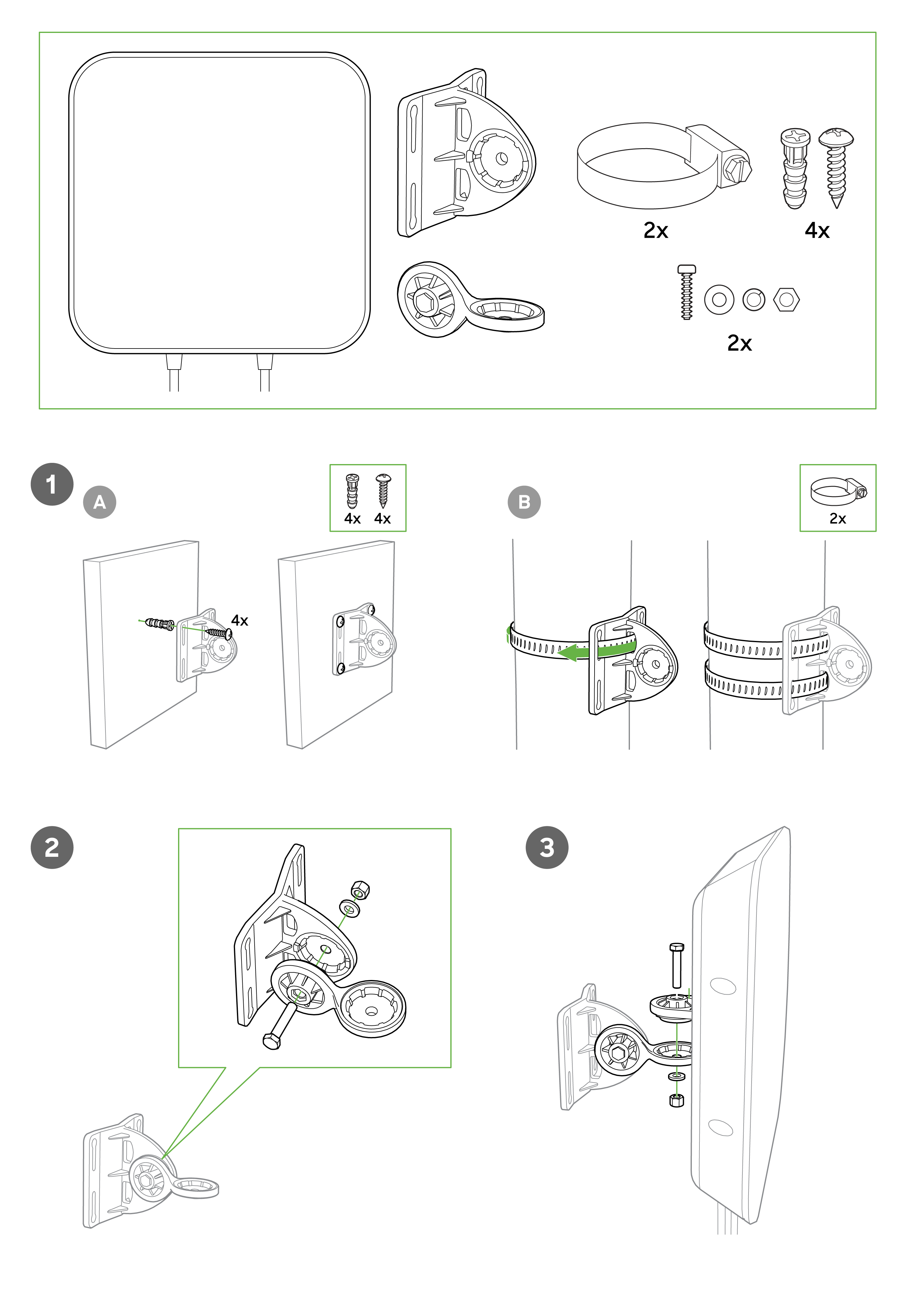
The mounting hardware bracket is included with the patch antenna. No other accessories are required to mount.
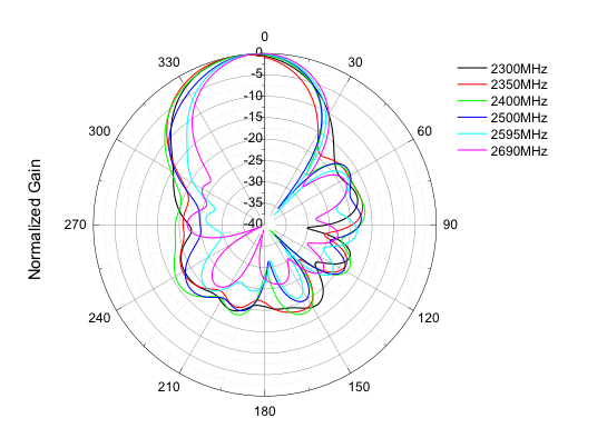
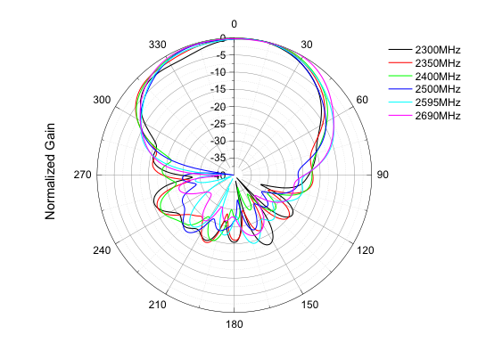
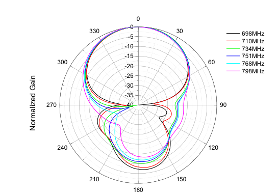
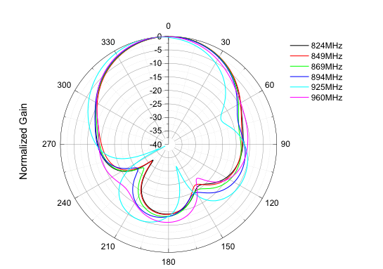
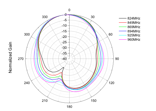
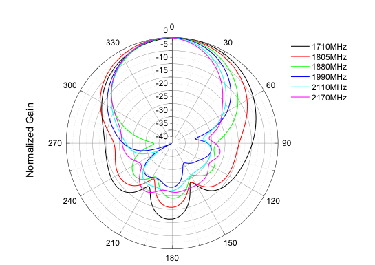
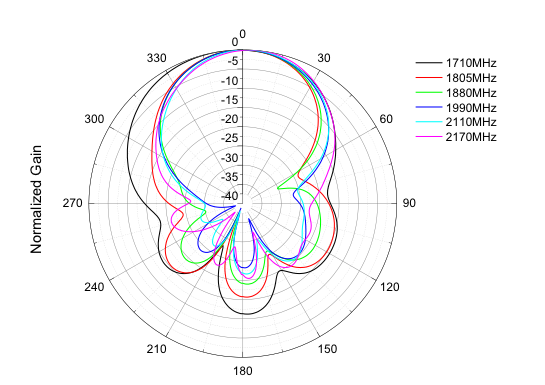
Radiation Patterns
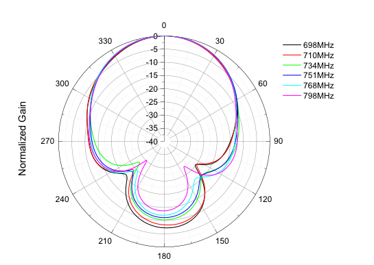
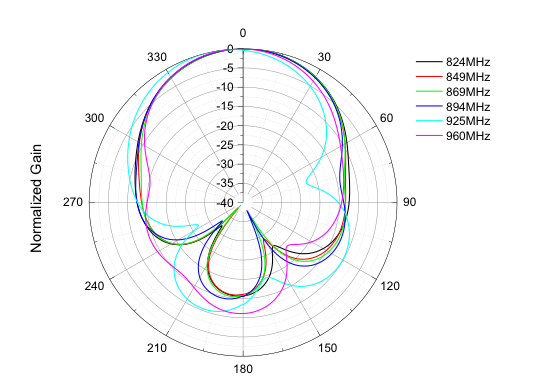
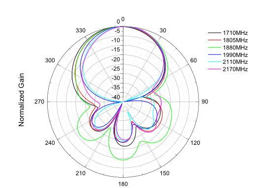
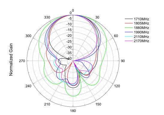
H-Port (Left, port 2): H-plane & V-plane
700 (698 - 791) MHz
960 (824 - 960) MHz

2170 (1710 - 2170) MHz
2690 (2570 - 2690) MHz
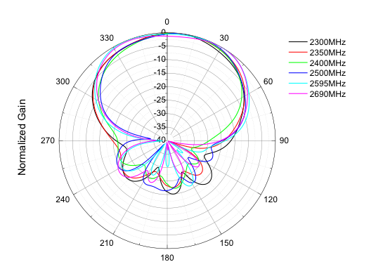
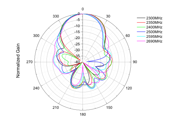
V-Port (Right, port 1): H-plane & V-plane
700 (698 - 791) MHz
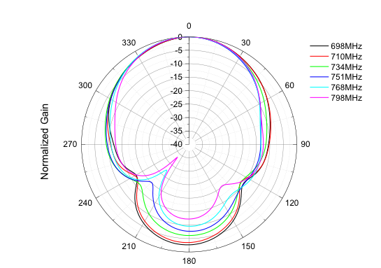
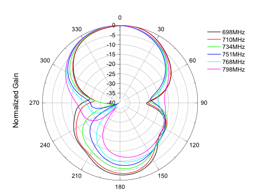
960 (824 - 960) MHz
2170 (1710 - 2170) MHz
2690 (2570 - 2690) MHz
