
SSID Tunneling and Layer 3 Roaming - VPN Concentration Configuration Guide
Meraki and Cisco Wireless access points may be configured to concentrate traffic to a single point either for Layer 3 roaming or Teleworker VPN use cases. Teleworker VPN and Layer 3 roaming with a concentrator both use the same Meraki Auto VPN technology. Wireless access points should concentrate to a Meraki MX security appliance.
It is recommended that a separate network be created in Dashboard for each remote site location for purposes of manageability and usage tracking. Remote site networks should be created and access points added to the networks using the Quick Start guide. Get started by selecting “Create a network” from the network selector in Dashboard.
SSID Configuration
Configuring an SSID to concentrate to an MX security appliance is simple for both Layer 3 Roaming and VPN Concentrator modes.
SSIDs are automatically moved to 'Bridged' mode to provide continuity of connectivity if the MX terminating the tunnel is removed from its dashboard network.
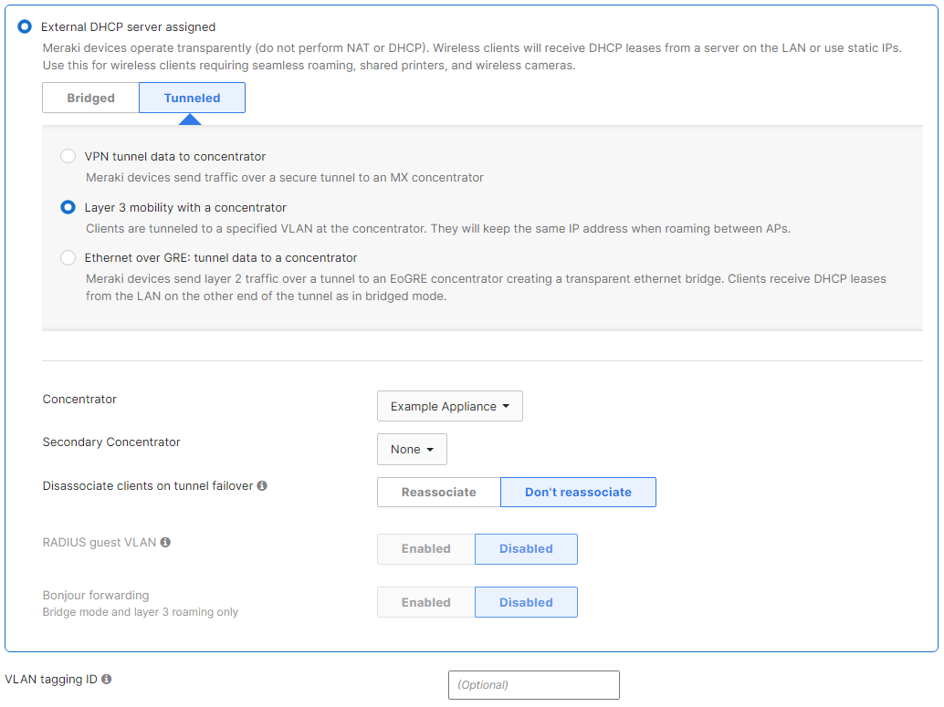
1) Navigate to Wireless > Configure > Access control > Client IP and VLAN and select External DHCP server assigned
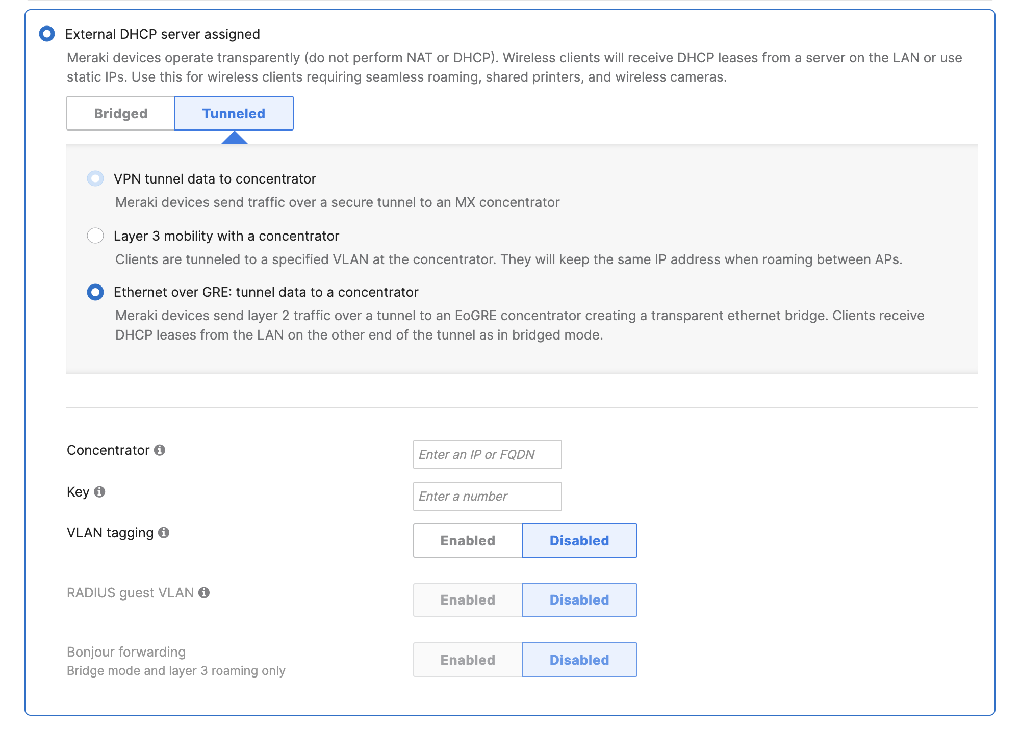
2) Click Tunneled, and select either VPN tunnel data to concentrator, Layer 3 mobility with a concentrator or Ethernet over GRE: tunnel data to a concentrator
3) Select the MX security appliance concentrator that exists within the same Dashboard organization
For child networks (networks associated to a template), avoid overriding the concentrator to something different than what is configured on the template, as it is not supported.
4) (Optional) Configure a specific VLAN to terminate the SSID on at the VPN concentrator. A list of available VLANs will be displayed if an MX security appliance in Routed (NAT) mode is selected for concentration. Otherwise if the MX is configured for passthrough mode, a VLAN ID may be entered.
5) Click Save
VPN Traffic Handling
An SSID that is configured for Teleworker VPN can be configured in two different traffic handling modes: Full Tunnel and Split Tunnel. The split tunnel feature can route selected traffic over the VPN and route all other traffic to the local network upstream (and to the Internet).
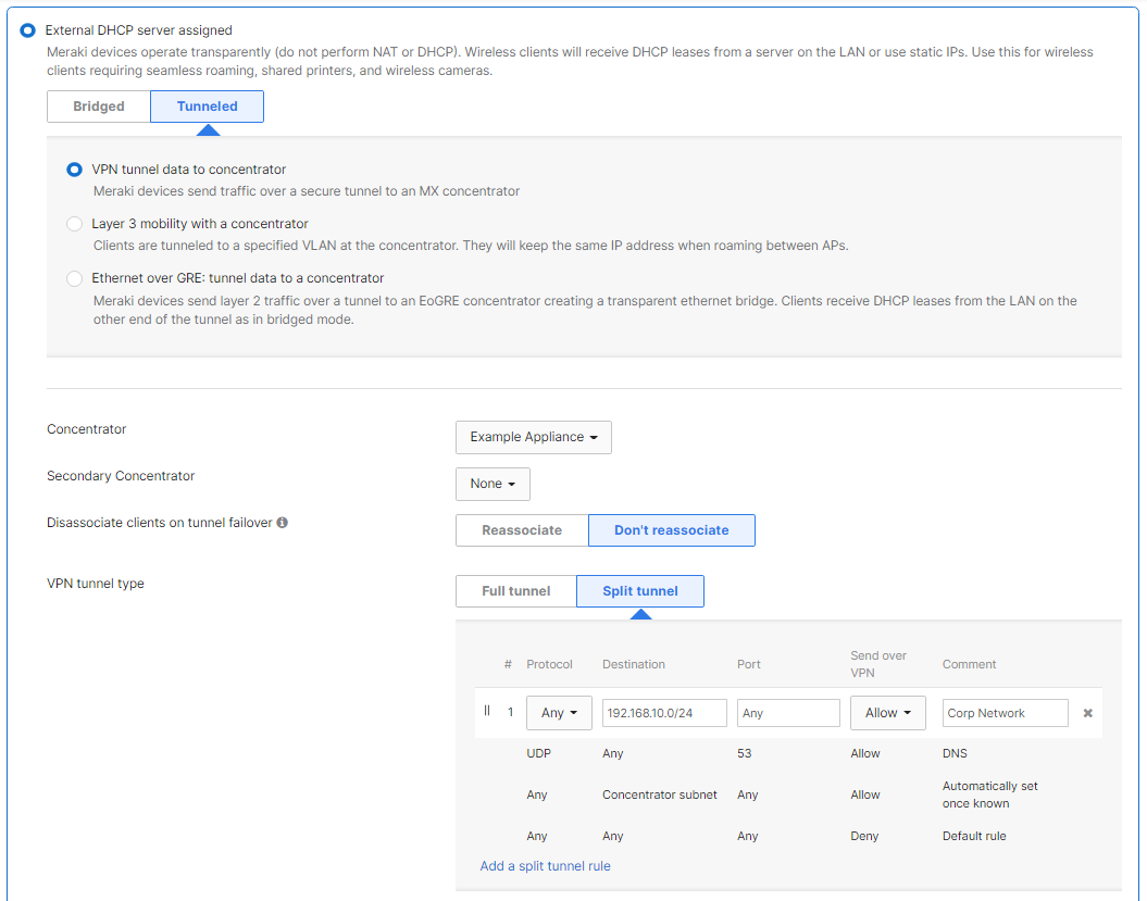
When selecting Split tunnel for the VPN tunnel type, any traffic that isn't sent over the VPN tunnel to the concentrator will be NAT'ed to the IP address of the management interface of the MR, and send out into the local LAN (via the wired interface of the MR).
EoGRE Concentration
When configuring EoGRE to tunnel data to a concentrator, unencrypted stateless layer 2 traffic is able to reach a centralized gateway.
For more information on configuring EoGRE Concentration, see EoGRE Concentration for SSIDs.
WPA2-Enterprise RADIUS Authenticator
WPA2-Enterprise uses 802.1X to secure the wireless network. There are three pieces to 802.1X authentication: a supplicant, an authenticator, and an authentication server. In other operating modes like Bridge Mode and NAT Mode, the AP assumes the role of the authenticator. SSIDs configured for VPN Concentrator and concentrated Layer 3 roaming SSIDs will pass the authenticator role to the VPN Concentrator.
If CoA on an enterprise SSID is required, this is only supported in MXs tracking clients by MAC address and in Passthrough or VPN Concentrator mode. For more information click here.
In many cases each RADIUS authenticator must be added to the RADIUS authentication server such as Microsoft NPS or Cisco ISE. For VPN concentration and concentrated Layer 3 roaming SSIDs, just concentrators would need to be added to the RADIUS authentication server.
SSID Tunneling to an MX VPN Concentrator
How SSID Tunneling Works

SSID tunneling to a concentrator should be deployed at remote sites that do not have a local MX participating in Auto VPN. This is to avoid possible "double tunnel" unexpected behavior. This behavior can be defined as client traffic traversing an MR tunnel that is also being tunneled by an MX to a VPN concentrator. This is not a recommended deployment, but the tunnel will form. Please note that there might be some MTU issues with this approach.
Expected Packet Flow

1. After an SSID is configured to tunnel traffic to an MX concentrator, both the MR and MX send Register-Request packets to Meraki VPN registries.
Note: VPN Concentrator tunneling is supported on both passthrough/concentrator mode and Routed mode MX devices.
We recommend that the MX is not configured for NAT (routed mode). If the MX is in NAT Mode, the IP packets for functions like RADIUS and WPA2-Enterprise will egress MX's WAN, irrespective of whether that interface is the most appropriate or optimal route for that traffic.
Port ranges used to contact VPN registry:
- Source: UDP port range 32768-61000
- Destination: UDP port range 9350-9381
A Register-Request message is always a packet sent from node to the VPN Registry server. Registry-Request packets do the following:
- Provides the contact information of node's source IP and UDP port the node can be reached at to form tunnels, so this information can be shared with other registered peers.
-
Request IP address of peer node's uplink and port the peer is using to form tunnels.
In an example, MR dynamically chooses UDP source port 39199 with source IP 192.168.2.3. MR then sends a Registry-Request packet to the VPN registries. The source IP gets of packet gets rewritten to the upstream NAT firewall's outside IP which is 76.126.47.131.

Similarly, the MX dynamically chooses UDP source port 49069 with source IP 192.168.10.17. The MX then sends a Registry-Request packet to the VPN registries. The source IP of the packet gets rewritten to the upstream NAT firewall's outside IP which is 128.107.241.175.

2. The VPN Registry servers reply back with Register-Response message. The Register-Response packets do the following:
- Informs the MR that the MX can be reached at IP address 128.107.241.175 and UDP port 49069.

- Informs the MX that the MR can be reached at IP address 76.126.47.131 and UDP port 39199.

3. When the MR receives connection information about the MX, it attempts to punch a hole in its local upstream firewall by sending packets to the outside IP address of the NAT firewall that the MX concentrator sits behind with the following parameters:
- Source IP: 192.168.2.3 (NATs to 76.126.47.131)
- Source Port: 39199
- Destination IP: 128.107.241.175
- Destination Port: 49069
4. When the first UDP packet sent by the MR reaches the MX, the stateful nature of upstream firewall drops it because the NAT table doesn't contain a session that allows inbound traffic from the MR firewall's outside IP.
5. When the MX receives connection information about the MR, it attempts to punch a hole in its local upstream firewall by sending packets to outside the IP address of the NAT firewall that the MR sits behind with following parameters:
- Source IP: 192.168.0.17 (NATs to 128.107.241.175)
- Source Port: 49069
- Destination IP: 76.126.47.131
- Destination Port: 39199
6. When this first UDP packet sent by the MX reaches the MR's NAT firewall, it is allowed because it matches a previously established outbound session (established in #3) in the NAT table, so it is forwarded to the MR on the LAN.
7. The MR sends a second UDP packet to the MX.
8. the MX's upstream firewall allows this packet because it matches a previously established outbound session (established in #5) in the NAT table, so it is forwarded to the MX on the LAN.
9. Now an active UDP session is created in the NAT tables of both firewalls.
MR communication with the NAT firewall IP of MX:

MX communication with the NAT firewall IP of MR:

10. Both Meraki appliances can now exchange the required UDP encapsulated IPsec packets to complete the IPsec negotiation and build a tunnel.
11. Once a tunnel is built, traffic from the concentrated SSID from the MRs will be tunneled to the MX concentrator.
Note: IPsec tunnels between peers never traverse the Cloud. The VPN registry simply acts as a broker allowing peers to exchange connection specific information. The actual IPsec tunnel is always peer-to-peer.
The above example does not consider upstream NAT firewalls doing PAT (NAT overload). If the upstream firewalls are doing PAT, source ports will change when Register-Request packets are sent out. Rewritten ports will be provided to the VPN registry and will be shared to other registered peers as such.