
SSID Modes for Client IP Assignment
The Client IP assignment section of the Wireless > Configure > Access control page controls how clients will be placed on the wired network and receive an IP address when associating.
This article describes each of the client IP assignment options available, how they impact clients, and recommended use cases.
Bridge Mode
In bridge mode, the Meraki APs act as bridges, allowing wireless clients to obtain their IP addresses from an upstream DHCP server.
Bridge mode should be enabled when any of the following is true:
- Wired and wireless clients in the network need to reach each other (e.g., a wireless laptop needs to discover the IP address of a network printer, or wired desktop needs to connect to a wireless surveillance camera)
- Layer 2 multicast and broadcast packets (e.g., ARP, Bonjour) need to propagate in a limited manner to both wired and wireless clients for device discovery, networking, etc.
- The wireless network needs to support legacy VPN clients (i.e., those that do not support NAT Traversal)
- Wired and wireless clients need to have IP addresses in the same subnet for monitoring and/or access control reasons (e.g., a web gateway in the network allows/denies internet access based on the client’s IP address)
- Wireless traffic needs to be VLAN-tagged between the Meraki AP and the upstream wired infrastructure
- If IPv6 is used on the network; see the article on IPv6 bridging for more information
The implications of enabling bridge mode are as follows:
-
An administrator cannot enable adult content filtering on the SSID; it is disabled by bridge mode using the DNS server(s) advertised by the network’s DHCP server because the feature is DNS-based
-
Multiple DHCP servers are allowed, but they must assign IP addresses to wireless clients from the same subnet; this enables the IP addresses to be routed by the LAN, to which the Meraki APs are connected
Use Cases
Bridge mode works well in most circumstances, particularly for seamless roaming, and is the simplest option to put wireless clients on the LAN. Layer 3/7 firewall rules and traffic shaping can be used to restrict client traffic before it can reach the wired network, and VLAN tagging can be used to put wireless clients on a specific subnet upstream.
Diagram
In the example below, note that the source IP address of the client traffic remains the same after transparently passing through the access point.

Additional Info
For information on how to apply VLAN tags to wireless client traffic with a bridge SSID, please refer to our VLAN Tagging on MR Access Points documentation.
NAT Mode
In NAT mode, Meraki APs run as DHCP servers to assign IP addresses to wireless clients out of a private 10.x.x.x IP address pool behind a NAT.
NAT mode should be enabled when any of the following is true:
- Wireless clients associated to the SSID only require internet access, not access to local wired or wireless resources
-
There is no DHCP server on the LAN that can assign IP addresses to wireless clients
-
There is a DHCP server on the LAN, but it does not have enough IP addresses to assign to wireless clients
The implications of enabling NAT mode are as follows:
- Devices outside of the wireless network cannot initiate a connection to a wireless client
- Wireless clients cannot use layer 2 discovery protocols to find other devices on either the wired or wireless network
- Legacy VPN clients (i.e., those that do not support NAT Traversal) may not be able to establish IPSec tunnels over the wireless network. (One workaround is to upgrade the VPN client or configure the VPN client to establish an IPSec tunnel over TCP, e.g. SSL)
- VLAN Tagging wireless traffic is not supported in NAT mode
Please note that each AP will NAT to its own management IP address. As a result, LAN flows will be interrupted when the client roams between APs.
The DHCP service for NAT mode will only hand out addresses in the 10.0.0.0/8 subnet. SSIDs in NAT mode can still be used on wired networks already using a 10.x.x.x address space, however clients on the NAT SSID may be unable to communicate with these networks.
Use Cases
NAT mode works well for providing a wireless guest network since it puts clients on a private wireless network with automatic addressing. Layer 3 firewall rules can also be used to quickly limit or block access to network resources.
Diagram
In this example, note that while the client has an address in the 10.0.0.0/8 network, the source IP is altered to the IP address of the access point upon entering the LAN.

Additional Info
For more information on NAT mode, please refer to our documentation:
Layer 3 Roaming
Layer 3 roaming is a built-in feature that allows seamless roaming even when changing to an AP that is hosted in a different VLAN. This feature doesn't require a concentrator which eliminates bottlenecks within the network, and allows the client device to retain the same IP address it received on the starting AP. The access points will create a connection from the current AP back to the starting AP if the originating VLAN is not present on the target AP. This connection then tunnels traffic back to the starting AP where the original VLAN exists. Configure distributed layer 3 roaming on the Access Control page.
The layer 3 roaming test will alert of any potential upstream network issues that may prevent the feature from establishing tunnels between access points.
Use Cases
Distributed layer 3 roaming is best for large networks with a large number of mobile clients. This mode will provide a more seamless experience for client devices, ensuring they effectively roam between access points that are in different layer 3 boundaries on the network.
Diagram
In this example, the client initially connects at point 1 where its traffic is bridged onto the network. As the client roams to points 2 and 3, and associates to new access points, those access points will first tunnel the traffic back to the initial AP, and then bridge onto the network. All tunneling is done directly between APs.

Additional Resources
Please refer to our Layer 3 roaming best practices documentation for additional information.
Layer 3 Roaming with a Concentrator
Layer 3 roaming allows a client device to maintain a consistent IP address as it roams across APs located in different VLANs. By maintaining a consistent IP address, a client can ensure uninterrupted access to latency-sensitive applications, such as VoIP.
It is possible to enable layer 3 roaming for Meraki MR access points by creating a secure mobility tunnel from each access point to a mobility concentrator, which can be either a VPN concentrator or an MX security appliance. More information on layer 3 roaming architecture is available in the Meraki Layer 3 Roaming Solution Guide.
Use Cases
Layer 3 roaming with a concentrator is most helpful for networks with a moderate number of mobile clients. This mode will provide a more seamless experience.
Diagram
In this example, the client initially connects at point 1, then roams to points 2 and 3. At each point, the client's traffic is tunneled to the concentrator then bridged onto the network.

Configuring a Mobility Concentrator
It is possible to configure an MX security appliance to act as a mobility concentrator for layer 3 roaming. Refer to the instructions regarding the MX security appliance.
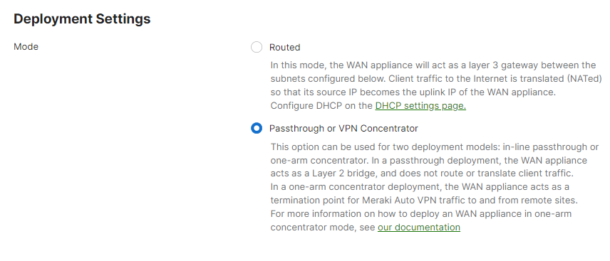
Once your mobility concentrator is online and connected to the network, be sure to place the MX or VPN concentrator in passthrough mode:
Setting the SSID to Layer 3 Roaming
After configuring a mobility concentrator, an SSID can be configured to concentrate traffic:
- Create an SSID to be used for layer 3 roaming on the Wireless > Configure > SSIDs page.
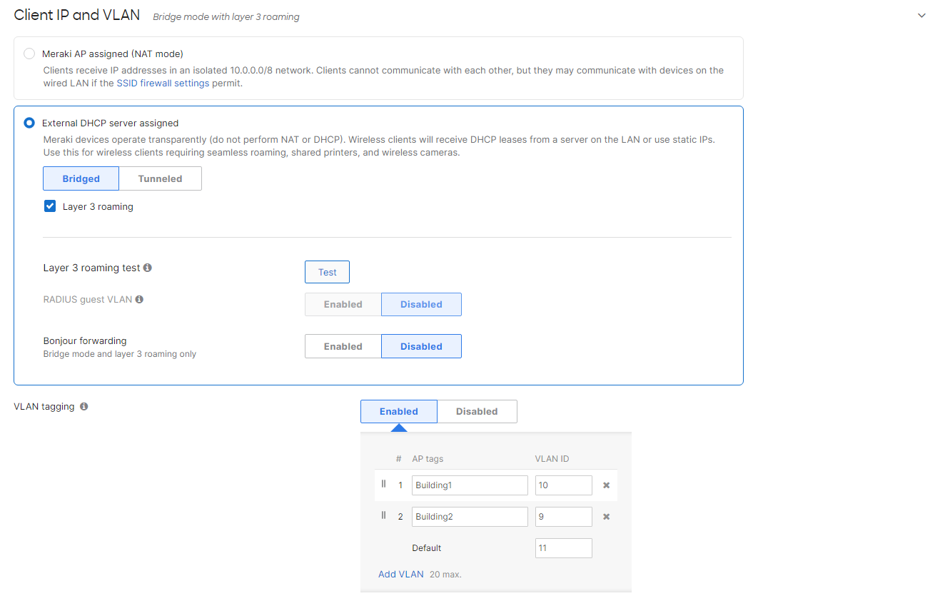
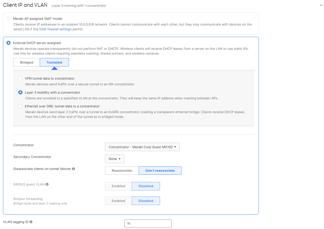
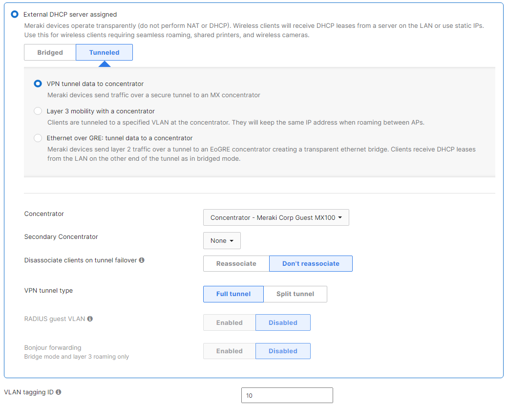
- On Wireless > Configure > Access control > Client IP and VLAN, select External DHCP server assigned and then click Tunneled.
- Select the previously created mobility concentrator in the Concentrator menu.
- Layer 3 roaming clients can optionally be tagged with a specific VLAN in the VLAN tagging ID field.
VPN - Tunnel Data to a Concentrator
Meraki Teleworker VPN enables administrators to extend the corporate LAN to employees at remote sites with Meraki APs without requiring client devices to have client VPN software installed and running. The experience of wireless clients connected to remote APs will be the same as if they were on-site at headquarters with full corporate network access.
The SSID can be configured to be in full-tunnel or split-tunnel mode depending on the targeted network design:
Use Cases
Teleworker VPN can be used to connect small branch offices, teleworker or executive home offices, temporary site offices (eg. construction sites), and traveling employees on the road back to the corporate LAN and provide access to resources back at headquarters.
Diagram
In this example, the client's traffic is passed through the secure VPN tunnel over the internet to the VPN concentrator before being bridged onto the network.
