
Transmit Power and Antenna Configuration
Learn more with these free online training courses on the Meraki Learning Hub:
Click 日本語 for Japanese
Overview
The transmit power of an AP affects the wireless coverage area and the maximum achievable signal-to-noise ratio. Proper configuration of transmit power is important for ensuring a wireless network is operating at its highest capacity. There are two methods to configure the transmit power of Meraki access points: Auto Power (Recommended) and Manual Power.
NOTE: All configuration for transmit power will be done from the Wireless > Configure > Radio Settings page.
Auto Power
Auto transmit power leverages RF data gathered by an AP to decide which radio transmit power levels would be best for client roaming and performance. More information on the Auto Power algorithm can be found in our Auto TX article. By default, all AP radios are configured to use Auto Power.
Manual Power
Each AP may alternatively be configured with a static power setting on a per-radio basis. This instructs the AP to use the manually defined power setting instead of the Auto Power algorithm. The list of power settings available is determined per-band, per-regulatory domain.
Note: There are cases where high transmit powers are available as options but mechanisms in the AP may prevent it from broadcasting at the configured power. Please see the Max Radio Power Limitations section within the RF Profiles article for more details.
Disabling or enabling a radio is considered a major configuration change, which will result in the AP reinitializing and causing brief downtime. Please keep this in mind when making this configuration change.
Configuring Manual Transmit Power
- From the Wireless > Configure > Radio Settings page, select either 2.4, 5 or 6 from the Band dropdown menu to modify the correct radio.
- Select the number/link in the Target power (dBm) column of a specific AP.
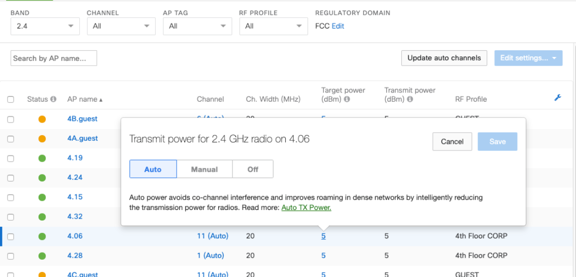
- Select Manual and choose the desired transmit power for the specified radio.
- Then select Save.
Disabling Radios
Administrators can set either the 2.4 GHz or 5 GHz radio to be turned off. This disables all client serving functions of the specified radio but does not prevent it from being used for Rogue SSID and CMX detection. Currently this function is performed individually on the respective AP's from the Radio Settings page. At this time, we can not disable AP radios using an RF profile.
- Instead of selecting Auto or Manual when the radio is being modified, select Off instead to disable client serving functions on the desired band. Example of 2.4GHz radio being disabled.
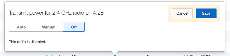
Note: Single radio models (MR12 and MR62) will appear as "Off" on the Wireless > Configure > Radio settings page under the Transmit power (dBm) column, even though the radio is not disabled. If the 2.4 GHz radio is configured to be disabled, the Transmit power (dBm) column will display "SSID disabled".
Dashboard Power and Antenna Gain
The power levels listed in dashboard are the base power levels of the AP, they do not include antenna gain.
Antenna Configuration
When using external antenna options, the Dashboard needs to have the appropriate antenna option configured in order to enforce regulatory restrictions like Equivalent Isotropically Radiated Power (EIRP). External antennas can be configured on the Wireless > Monitor > Access Points > Access Point Details page for a selected AP, at the bottom left of the page under the Config and Power sections. Select the pencil icon to edit the antenna type. Ensure the selected antenna model matches the antenna type physically installed on the AP.
WARNING: Failure to configure the correct antenna may place the AP outside of regulatory limits. The administrator is responsible for ensuring this configuration is correct.

NOTE: Dashboard populates a list of certified antennas by AP model. Refer to the MR datasheets for details on which Meraki Antennas are supported by each MR.
NOTE: As referenced in the hardware install guides, two identical antennas are necessary if using a 2-port antenna on the MR84. Other AP models may allow for different antennas per-band based on their antenna port configuration.