VRF
VRF Overview
VRF (Virtual Routing and Forwarding) lets a single router use multiple virtual routing tables. It separates different network segments, so they can use the same IP addresses without conflicts. This works without needing MPLS or complex setups.
What it does
-
Overlapping IP Addresses:
This allows different networks or customers to use the same IP address ranges without interfering with each other.
-
Isolation:
Each VRF (Virtual Routing and Forwarding) instance is isolated, meaning traffic destined for one VRF cannot reach devices in another VRF.
-
Simplifies Management:
VRF Lite can simplify network management by allowing for the logical segmentation of a network.
-
No MPLS Required:
Unlike full VRF implementations, VRF Lite does not require MPLS (Multiprotocol Label Switching) or MP-BGP (Multiprotocol Border Gateway Protocol).
-
Creates Virtual Routing Tables:
VRF Lite essentially carves up a single physical router into multiple logical routers, each with its own routing table.
How it works:
- Interfaces: Each interface on the router is assigned to a specific VRF.
- Routing Tables: Each VRF has its own routing table, independent of other VRFs.
- Forwarding: Traffic is forwarded based on the routing table associated with the VRF to which the incoming interface belongs.
Use Cases:
-
Multi-Tenant Environments:
Service providers can use VRF Lite to isolate traffic from different customers on the same physical infrastructure.
-
Network Segmentation:
VRF Lite can be used to logically separate different departments or functions within an organization.
-
Guest Networks:
It can be used to isolate guest Wi-Fi networks from the corporate network.
-
Merging Networks:
VRF Lite can help when merging networks with overlapping IP address spaces, avoiding the need for extensive re-addressing.
This feature is supported in IOS XE 17.18.1 and later on MS390 and Cloud Managed Catalyst switches.
Management traffic to Dashboard is only supported in the default VRF.

Configuring a VRF
-
Click Organization on the left menu, then click on VRFs.
-
Click Add VRF.
-
VRF Name: A friendly name for the VRF.
-
Description: A friendly name/description for the VRF.
-
Route Distinguisher: Assign a route distinguisher (RD) for the VRF that helps identify a virtual routing domain in a provider's network and allows for overlapping IP space. The route distinguisher must be a unique value on the router for each VRF.
-
Format requirements: Route distingusiher is generally expressed in the format of ASN Number:Unique number. Example: 65000:10. However, following are the format requirements. The format consists of two parts separated by a colon (:)
- First part can be one of the three formats:
- Two decimal numbers separated by a dot, each number having 1 to 10 digits (e.g., 123.456).
- A single decimal number with 1 to 10 digits (e.g., 22 or 1234567890).
- A valid IPv4 address in dotted decimal notation
- The second part after the colon is a decimal number with 1 to 10 digits (e.g., 22 or 1234567890)
- First part can be one of the three formats:
-
-
Route Target: Assign a route target (RT) to control the redistribution of routes between different VRFs. RTs identify which VRF a route belongs to, allowing for selective sharing of routes between VRFs.
-
Format requirements: Same as the requirements for Route distinguisher.
-
A maximum of 20 VRF's are supported within an Organization.
Adding Ports to a VRF
-
Click Switching on the left menu, then click on Routing & DHCP.
-
Select the interface you would like to edit and add to a pre-configured VRF.
-
In the VRF drop down box, select the VRF you would like assign the selected interface to.
- Click Save changes.

Removing Ports from a VRF
-
Click Switching on the left menu, then click on Routing & DHCP.
-
Select the interface you would like to edit and remove from a VRF.
-
In the VRF drop down box, select the default VRF to move the interface back to the default VRF.
- Click Save changes.

Deleting a VRF
You must remove all interfaces from the VRF before deleting it.
-
Click Organization on the left menu, then click on VRFs.
-
Click the VRF you would like to delete to highlight it.
-
Click Delete.

Route Leaking
Route leaking between Global Routing Table and Virtual Routing and Forwarding (VRF) table is facilitated with the use of static routes. Either method provides the next-hop IP address. At times, only a single uplink is available to peer to an upstream appliance, which in this instance, the ability to leak a route from the default routing table can be used to ensure traffic can enter/leave a VRF.
-
Click Add static routes or the pencil to edit an existing static route.
-
Click the Enabled box next to Global as depicted in the screen shot below.
-
Click Save.

Adding OSPF to a VRF
- Click Switching on the left menu, then click OSPF Routing.
- Next to VRFs, click the VRF you would like to enable OSPF routing in.
- Click Enabled.
- Enter in the Hello timer and dead timer values if different than the default.
- Click Add an area to configure the area.
- Enter the area ID, Name, and select the area Type.
- Click Switching on the left menu, then click on Routing & DHCP.
- Navigate to the interface you are adding the OSPF area to and click the pencil to edit.
- Under OSPF settings click on the drop down arrow next to Area and select the appropriate area.
- Configure the Cost if different than the default value of 1.
- Select if the interface will be Passive or not.
- Select the Network type*.
- Click Save changes.
If the interface is using a /31 subnet then the recommendation is to use OSPF network type point-to-point.
For more information regarding configuring OSPF on MS switches please refer to https://documentation.meraki.com/MS/..._OSPF_Overview

Tools
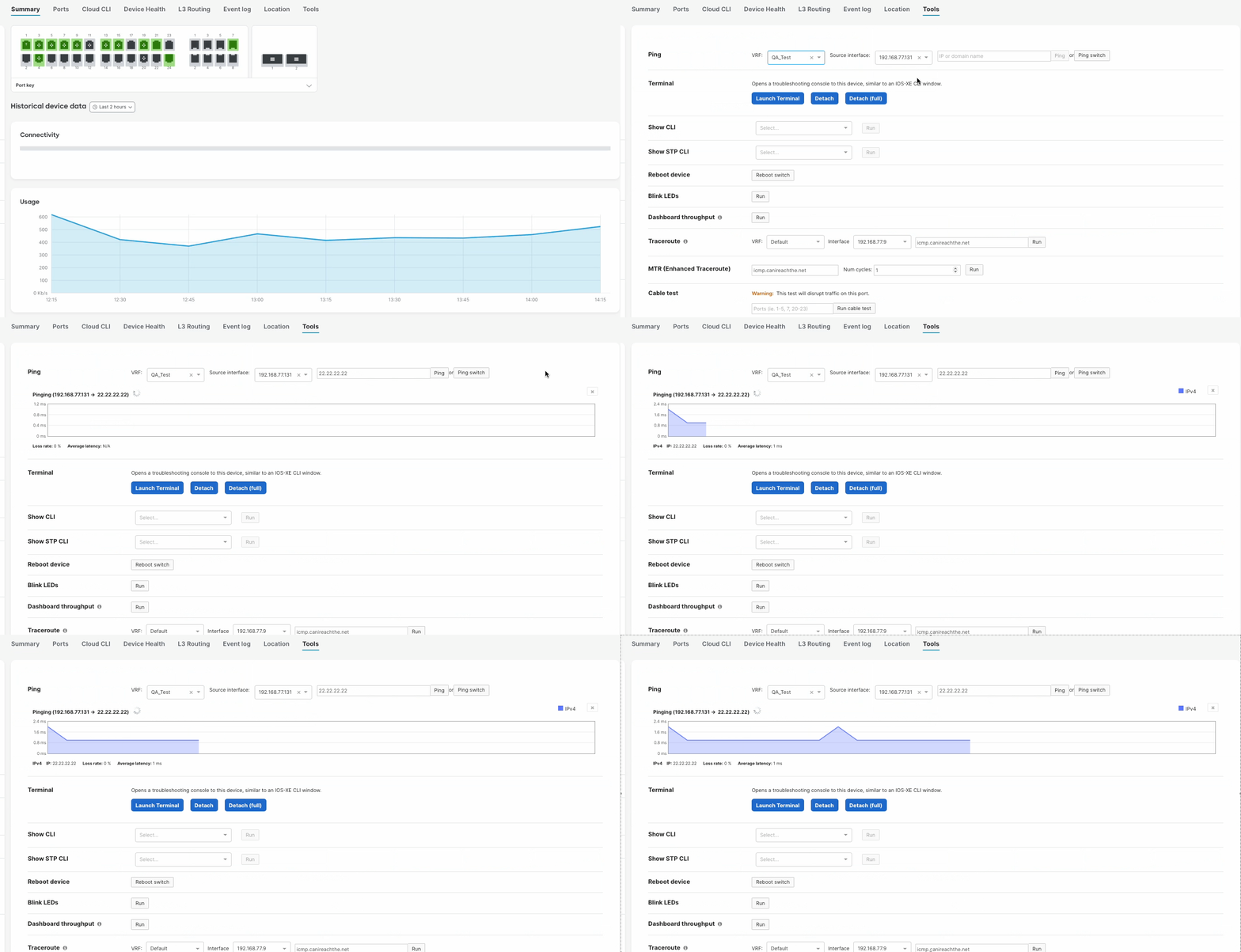
When pinging a IP address within a VRF, you must specify the VRF or else the ping will fail. Sourcing ping from a specific VRF can be done under the Switch Details, Tools page.

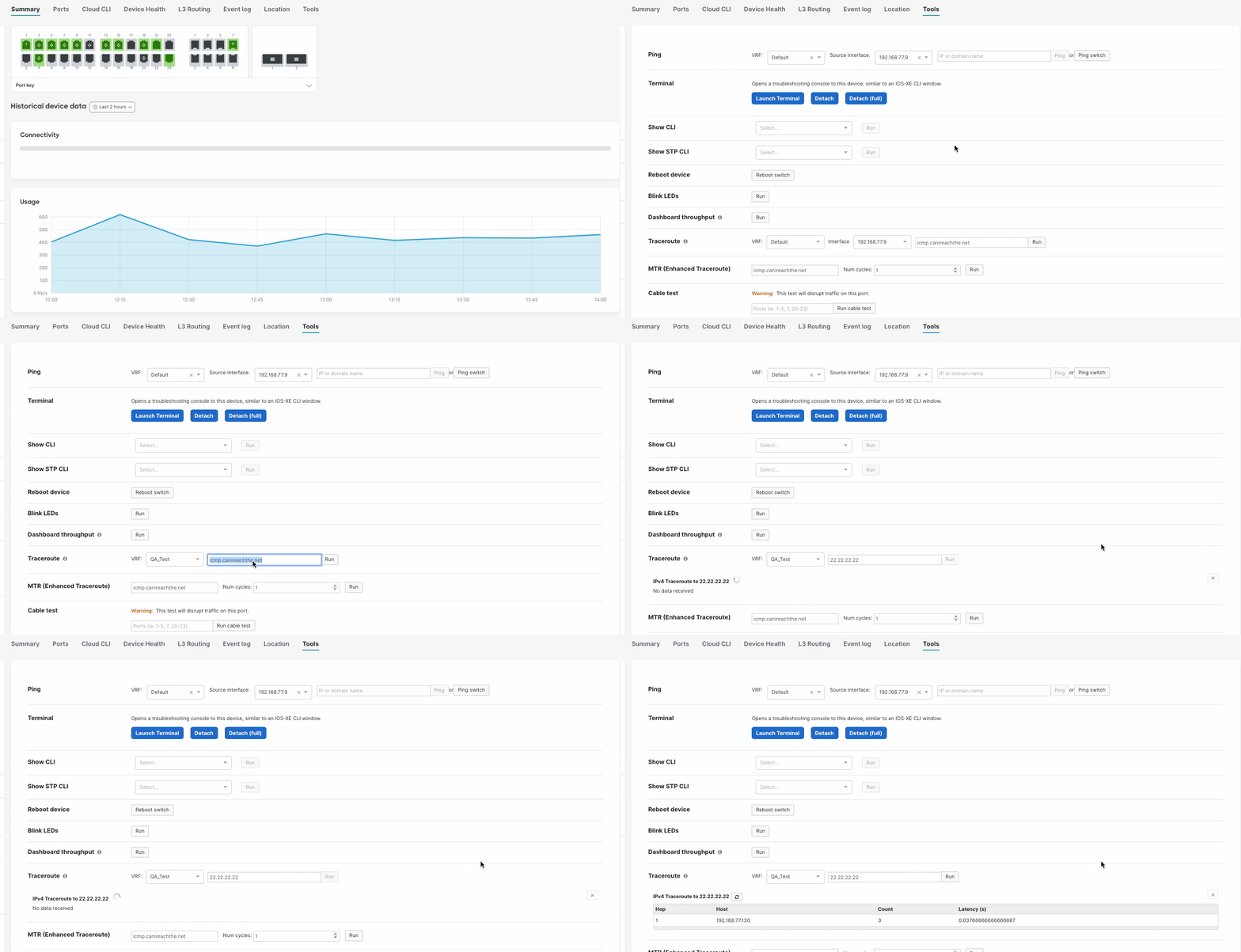
When running a traceroute to an IP address within a VRF, you must specify the VRF or else the traceroute will fail. Sourcing traceroute from a specific VRF can be done under the Switch Details, Tools page.


