
MS130 Series Installation Guide
About This Guide
This guide provides instruction on how to install and configure your MS130 series switch. This guide also provides mounting instructions and limited troubleshooting procedures. For more switch installation guides, refer to the switch installation guides section on our documentation website.
Product Overview
Physical Specifications
| MS130-8 | MS130-8P | MS130-8P-I | MS130-8X | MS130-12X | |
|---|---|---|---|---|---|
| 1Gbe RJ45 | 8 | 8 | 8 | 6 |
8 |
| mGbe RJ45 | - | - | - | 2 x 2.5G | 4 x 2.5G |
|
1 Gbe SFP |
2 | 2 | 2 | - | - |
| 10GbE SFP+ | - | - | - | 2 | 2 |
| Dedicated Mgmt Interface | - | - | - | - | - |
| PoE Type | - | 802.3bt | 802.3bt | 802.3bt | 802.3bt |
| PoE Port Budget | - | 30W | 30W | 30W | 30W |
| PoE Switch Budget | - | 120W | 120W | 120W | 240W |
| Power Input | 12VDC, 2.5A | 54VDC, 2.78A | 54VDC, 3.70A | 54VDC, 2.78A | 54VDC, 5.56A |
| Power Load (idle/max) | 8W/8W | 8W/128W | 8W/128W | 16W/136W | 19W/260W |
| Operating Temperature | 32°F - 113 °F 0°C - 45°C |
32°F - 113 °F 0°C - 45°C |
32°F - 113 °F 0°C - 45°C |
32°F - 113 °F 0°C - 45°C |
32°F - 113 °F 0°C - 45°C |
| Storage and Transportation Temperature | -4°F - 158 °F -20°C - 70°C |
-4°F - 158 °F -20°C - 70°C |
-4°F - 158 °F -20°C - 70°C |
-4°F - 158 °F -20°C - 70°C |
-4°F - 158 °F -20°C - 70°C |
| Humidity | 5% to 95% | 5% to 95% | 5% to 95% | 5% to 95% | 5% to 95% |
| Mounting |
Desktop Wall mount |
Desktop Wall mount |
Desktop Wall mount |
Desktop Wall mount |
Desktop Wall mount |
| MS130-24 | MS130-24P | MS130-24X | MS130-48 | MS130-48P | MS130-48X | |
|---|---|---|---|---|---|---|
| 1Gbe RJ45 | 24 | 24 | 18 | 48 | 48 | 40 |
| mGbe RJ45 | - | - | 6 x 2.5G | - | - | 8 x 2.5G |
| 1Gbe SFP | 4 | 4 | - | 4 | 4 | - |
| 10Gbe SFP+ | - | - | 4 | - | - | 4 |
| Dedicated Mgmt Interface | 1 | 1 | 1 | 1 | 1 | 1 |
| PoE Type | - | 802.3bt | 802.3bt | - | 802.3bt | 802.3bt |
| PoE Port Budget | - | 30W | 30W | - | 30W | 30W |
| PoE Switch Budget | - | 370W | 370W | - | 740W | 740W |
| Power Input | 100-240V~, 1.5-0.85A, 50-60Hz | 100-240V~, 8A-4A, 50-60Hz | 100-240V~, 8A-4A, 50-60Hz | 100-240V~, 1.5-0.85A, 50-60Hz | 100-240V~, 12-6A, 50-60Hz | 100-240V~, 12-6A, 50-60Hz |
| Power Load (idle/max) | 15W/15W | 32W/406W | 50W/421W | 28W/28W | 49W/803W | 60W/808W |
| Operating Temperature | 32°F - 113 °F 0°C - 45°C |
32°F - 113 °F 0°C - 45°C |
32°F - 113 °F 0°C - 45°C |
32°F - 113 °F 0°C - 45°C |
32°F - 113 °F 0°C - 45°C |
32°F - 113 °F 0°C - 45°C |
| Storage and Transportation Temperature | -4°F - 158 °F -20°C - 70°C |
-4°F - 158 °F -20°C - 70°C |
-4°F - 158 °F -20°C - 70°C |
-4°F - 158 °F -20°C - 70°C |
-4°F - 158 °F -20°C - 70°C |
-4°F - 158 °F -20°C - 70°C |
| Humidity | 5% to 95% | 5% to 95% | 5% to 95% | 5% to 95% | 5% to 95% | 5% to 95% |
| Mounting | Integrated 1U Rack Mount | Integrated 1U Rack Mount | Integrated 1U Rack Mount | Integrated 1U Rack Mount | Integrated 1U Rack Mount | Integrated 1U Rack Mount |
Product View and Physical Features
Front/Back Panels
MS130-8 front panel

MS130-8P front panel

MS130-8/8P back panel

MS130-8P-I front panel

MS130-8P-I back panel
MS130-8X front/back panels


MS130-12X front, back panels


MS130-24 front/back panels


MS130-24P front/back panel

MS130-24X front panel

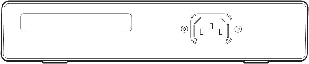
MS130-24P/24X back panel

MS130-48 front/back panels


MS130-48P front panel

MS130-48X front panel

MS130-48P/48X back panel

Factory Reset Button
There is a factory reset button on the front panel. A brief, momentary press deletes the downloaded configuration and reboots the switch, which will then download a new copy of the config. If the button is pressed and held for at least five seconds and then released, the switch will reboot and be restored to its original factory settings by deleting all configuration information stored on the unit.
Ports and Status Indicators
The MS uses LEDs to inform the user of the device's status. Functions are described below, from left to right. For fixed Ethernet ports, the status LED is on the top left or bottom right depending on port orientation. There is also a traffic LED which flashes orange as traffic is sent/received through that port.
|
Function |
LED Status |
Meaning |
|---|---|---|
|
Power |
Solid orange |
Switch is unable to connect to the Meraki cloud |
|
Flashing white |
Firmware upgrade in process |
|
|
Solid white |
Switch is fully operational and connected to the Meraki cloud |
|
|
Off |
Switch does not have power |
|
|
Switch Ports |
Off |
Port is operating at less than full speed. For example:
|
|
Solid green |
Port is operating at full speed
|
Package Contents
In addition to the MS switch, the following are provided:
-
- Rack-mount screw kit (for MS130-24, 24P. 24X, 48, 48P, 48X models)
Safety and Warnings
These operations are to be taken with respect to all local laws. Please take the following into consideration for safe operation:
- Power off the unit before you begin. Read the installation instructions before connecting the system to the power source.
- Before you work on any equipment, be aware of the hazards involved with electrical circuitry and be familiar with standard practices for preventing accidents.
- Read the mounting instructions carefully before beginning installation. Failure to use the correct hardware or to follow the correct procedures could result in a hazardous situation to people and damage to the system.
- This product relies on the building’s installation for short-circuit (overcurrent) protection. Ensure that the protective device is rated not greater than: 15 A, 125 Vac, or 10A, 240 Vac.
- Please only power the device with the provided power cables to ensure regulatory compliance.
Pre-install Preparation
You should complete the following steps before going on-site to perform an installation.
Configure Your Dashboard Network
The following is a brief overview only of the steps required to add a switch to your network. For detailed instructions about creating, configuring and managing Meraki networks, refer to the online documentation (documentation.meraki.com).
- Login to http://dashboard.meraki.com. If this is your first time, create a new account.
- Find the network to which you plan to add your switches or create a new network.
- Add your switches to your network. You will need your Meraki order number (found on your invoice) or the serial number of each switch, which looks like Qxxx-xxxx-xxxx, and is found on the bottom of the unit. You will also need your Enterprise license key, which you should have received via email.
- Go to the map / floor plan view and place each switch on the map by clicking and dragging it to the location where you plan to mount it.
Check and Set Firmware
To ensure your switch performs optimally immediately following installation, it is recommended that you facilitate a firmware upgrade prior to mounting your switch.
- Attach your switch to power and a wired Internet connection.
- The switch will turn on and the power LED will glow solid orange.
- If the unit requires an upgrade, the power LED will begin blinking white until the upgrade is complete, at which point the LED will turn solid white. You should allow at least a few minutes for the firmware upgrade to complete, depending on the speed of your internet connection.
Check and Configure Upstream Firewall Settings
If a firewall is in place, it must allow outgoing connections on particular ports to particular IP addresses. The most current list of outbound ports and IP addresses for your particular organization can be found on the firewall configuration page in your dashboard.
Assigning an IP Address
All switches must be assigned routable IP addresses. These IP addresses can be dynamically assigned via DHCP or statically assigned.
Dynamic Assignment
When using DHCP, the DHCP server should be configured to assign a static IP address for each MAC address belonging to a Meraki switch. Other features of the network, such as 802.1X authentication, may rely on the property that the switches have static IP addresses.
Static Assignment
Static IPs are assigned using the local web server on each switch. The following procedure describes how to set the static IP:
- Using a client machine (e.g., a laptop), connect to the switch over a wired connection.
- Using a web browser on the client machine, access the switch’s built-in web server by browsing to http://my.meraki.com. Alternatively, browse to http://1.1.1.100
- Click on the “Uplink Configuration” tab. Log in. The default login is the serial number (e.g. Qxxx-xxxx-xxxx), with no password (e.g., Q2DD-551C-ZYW3).
- Configure the static IP address, net mask, gateway IP address and DNS servers that this switch will use on its management connection.
- If necessary, reconnect the switch to the LAN.
Static IP via DHCP Reservations
Instead of associating to each Meraki switch individually to configure static IP addresses, an administrator can assign static IP addresses on the upstream DHCP server. Through “DHCP reservations,” IP addresses are “reserved” for the MAC addresses of the Meraki switches. Please consult the documentation for the DHCP server to configure DHCP reservations.
Installation Instructions
Each switch comes with a graphical instruction pamphlet within the box. This pamphlet contains detailed step by step guides and images to assist in the physical install of the switch.
Rack Mount
Rack mount installation instructions for the MS130-24, MS130-24P, MS130-24X, MS130-48, MS130-48P, and MS130-48X.
1. Install mounting cage nuts in the rack being used for the switch. Cage nuts need to be the correct size for the rack in question, and are not provided with the switch. They are often included with the rack. Contact the rack manufacturer for cage nut specifications.

2. Attach the switch face plate to the cage nuts on the rack, using screws appropriately sized for the cage nuts in use.

3. Connect the power cable to the switch, then apply power to the power supply unit.

8. (Optional) Install additional SFP+ units as needed, depending on the compatibility of your model.
Wall Mount
Integrated wall mount instructions for the MS130-8, MS130-8P, MS130-8P-I, MS130-8X, and MS130-12X.


Basic Troubleshooting
The following steps can be used for troubleshooting basic connectivity issues with your switch.
- Reset the switch
- Factory reset the switch by holding the factory reset button for 5 seconds
- Try switching cables, or testing your cable on another device
If your switch still does not connect, the following instructions may be useful, depending on your issue: Troubleshooting an MS Switch.
Reference https://documentation.meraki.com/MS for additional information and troubleshooting tips.
If you are still experiencing hardware issues, please contact Cisco Meraki support by logging in to dashboard and using the Help option near the top of the page, then opening and email case or calling using the contact information on that page.
Warranty
MS Warranty coverage periods are as follows:
| MS130 Series | Lifetime | - |
|---|---|---|
| MS Accessories | 1 Year |
The following are considered accessories: SFP Modules, twinax/SFP+ cables, stacking cables, all mounting kits and stands, antennas, interface modules, additional power cords, PoE injectors |
Note: The above table is a general guideline for warranty terms and is not final. Warranty terms are subject to printed warranty information on the relevant online Meraki data sheets.
If your Cisco Meraki device fails and the problem cannot be resolved by troubleshooting, contact support to address the issue. Once support determines that the device is in a failed state, they can process an RMA and send out a replacement device free of charge. In most circumstances, the RMA will include a pre-paid shipping label so the faulty equipment can be returned.
In order to initiate a hardware replacement for non-functioning hardware that is under warranty, you must have access to the original packaging the hardware was shipped in. The original hardware packaging includes device serial number and order information, and may be required for return shipping.
Meraki MS130 devices have been tested and found to comply with the limits for a Class A digital device, pursuant to part 15 of the FCC rules. These limits are designed to provide reasonable protection against harmful interference in a residential installation. This equipment generates, uses and can radiate radio frequency energy and, if not installed and used in accordance with the instructions, may cause harmful interference to radio communications. However, there is no guarantee that interference will not occur in a particular installation.
Additional warranty information can be found on: https://meraki.cisco.com/support#process:warranty
Support and Additional Information
If issues are encountered with device installation or additional help is required, contact Meraki Support by logging in to dashboard.meraki.com and opening a case by visiting the Get Help section.
For additional information on Meraki hardware and for other installation guides, please refer to documentation.meraki.com.