
MS130R Series Installation Guide
About this Guide
This guide provides instruction on how to install and configure your MS130R series switch. This guide also provides mounting instructions and limited troubleshooting procedures. For more switch installation guides, refer to the switch installation guides section on our documentation website.
Product Overview
Physical Specifications
| MS130R-8P | |
| 1Gbe RJ45 | 8 |
| 1GbE SFP | 2 |
| Dedicated Mgmt Interface | - |
| PoE Type | 802.3bt |
| PoE Port Budget | 30W |
| PoE Switch Budget | 240W |
| Power Input |
54VDC, 5.6A |
|
Power Load (idle/max) |
12W/136W |
| Power Consumption | 12W-257W |
| Operating Temperature | |
|
Storage and Transportation Temperature |
-4°F - 158 °F -20°C - 70°C |
| Humidity | 5% to 95% |
| Mounting |
Desktop, Wall mount, DIN rail options |
| Switching Capacity | 20Gbps |
| Power Supply | External AC Adapter or DIN rail AC power supply options |
| Fan Operation | |
| Dimensions (h x w x d) |
1.75 x 6.18 x 6.69in (4.4 x 15.7 x 17cm) |
| Weight | 2.12 lb (0.96 kg) |
Thermal and PoE specifications
Operating temperature limitations
| Installation Environment |
Fan/blower equipped enclosure |
Vented enclosure | Sealed enclosure | Desktop |
| Ventilation | 200 LFM | 40 LFM | 0 LFM | 40 LFM |
| Operating Temperature Limits |
-40°F - 158°F -40ºC to 70ºC |
-40°F - 149°F -40ºC to 65ºC |
-40°F - 140°F -40ºC to 60ºC |
Vertical -40ºC to 60ºC Horizontal -40ºC to 55ºC |
Airflow around the switch must be unrestricted. To prevent the switch from overheating, you must have the following minimum clearances:
- Top and bottom: 2.0 in. (50.8 mm)
- Sides: 1.0 in. (25.4 mm)
- Front: 2.0 in. (50.8 mm)
Caution: When the switch is installed in an enclosure, the temperature within the enclosure is greater than normal room temperature outside the enclosure. For example the DIN rail power supply also generates heat which may raise the temperature on the switch. To reduce this increase ventilation or space between the power supply and the switch.
Power Supply De-rating
De-rating is the reduction of the output power depending on the ambient temperatures. When the ambient temperature rises above a certain threshold, the amount of power that the power supply can output decreases as the temperature rises, which limits the amount of power the switch can provide to connected PoE devices.
| Power Supply | MA-PWR-300W-INDADP | PWR-IE240W-PCAC-L= | PWR-IE480W-PCAC-L= |
| De-rating | 24W/5°C over 45°C | 30W/5°C over 50°C | 60W/5°C over 50°C |
Product View and Physical Features
Side/Front Panels


|
A |
Power connector DC-A using external AC adapter |
|
B |
Power connector DC-A using DIN rail AC power supply |
|
C |
Protective ground connection |
|
D |
LED Status Lights |
|
E |
Reset Button |
|
F |
1GbE RJ45 Ports |
|
G |
1GbE SFP Module Slots |
 |
Caution; Hot Surface |
 |
Direct Current |
 |
Functional Earth Terminal |
Factory Reset Button
There is a factory reset button on the front panel. A brief, momentary press deletes the downloaded configuration and reboots the switch, which will then download a new copy of the config. If the button is pressed and held for at least five seconds and then released, the switch will reboot and be restored to its original factory settings by deleting all configuration information stored on the unit.
Ports and Status Indicators
The MS uses LEDs to inform the user of the device's status. Functions are described below, from left to right. For fixed Ethernet ports, the status LED is on the top left or bottom right depending on port orientation. There is also a traffic LED which flashes orange as traffic is sent/received through that port.
|
Function |
LED Status |
Meaning |
|---|---|---|
|
Power |
Solid orange |
Switch is unable to connect to the Meraki cloud |
|
Flashing white |
Firmware upgrade in process |
|
|
Solid white |
Switch is fully operational and connected to the Meraki cloud |
|
|
Off |
Switch does not have power |
|
|
Switch Ports |
Off |
Port is operating at less than full speed. For example:
|
|
Solid green |
Port is operating at full speed
|
Package Contents
In addition to the MS switch, the following are provided:
-
- 19" rack mount brackets
- Wall mount brackets
Screw kits can be purchased separately.
Safety and Warnings
These operations are to be taken with respect to all local laws. Please take the following into consideration for safe operation:
- Power off the unit before you begin. Read the installation instructions before connecting the system to the power source. Always ensure you plug the connector to the unit prior to plugging into a power source.
- Before you work on any equipment, be aware of the hazards involved with electrical circuitry and be familiar with standard practices for preventing accidents.
- Read the mounting instructions carefully before beginning installation. Failure to use the correct hardware or to follow the correct procedures could result in a hazardous situation to people and damage to the system.
- This product relies on the building’s installation for short-circuit (overcurrent) protection. Ensure that the protective device is rated not greater than: 15 A, 125 Vac, or 10A, 240 Vac.
- Please only power the device with the provided power cables to ensure regulatory compliance.
Pre-install Preparation
You should complete the following steps before going on-site to perform an installation.
Configure your Dashboard Network
The following is a brief overview only of the steps required to add a switch to your network. For detailed instructions about creating, configuring and managing Meraki networks, refer to the online documentation (documentation.meraki.com).
- Login to http://dashboard.meraki.com. If this is your first time, create a new account.
- Find the network to which you plan to add your switches or create a new network.
- Add your switches to your network. You will need your Meraki order number (found on your invoice) or the serial number of each switch, which looks like Qxxx-xxxx-xxxx, and is found on the bottom of the unit. You will also need your Enterprise license key, which you should have received via email.
- Go to the map / floor plan view and place each switch on the map by clicking and dragging it to the location where you plan to mount it.
Check and Set Firmware
To ensure your switch performs optimally immediately following installation, it is recommended that you facilitate a firmware upgrade prior to mounting your switch.
- Attach your switch to power and a wired Internet connection.
- The switch will turn on and the power LED will glow solid orange.
- If the unit requires an upgrade, the power LED will begin blinking white until the upgrade is complete, at which point the LED will turn solid white. You should allow at least a few minutes for the firmware upgrade to complete, depending on the speed of your internet connection.
Check and Configure Upstream Firewall Settings
If a firewall is in place, it must allow outgoing connections on particular ports to particular IP addresses. The most current list of outbound ports and IP addresses for your particular organization can be found on the firewall configuration page in your dashboard.
Assigning an IP Address
All switches must be assigned routable IP addresses. These IP addresses can be dynamically assigned via DHCP or statically assigned.
Dynamic Assignment
When using DHCP, the DHCP server should be configured to assign a static IP address for each MAC address belonging to a Meraki switch. Other features of the network, such as 802.1X authentication, may rely on the property that the switches have static IP addresses.
Static Assignment
Static IPs are assigned using the local web server on each switch. The following procedure describes how to set the static IP:
- Using a client machine (e.g., a laptop), connect to the switch over a wired connection.
- Using a web browser on the client machine, access the switch’s built-in web server by browsing to http://my.meraki.com. Alternatively, browse to http://1.1.1.100
- Click on the “Uplink Configuration” tab. Log in. The default login is the serial number (e.g. Qxxx-xxxx-xxxx), with no password (e.g., Q2DD-551C-ZYW3).
- Configure the static IP address, net mask, gateway IP address and DNS servers that this switch will use on its management connection.
- If necessary, reconnect the switch to the LAN.
Static IP via DHCP Reservations
Instead of associating to each Meraki switch individually to configure static IP addresses, an administrator can assign static IP addresses on the upstream DHCP server. Through “DHCP reservations,” IP addresses are “reserved” for the MAC addresses of the Meraki switches. Please consult the documentation for the DHCP server to configure DHCP reservations.
Installation Instructions
Note: Each switch comes with a graphical instruction pamphlet within the box. This pamphlet contains detailed step by step guides and images to assist in the physical install of the switch.
DIN Rail Mount
If choosing to mount the MS130R using the DIN rail mounting bracket please us the pictures below as reference.
_-_step_1.png?revision=2)
_-_step_2.png?revision=2)
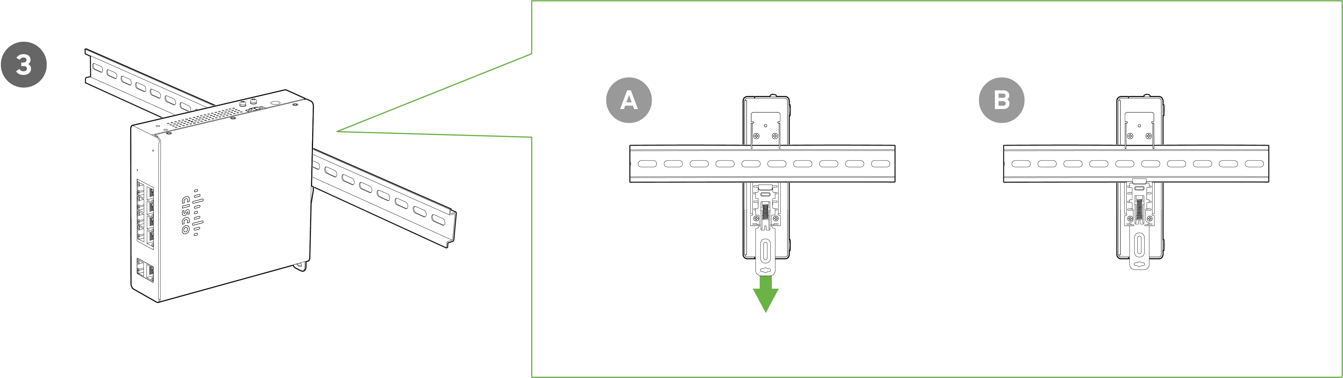_-_step_3.png?revision=2)
Wall Mount
If choosing to mount the MS130R using the wall mounting brackets please us the pictures below as reference.
_-_step_1.png?revision=2)
_-_step_2.png?revision=2)
_-_step_3.png?revision=2)
Rack Mount
If choosing to mount the MS130R using the rack mount brackets please us the pictures below as reference.
_-_step_1.png?revision=2)
_-_step_2.png?revision=2)
_-_step_3.png?revision=2)
_-_step_4.png?revision=2)
Power Options
You can use either the external AC power adapter OR the DIN rail power supply to provide power to the MS130R.

|
Caution; Hot Surface |
|
Direct Current |
|
Functional Earth Terminal |
Connecting to Power
Tools and Equipment
Obtain these necessary tools and equipment:
- Ratcheting torque flathead screwdriver that exerts up to 18 in-lb (2.03 N-m) of pressure.
- For the protective ground connector, obtain a single or pair of stu size 6 ring terminals (such as Hollingsworth part
number R3456B or equivalent).
- Crimping tool (such as Thomas & Bett part number WT4000, ERG-2001, or equivalent).
- 10-gauge copper ground wire.
- For DC power connections, use UL- and CSA-rated, style 1007 or 1569 twisted-pair copper appliance wiring
material (AWM) wire.
- Wire-stripping tools for stripping 10- and 18-gauge wires.
- A number-2 Phillips screwdriver.
- A flat-blade screwdriver.
Installing the Din Rail Power Supply
You install the power converter on a DIN rail, wall, or rack as you would a switch module.
Warning: This equipment is supplied as “open type” equipment. It must be mounted within an enclosure that is
suitably designed for those specific environmental conditions that will be present and appropriately designed to
prevent personal injury resulting from accessibility to live parts. The interior of the enclosure must be accessible
only by the use of a tool.
Grounding the Switch
Make sure to follow any grounding requirements at your site.
Warning: This equipment must be grounded. Never defeat the ground conductor or operate the equipment in the
absence of a suitably installed ground conductor. Contact the appropriate electrical inspection authority or an
electrician if you are uncertain that suitable grounding is available.
Warning: This equipment is intended to be grounded to comply with emission and immunity requirements. Ensure
that the switch functional ground lug is connected to earth ground during normal use.
Caution: To make sure that the equipment is reliably connected to earth ground, follow the grounding procedure
instructions, and use a UL-listed ring terminal lug suitable for number 10-to-12 AWG wire, such as Hollingsworth
part number R3456B or equivalent)
Caution: Use at least a 4 mm2 (0.006 in2) conductor to connect to the external grounding screw.
 All wire must be rated to at least 105°C
The ground lug is not supplied with the switch. You can use one of the these options:
- Single ring terminal
- Two single ring terminals
To ground the switch to earth ground by using the ground screw, follow these steps:
1. Use a standard Phillips screwdriver or a ratcheting torque screwdriver with a Phillips head to remove the ground
screw from the side panel of the switch. Store the ground screw for later use.
2. Use the manufacturer’s guidelines to determine the wire length to be stripped.
3. Insert the ground wire into the ring terminal lug, and using a crimping tool, crimp the terminal to the wire. If two ring terminals are being used, repeat this action for a second ring terminal.
Crimping the Ring Terminal

4. Slide the ground screw through the terminal.
5. Insert the ground screw into the functional ground screw opening on the front panel.
6. Use a ratcheting torque screwdriver to tighten the ground screws and ring terminal to the switch top panel. The
torque should not exceed 4.5 in-lb (0.51 N-m).

7. Attach the other end of the ground wire to a grounded bare metal surface, such as a ground bus, a grounded DIN
rail, or a grounded bare rack.
Connecting the Power Supply to a DC Power Source
You can also connect the power converter to a DC power source. Several power supplies can be used. Refer to
Supported Power Supplies, page 13 for the appropriate DC input ratings.
Note: Use copper conductors only, rated at a minimum temperature of 167°F (75°C).
Warning: Use twisted-pair supply wires suitable for 86°F (30°C) above surrounding ambient temperature outside
the enclosure.
1. Measure a single length of stranded copper wire long enough to connect the power converter to the earth ground.
The wire color might differ depending on the country that you are using it in.
For connections from the power converter to earth ground, use shielded 14-AWG stranded copper wire.
2. Measure a length of twisted-pair copper wire long enough to connect the power converter to the DC power source.
For DC connections from the power converter to the DC source, use 10-AWG twisted-pair copper wire.
3. Using a 14-gauge wire-stripping tool, strip the ground wire and both ends of the twisted pair wires to 0.25 inch (6.3
mm) ± 0.02 inch (0.5 mm). Do not strip more than 0.27 inch (6.8 mm) of insulation from the wires. Stripping more
than the recommended amount of wire can leave exposed wire from the power and relay connector after installation.
4. Connect one end of the stranded copper wire to a grounded bare metal surface, such as a ground bus, a grounded
DIN rail, or a grounded bare rack.
5. Insert the other end of the exposed ground wire lead into the earth-ground wire connection on the power converter
terminal block. Note that the position of the power converter may vary on different switch models.
6. Tighten the earth-ground wire connection terminal block screw.
Note: Torque to 8 in.-lb, not to exceed 10 in-lb.
Warning: An exposed wire lead from a DC-input power source can conduct harmful levels of electricity. Be sure that
no exposed portion of the DC-input power source wire extends from the power and relay connector.
7. Insert the twisted-pair wire leads into the terminal block line and neutral connections. Insert the wire
lead into the neutral wire connection and the wire lead into the line wire connection. Ensure that only wire with insulation extends from the connectors.
8. Tighten the line and neutral terminal block screws.
Note: Torque to 8 in.-lb, not to exceed 10 in-lb.
9. Connect the red wire to the positive pole of the DC power source, and connect the black wire to the return pole.
Ensure that each pole has a current-limiting-type fuse rated to 30 Amp.
Wiring the DC Power Source
Read these cautions and warnings before wiring the switch to the DC power source.
Warning: A readily accessible two-poled disconnect device must be incorporated in the fixed wiring.
Warning: This product relies on the building’s installation for short-circuit (overcurrent) protection. Ensure that the
protective device is rated not greater than: 6A.
Warning: Installation of the equipment must comply with local and national electrical codes.
Warning: Before performing any of the following procedures, ensure that power is removed from the DC circuit.
Warning: Only trained and qualified personnel should be allowed to install, replace, or service this equipment.
Caution: For wire connections to the power and alarm connectors, you must use UL- and CSA-rated, style 1007 or
1569 twisted-pair copper appliance wiring material (AWM) wire (such as Belden part number 9318).
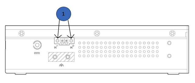
To wire the switch to a DC power source, follow these steps:
1. Locate the two power connectors on the switch front panel labeled DC-A and DC-B.
2. Identify the connector positive and return DC power connections. The labels for power connectors DC-A and DC-B
are on the switch panel as displayed below.
Label Connection
+ Positive DC power connection
– Return DC power connection
3. Measure two strands of twisted-pair copper wire (16-to-18 AWG) long enough to connect to the DC power source.
4. Using an 18-gauge wire-stripping tool, strip each of the two twisted pair wires coming from each DC-input power
source to 0.25 inch (6.3 mm) ± 0.02 inch (0.5 mm). Do not strip more than 0.27 inch (6.8 mm) of insulation from the
wire. Stripping more than the recommended amount of wire can leave exposed wire from the power connector after
installation.
Stripping the Power Connection Wire

5. Remove the two captive screws that attach the power connector to the switch, and remove the power connector.
Remove both connectors if you are connecting to two power sources.

6. On the power connector, insert the exposed part of the positive wire into the connection labeled “+” and the exposed
part of the return wire into the connection labeled “–”. Make sure that you cannot see any wire lead. Only wire with
insulation should extend from the connector.
Warning: An exposed wire lead from a DC-input power source can conduct harmful levels of electricity. Be sure that
no exposed portion of the DC-input power source wire extends from the connector(s) or terminal block(s).
7. Use a ratcheting torque flathead screwdriver to torque the power connector captive screws (above the installed wire
leads) to 2in-lb (0.226 Nm).
Caution: Do not over-torque the power connector’s captive screws. The torque should not exceed 2in-lb (0.226
Nm).
8. Connect the other end of the positive wire to the positive terminal on the DC power source, and connect the other
end of the return wire to the return terminal on the DC power source.
Attaching the Power Connectors to the Switch
To attach the power connectors to the front panel of the switch, follow these steps:
1. Insert one power connector into the DC-A receptacle on the switch front panel, and the other into the DC-B
receptacle.
Warning: Installation of the equipment must comply with local and national electrical codes.
2. Use a ratcheting torque flathead screwdriver to tighten the captive screws on the sides of the power connectors to
1.6 in/lbs.
Caution: Do not exceed 1.6 In/lbs.
.png?revision=2)

When you are installing the switch, secure the wires coming from the power connector so that they cannot be disturbed
by casual contact. For example, use tie wraps to secure the wires to the rack.
All wire must be rated to at least 105°C
Applying Power to the Power Converter
Move the circuit breaker for the AC outlet or the DC control circuit to the on position.
The LED on the power converter front panel is green when the unit is operating normally. The LED is off when the unit is
not powered or is not operating normally. After the power is connected, the switch automatically begins the power-on
self- test (POST), a series of tests that verifies that the switch functions properly.
Optional: Install additional SFP+ units as needed, depending on the compatibility of your model.
Basic Troubleshooting
The following steps can be used for troubleshooting basic connectivity issues with your switch.
- Reset the switch
- Factory reset the switch by holding the factory reset button for 5 seconds
- Try switching cables, or testing your cable on another device
If your switch still does not connect, the following instructions may be useful, depending on your issue: Troubleshooting an MS Switch.
Reference https://documentation.meraki.com/MS for additional information and troubleshooting tips.
If you are still experiencing hardware issues, please contact Cisco Meraki support by logging in to dashboard and using the Help option near the top of the page, then opening and email case or calling using the contact information on that page.
Warranty
MS Warranty coverage periods are as follows:
| MS130R Series | Lifetime | - |
| MS Accessories | 1 Year |
The following are considered accessories: SFP Modules, twinax/SFP+ cables, stacking cables, all mounting kits and stands, antennas, interface modules, additional power cords, PoE injectors |
Note: The above table is a general guideline for warranty terms and is not final. Warranty terms are subject to printed warranty information on the relevant online Meraki data sheets.
If your Cisco Meraki device fails and the problem cannot be resolved by troubleshooting, contact support to address the issue. Once support determines that the device is in a failed state, they can process an RMA and send out a replacement device free of charge. In most circumstances, the RMA will include a pre-paid shipping label so the faulty equipment can be returned.
In order to initiate a hardware replacement for non-functioning hardware that is under warranty, you must have access to the original packaging the hardware was shipped in. The original hardware packaging includes device serial number and order information, and may be required for return shipping.
Meraki MS130R devices have been tested and found to comply with the limits for a Class A digital device, pursuant to part 15 of the FCC rules. These limits are designed to provide reasonable protection against harmful interference in a residential installation. This equipment generates, uses and can radiate radio frequency energy and, if not installed and used in accordance with the instructions, may cause harmful interference to radio communications. However, there is no guarantee that interference will not occur in a particular installation.
Additional warranty information can be found on: https://meraki.cisco.com/support#process:warranty
Support and Additional Information
If issues are encountered with device installation or additional help is required, contact Meraki Support by logging in to dashboard.meraki.com and opening a case by visiting the Get Help section.
For additional information on Meraki hardware and for other installation guides, please refer to documentation.meraki.com.