StackPower
Overview
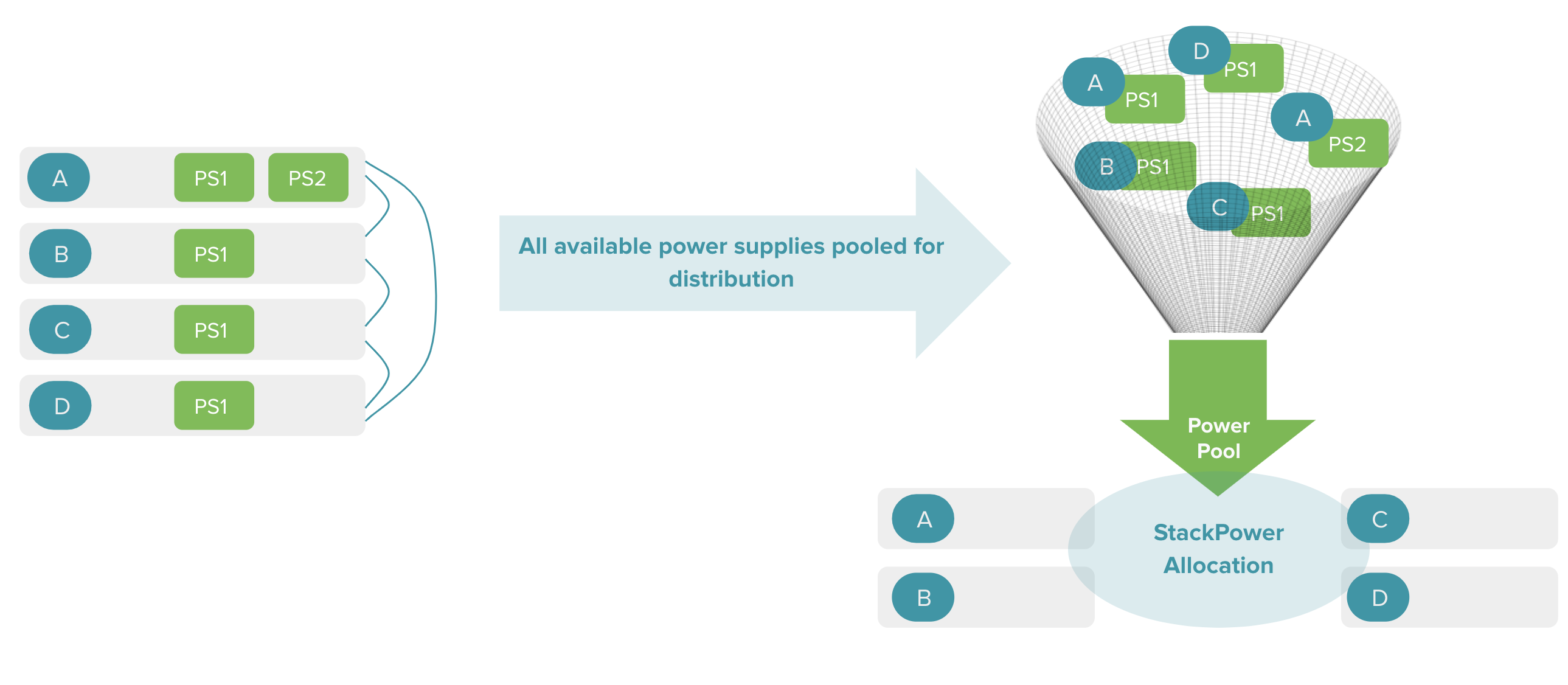
StackPower is an innovative feature that aggregates all the available power in a stack of switches and manages it as one common power pool for the entire stack.
StackPower pools and distributes power across switches using StackPower cables, providing simple and resilient power distribution throughout the stack. The back panel of the MS390 below shows the location of the StackPower ports.

Stackpower is supported by the following switches, on firmware MS 15 or IOS-XE 17.15 and later.
- MS390, C9300 and C9300-M
- C9300X and C9300X-M
- C9300S and C9300S-M
Use Case
The benefits of the StackPower technology are immediately tangible, and so are the savings. Consider a stack of switches, with each switch requiring a slightly higher power budget for some extra Power over Ethernet (PoE) devices randomly scattered in the stack. Purchasing an extra second power supply for each switch that needs additional power would be inefficient and expensive.
With the StackPower solution, a common pool of power is made available, and additional power can automatically be redirected to the appropriate switch based on the available power budget in the common power pool.

Feature Specification
StackPower technology is deployed in a ring topology and is in the power-sharing mode for the supported switches.
In power-sharing mode (the default), all input power is available to be used for power loads. The total available power in all switches in the power-stack (up to 4) is treated as a single large power supply, with power available to all switches and to all powered devices connected to PoE ports.
A maximum of 4 switches can take part in power-stack at any given time. A data-stack can have up to 8 switches, so there may be more than one StackPower power-stack in a data-stack.
Configuration
StackPower feature is enabled by default for power-sharing out of the box and requires no additional configuration on the dashboard for the supported switches.
Install the StackPower cabling correctly. Refer to the StackPower Cabling Installation guide for details.
Useful Terminologies
- Input power – the aggregate of all of the Input Power supplies.
- Allocated power – the aggregate of the all power that could be consumed by all of the circuitry (Switches, StackPower, and PoE). Note that this does not include the Reserved Power.
- Consumed power – the power that is actually being drawn from all of the combined circuitry.
- Reserved power – all of the power reserved for functions other than Switches, Infrastructure, and PoE – which is to say the Overhead Power and the Redundant Power.
- Overhead power – the power allocated for StackPower overhead – one time per power-stack (30 W).
StackPower Monitoring
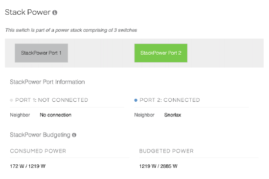
You can monitor the StackPower status and StackPower budgeting information under of the Power tab of the respective switch details page. Below is a screenshot of the StackPower section under the Power tab and the details this section provides.

StackPower Information
This section provides information about the status of the StackPower and the StackPower Ports
-
StackPower status
-
This section provides information about whether the respective switch is part of a StackPower or not and the total count of switches currently in the StackPower.
-
-
StackPower Port Information
-
This section provides information about the StackPower port status (Connected, Not Connected or Error State) and the corresponding StackPower neighbors on each of those ports (StackPower neighbor switch name and link to the corresponding switch).
-
StackPower Budgeting
Budgeting is integral to the operation of StackPower. Budgeting is required to maintain a balance between the available input power and the various loads.
This section provides budgeting information for the respective switch in comparison to the total StackPower budget.
-
Budgeted Power
-
Budgeted/ Total Input Power = An aggregate of allocated and reserved power to the respective switch from a total of all the Input powers in the StackPower.
-
-
Consumed Power
-
Consumed/ Total Budgeted Power = An aggregate of both the consumed system power and consumed PoE power for the respective switch from a total of the Budgeted power to the switch
-
Troubleshooting
Common Troubleshooting Steps
-
If you intend to use StackPower feature but are either not seeing the StackPower section under Power tab or are not seeing the StackPower port as connected, please ensure StackPower cabling is installed properly. Refer to the StackPower Cabling Installation guide for reference.
-
If the StackPower cabling is installed as suggested and you still don't see the StackPower section under Power tab reflect the correct status please reach out to Cisco Meraki Support for further troubleshooting.
FAQ
What if there are more than 4 switches in a data stack and I also want them to be in a StackPower setup ?
StackPower can only support a maximum of 4 switches in a power-stack. Hence you will have to split the data-stack into more than one StackPower setup.
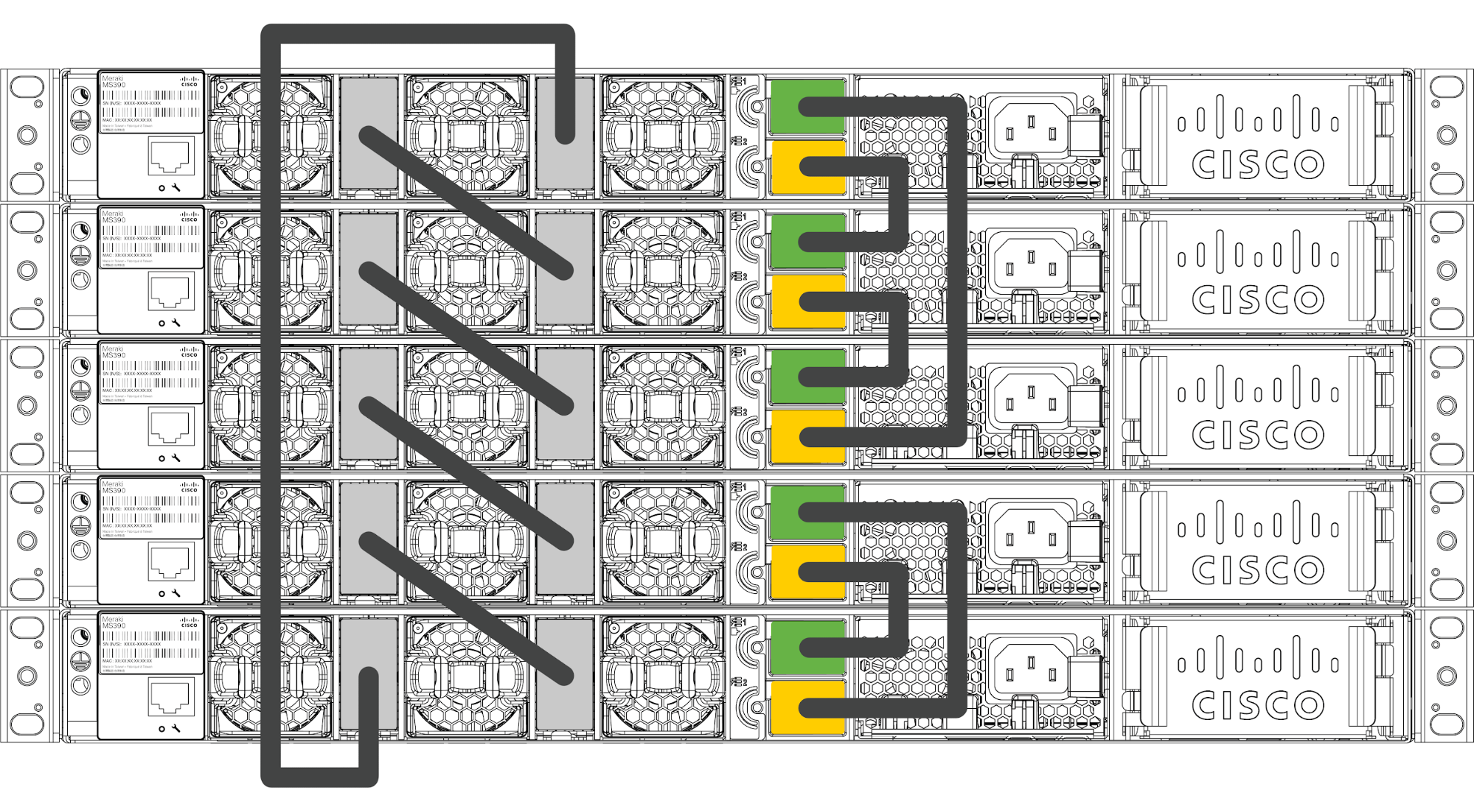
For instance, if you have a total of 5 MS switches in a data-stack, you can configure 3 switches in one power-stack setup and the rest 2 switches in another power-stack setup as shown below.
I do not intend to use StackPower feature, can I disable it?
There is no option on the dashboard to disable the StackPower feature. However, if you do not intend the switches to use the StackPower feature, please make sure to keep the StackPower cables disconnected from the StackPower ports on the switches.


