
Switch Stacks
Cloud managed switching supports several types of switch stacking on select switch models. Switch stacking allows several switches to be managed as a single, larger switch which can forward traffic over dedicated stack links rather than front-side network links. In some cases, power redundancy options are available for stacks to survive power supply failures as well.
Learn more with this free online training course on the Meraki Learning Hub:
Switch stack management IP addressing
For MS model switches, such as the MS150 series, each switch in a switch stack requires it's own management IP address. This means that a stack of 8 MS switches require 8 IP management addresses. The only exception to this requirement is the MS390 (see below).
For Catalyst model switches, such as C9300, C9200 series switches, and MS390, the switch stack uses one single management IP address. This means that a stack of 8 Catalyst switches only requires a single management IP address.
Determining How to Stack
Stacking to Fit Your Network
Meraki switches have multiple options to best fit your network deployment. This article discusses the switch stacking features that can be leveraged to best suit your deployment, specifically: Physical Stacking, and Flexible Stacking.
Understanding Physical Stacking
Physical Stacking helps provide easy management and physical redundancy. Utilizing two physical stacking ports on the back of each switch, a stack can provide for gateway redundancy at Layer 3 and dual-homing redundancy at Layer 2. Only a single uplink is required to provide connectivity to the stack once all stacking cables are installed.
For step-by-step instructions, refer to the section of this article titled Configuring a Physical Switch Stack.
When a new switch stack is created, or a new switch is added to an existing stack, the below configurations will be removed from the stand-alone switch(es) and will need to be reconfigured on the stack:
- Link aggregates
- Mirrored switch ports
- Switched virtual interface (SVIs)
- Internet Group Management Protocol (IGMP) snooping (if switch-specific settings are configured)
- Spanning-Tree Protocol (STP) priority (if switch-specific settings are configured)
Features like the ones above run one instance for the entire switch. When a stack is created, you are combining multiple physical switches all running their own instances of the feature to a single logical switch, which is why some features need to be reconfigured.
Understanding StackWise Virtual
StackWise Virtual is a Cisco technology that combines two physical switches into a single logical switch for simplified management, high availability, and scalability. It uses a high-speed StackWise Virtual Link (SVL) to synchronize the switches, providing redundancy, increased bandwidth, and seamless failover for campus core and distribution networks.
StackWise Virtual uses two interfaces
In Cisco StackWise Virtual, the StackWise Virtual Link (SVL) is used to connect two physical switches to operate as a single logical switch. The SVL synchronizes control plane information, forwards data packets, and ensures redundancy between the two switches for seamless failover and high availability.
The Dual-Active Detection (DAD) interface in Cisco StackWise Virtual is used to detect and mitigate a dual-active scenario, where both switches in the virtual stack accidentally operate as active devices due to a StackWise Virtual Link (SVL) failure.
StackWise Virtual is only available on Cloud-managed C9500 high-performance models (C9500-24Y4C, C9500-48Y4C, C9500-32QC, C9500-32C).
Understanding Flexible Stacking
Availability and redundancy are most helpful at the distribution layer of a network. On MS420 and MS425 series switches, any two switch ports can be configured as stack ports. This allows for full redundancy setup for your gateway and minimizes the impact of a failure in the network.
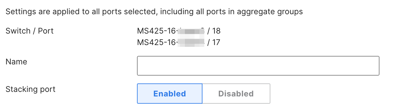
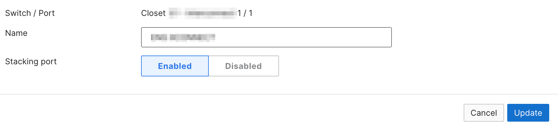
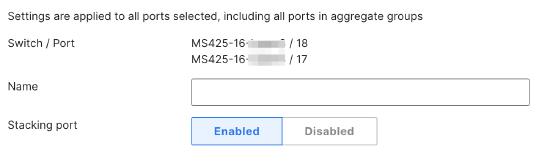
To achieve flexible stacking, go to Switching > Monitor > Switch Ports. Check two switch ports from each eligible switch in the list. Select the Edit button > Stacking port > Enabled. Use the Name field to identify the stack ports as needed.
For step-by-step instructions, refer to the section of this article titled Configuring a Flexible Switch Stack.
Understanding how the Active Stack Member is Elected
- If all stack members are powered up around the same time, the MS with the lowest MAC address will be elected the active switch.
- If the stack members are not powered up around the same time, the MS with the highest uptime will be elected the active switch, regardless of its MAC address.
- The Active switch will remain the Active switch until it has either rebooted or an event occurs that forces another active switch election (such as stack ports being reconnected).
Stacking Availability
Unless specifically noted, only like-models, regardless of switch port density, can be stacked. For example, MS350-48 and MS350-24X can be stacked, but MS250-48 cannot be stacked with an MS350-48. The exception to this rule is for the C9300X which is backward compatible and will stack with C9300 series switches.
| Model | Physical Stacking | Flexible Stacking |
|---|---|---|
| MS120 | No | No |
| MS125 | No | No |
| MS130 | No | No |
| MS150 | Yes | No |
| MS210 |
Yes (Compatible with MS225) |
No |
| MS220 |
No |
No |
| MS225 |
Yes (Compatible with MS210) |
No |
| MS250 |
Yes |
No |
| MS320 |
No |
No |
| MS350 |
Yes |
No |
| MS355 | Yes | No |
| MS390 | Yes | No |
| C9300-M | Yes, Data + Power | No |
| C9300X-M | Yes, Data + Power | No |
| C9300L-M | Yes*, Data Only | No |
| MS410 |
Yes |
No |
| MS420 |
No |
Yes |
| MS425 |
No |
Yes |
| MS450 |
Yes |
No |
*Note: Stacking the 9300L requires a stacking kit, it is not included by default. Please order a C9300L-STAK-KIT2-M with every C9300L that you plan on stacking. The stack kit includes two stacking ports and a stack cable
For switches that support Physical/Flexible Stacking:
| Stacking Cable Data Rate | Compatible Series |
|---|---|
|
40 Gigabit |
|
|
100 Gigabit |
|
| 320 Gigabit |
|
|
480 Gigabit / 1 Terabit |
|
For full information about stacking cable compatibility, available options, and product IDs, see the Stacking Cables section of the SFP and Stacking Accessories datasheet.
Configuring a Physical Switch Stack
Up to eight switches can be configured in a physical stack to allow for high-speed communication between devices.
Only like-models can be stacked. For example, MS350-48 and MS350-24X can be stacked, but MS250-48 cannot be stacked with a MS350-48. The only exception is that MS210 and MS225 models can be members of the same stack.
Physical stacking is available on MS150, MS210, MS225, MS250, MS350, MS355, MS390, C9300/L/X, MS410, and MS450 switches, which include dedicated stacking ports. This section describes physical stacking.
Flexible stacking is available on MS420 and MS425 switches which do not have dedicated stacking ports; any switch port on these switches can be configured as a stack port. For flexible stacking, check the Configuring a Flexible Switch Stack section of this article.
Physical Switch Stack Configuration Steps
The steps below explain how to prepare a group of switches for physical stacking, how to stack them together, and how to configure the stack in dashboard. Refer to the Meraki Physical Switch Stacking Configuration video.
- Add the switches into a dashboard network. For that, follow the Adding and Removing Devices from Dashboard Networks article. This can be a new dashboard network for these switches, or an existing network with other switches. Do not configure the stack in dashboard yet.
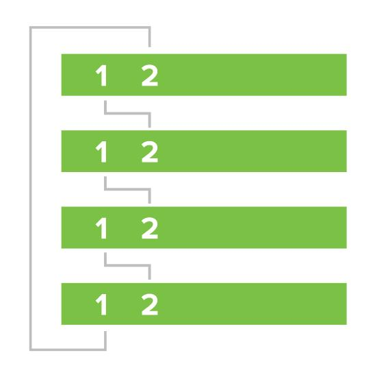
- With all switches powered off and links disconnected, connect the switches together via stacking cables in a ring topology (as shown in the following image). To create a full ring, start by connecting switch 1/stack port 1 to switch 2/stack port 2, then switch 2/stack port 1 to switch 3/stack port 2 and so forth, with the bottom switch connecting to the top switch to complete the ring.

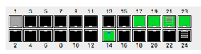
- Make sure that the stacking cables are connected correctly. If there are LED lights for the stack cables, it should turn orange when a cable is detected and green when the stack status is good:
- Correct orientation - The black tab on the cable heads should face up

- Incorrect orientation - The black tab on the cable heads are facing down

- Correct orientation - The black tab on the cable heads should face up
- Make sure that the stacking cables are connected correctly. If there are LED lights for the stack cables, it should turn orange when a cable is detected and green when the stack status is good:
- Connect one cable to act as a single uplink from 1 switch of the stack. Power on all the switches, then wait several minutes for them to download the latest firmware and updates from dashboard. The switches may reboot during this process.
- The power LEDs on the front of each switch will blink during this process.
- Once the switches are done downloading and installing the firmware, their power LEDs will stay solid white or green.
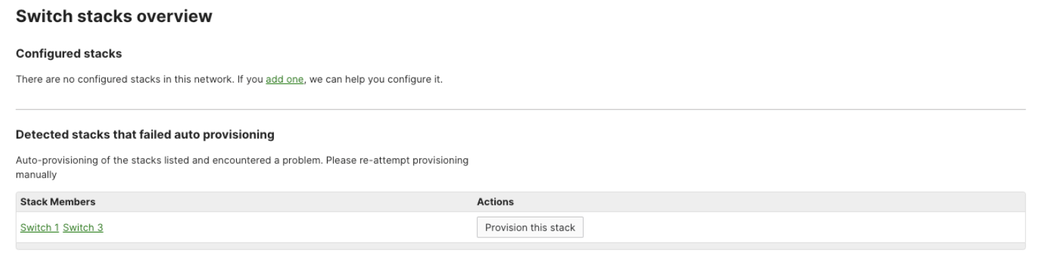
- The dashboard will now automatically attempt to provision detected potential stacks for you. This has the same effect as clicking the "Provision this stack" button, and the dashboard will only attempt this once. If the dashboard is unable to auto-provision the stack, the switches will appear on the same page in the Detected stacks that failed auto provisioning section, and the stack will need to be manually provisioned using the Provision this stack button once the cause of the provisioning failure has been fixed.
When rebooting a stack member from the dashboard using the "Reboot device" tool will reboot only that individual stack member. The same applies when performing a factory reset on a stack member. This does not apply to MS390 or C9300/L/X stacked switches, for the behavior of these models please refer to the section Stacking Catalyst Switches
Creating a stack manually
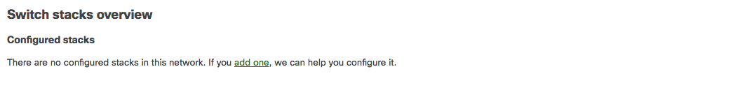
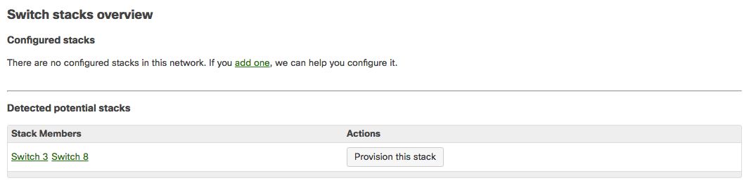
If the dashboard does not detect the potential stack, you can configure the stack manually. Navigate to Switching > Monitor > Switch stacks. Click the link to add one or the Add a stack button, depending on the option available:
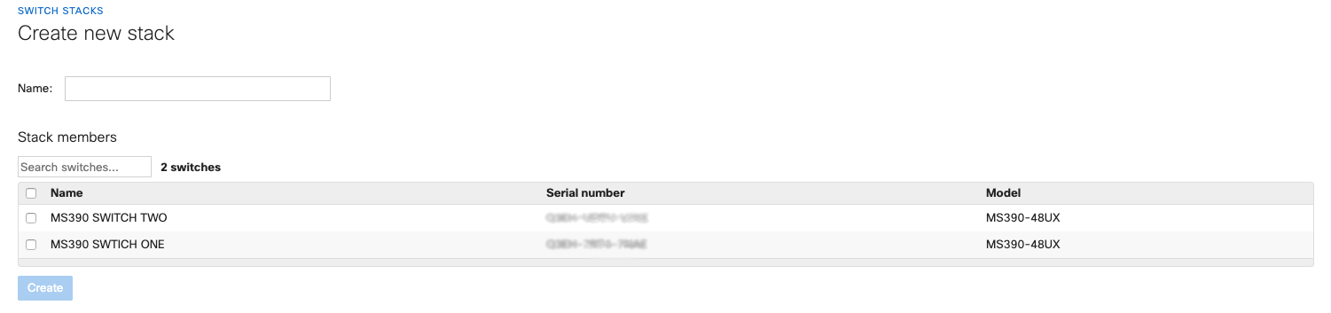
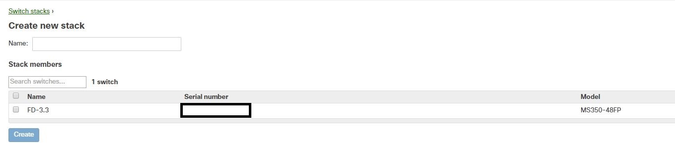
Next, select the checkboxes of the switches you would like to stack, enter a name for the stack, and click Create.

Validate the switches are now successfully stacked via Switching > Monitor > Switch stacks
6. If unsuccessful, review and correct the error and reattempt provisioning.
NOTE: After the switch stack is up and running, multiple uplinks can be added for redundancy.
Stacking Catalyst Switches
Follow the steps below to setup a Catalyst switch stack or watch the Cisco Meraki MS390 Stack Setup Walkthrough video.
- Add the switches into a dashboard network. For that, you may follow Adding and Removing Devices from Dashboard Networks article. This can be a new dashboard network for these switches, or an existing network with other switches. Do not configure the stack in dashboard yet.
- With all switches powered off and links disconnected, connect the switches together via stacking cables in a ring topology (as shown in the following image). To create a full ring, start by connecting switch 1/stack port 1 to switch 2/stack port 2, then switch 2/stack port 1 to switch 3/stack port 2 and so forth, with the bottom switch connecting to the top switch to complete the ring. While connecting the stacking cables, ensure that each connector is correctly aligned to the switch's stacking port it is connecting to and finger-tighten the screws (clockwise direction). Make sure the Cisco logo is on the top side of the connector.
-
Connect one uplink to a single switch in the stack, then power on only that switch. Wait until the switch connects to Dashboard and upgrade to desired network version is completed. Power on the remaining switches, then wait several minutes for them to download the latest firmware and updates from dashboard. The switches may reboot during this process.
-
Download the same firmware build using the Firmware Upgrade Manager under Organization > Monitor > Firmware upgrades, if they are not already set for this. This helps ensure each switch is running the same firmware build. Please note that it might take close to an hour for the switches to upgrade.
-
Navigate to Switching > Monitor > Switch stacks
-
Configure the switch stack in dashboard. If dashboard has already detected the correct stack under Detected potential stacks, click Provision this stack to automatically configure the stack. Otherwise, click the link to add one or the Add a stack button, depending on the option available:
It is expected that not all member switches will appear online until the stack is fully configured in the dashboard, as instructed in step 6.
Based on the number of members in a stack, the switch stack may require approximately one hour to become operational and connect to the Meraki Dashboard.
By default the switch members are sorted alphanumerically from top to bottom on the switch stack page; this can be changed by updating the names of the relevant stack members.
The MS AutoStacking process applies to Catalyst switches as well, please see the note above regarding auto-provisioning.
- Select the checkboxes of the switches you would like to stack, name the stack, and then click Create.
7. Ensure that all switches have downloaded the latest configuration. To verify this, navigate to Switching > Monitor > Switches and select the MS390 switch. Look for CONFIG in the column on the left of the switch details page and check if the status reads Up to date.
-
When using static IP addressing for switch management interfaces rather than DHCP, the management IP address cannot be individually altered for each stack member through the dashboard. Once the stack is configured, all members will display the management IP address of the active (primary/master) switch, where the control plane resides. It is important to note that if a change to the management IP is made after the stack has been configured, that change will apply to the active switch and will be reflected across all stack members. The management IP is shared and not unique to each switch within the stack.
Note: Due to the management IP behavior described above, accessing the Local Status Page from any member will direct to the local status page of the active switch, regardless of which stack member you are physically connected to. -
Based on the number of members in a stack and switch ports being used boot time can vary.
-
Rebooting a stack member from the dashboard using the "Reboot device" tool will reboot only that individual stack member. The same applies when performing a factory reset on a stack member. (This does not apply to MS390's or Catalyst switches, which will reboot the entire stack).
-
Physically power cycling switch stack members may cause other stack members to be unreachable for a short time, while the management plane re-initializes.
Note: If an active member fails, Catalyst switches on CS firmware may briefly pause traffic to reinitialize the Meraki management container on the new active member.
Adding a new member to the stack
- Add the new switch into a dashboard network of the existing switch stack. For that, you may follow Adding and Removing Devices from Dashboard Networks article.
- Connect the new switch to an uplink to bring it online and ensure it checks in with the Meraki Dashboard.
-
Upgrade the switch to the same firmware build as that running on the switch stack, using the Firmware Upgrade Manager under Organization > Monitor > Firmware upgrades,
-
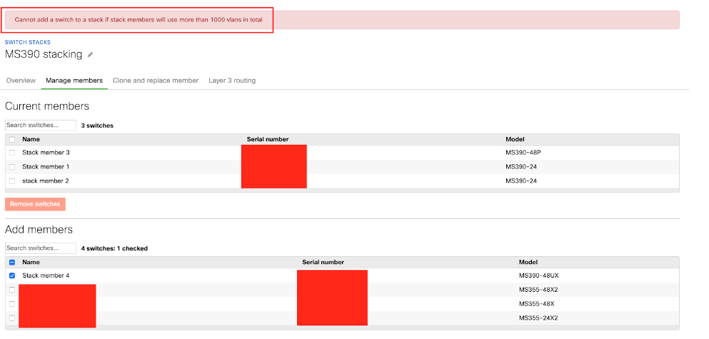
Before adding the new member to an existing stack make sure the total number of VLANs is limited to 1000. E.g., If an existing stack uses 1000 VLANs (e.g., VLANs 1-1000) and the new member switch ports are configured with an additional 500 unique VLANs (e.g., VLANs 2001-2500), the total number of VLANs in the combined stack would be 1500. This exceeds the limit. The dashboard will not allow the new member to be added to the stack and will show the following error:
-
Navigate to Switching > Monitor > Switch stacks and select the existing stack you want to add the switch to.
-
Check that the switches in the existing stack have all fetched the new configuration. To verify this, navigate to Switching > Monitor > Switches and select a switch in the stack. Look for 'Configuration status' in the column on the left of the switch details page and check if the status reads 'Up to date'.
-
In Switching > Monitor > Switch stacks > Manage members add the new switch to the existing stack.
NOTE: If adding a switch with Layer 3 configurations to a Layer 3 switch stack, there are two options:
- Clone the configuration from the added member switch onto the switch stack.
- Ignore the existing layer 3 configuration on the added member.

8. Power off the new switch, physically stack the new switch to the existing stack in a ring fashion and power it on.
It is highly recommended to keep the entire switch stack powered on during the addition of a new member to prevent the new member from assuming the active role.
Configuring StackWise Virtual
Prerequisites for StackWise Virtual
- Both switches in the Cisco StackWise Virtual pair must be directly connected to each other.
- Both switches in the Cisco StackWise Virtual pair must be of the same switch model.
- Both switches in the Cisco StackWise Virtual pair must be running the same software version.
- All the ports used for configuring a StackWise Virtual Link (SVL) must share the same speed. For example, you cannot configure a 10G or a 40G port to form an SVL, simultaneously.
Requirements
- Switches must be running IOS XE 17.18.1 or higher
- Between 2-8 StackWise Virtual link interfaces must be configured
- 1 dual-active-detection interface must be configured
- Each switch must have its own uplink interface.
- Uplink ports cannot be configured as an SVL or DAD interface
- The switch with the lowest MAC address will be elected as the active. This switch MUST have a root port if it is not configured as the root bridge.
- The switches will reboot multiple times during the StackWise Virtual setup to initiate the process and provision members. This is expected behavior.
- At this time, only Catalyst 9500 series models are supported.
Limitations
- The switch stack must be deleted prior to removing members from the network.
- A StackWise Virtual member cannot be replaced without first deleting the stack and reconfiguring
- Once StackWise Virtual has been configured, the SVL and DAD interfaces cannot be changed. To do so, the stack must be deleted and reconfigured.
Configuration
- Go to Switching > Switch stacks and click on the "Create stack" button
- Provide a name for the stack, select two C9500s from the dropdown, and then click the "Create" button

-
Select SVL interfaces

Selecting an SVL interface on one switch will automatically select the same interface on the other switch. -
Select DAD interfaces

Note - Selecting a DAD interface on one switch will automatically select the same interface on the other switch -
Click the acknowledgement checkbox and click configure
The configuration workflow will take approximately 30 minutes to complete.
Verifying StackWise Virtual Configuration Using the Cloud CLI
StackWise Virtual can be monitored and verified by using the Cloud CLI tool.
Verifying StackWise Virtual link interfaces

Verifying StackWise Virtual dual active detection interfaces

Verifying switch stack

Configuring a Flexible Switch Stack
Up to eight Meraki MS420/425 switches can be configured in a flexible stack to allow for high-speed communication between devices.
Flexible stacking is available on MS420 and MS425 switches, which do not have dedicated stacking ports. Any SFP+ interface on these switches can be configured as a stack port. On the MS425, the QSFP+ ports can also be configured as stack ports. Please note that 10 Gb/s is the minimum speed required to support flexible stacking. This section describes flexible stacking.
Only like-models can be stacked. For example, MS350-48 and MS350-24X can be stacked, but MS250-48 cannot be stacked with a MS350-48.
Physical stacking is available on MS150, MS210, MS225, MS250, MS350, MS355, MS390, MS410, and MS450 switches, which include dedicated stacking ports. For physical stacking, check the Configuring a Physical Switch Stack section of this article.
On the MS420 and MS425 series switches, you have the flexibility to use any of the front switch ports as either ethernet (default) or stacking. This option is available under the port configuration and can be easily modified by just selecting enable from the dropdown.
Converting a link aggregate to a stacking port is not a supported configuration and may result in unexpected behavior.
Once this configuration is made and the switches have downloaded the new configuration, it is recommended to follow a similar ring topology as mentioned above for the overall switch port cabling. Switch ports configured as stack ports will show up with a new symbol on the nodes status page to indicate that it is configured for stacking.
Flexible Switch Stack Configuration Steps
The following steps explain how to prepare a group of switches for flexible stacking, how to stack them together, and how to configure the stack in dashboard:
- Add the switches into a dashboard network. This can be a new dashboard network for these switches, or an existing network with other switches. For that, you may follow Adding and Removing Devices from Dashboard Networks article. Do not configure the stack in dashboard yet.
- Connect an uplink to each switch. Ensure that the uplink switch ports are different than the intended stacking ports.
- Power on all the switches, then wait several minutes for them to download the latest firmware and updates from dashboard. The switches may reboot during this process.
- The power LEDs on the front of each switch will blink during this process.
- Once the switches are done downloading and installing firmware, their power LEDs will stay solid white or green.
- Choose (but do not yet connect) two switch ports per switch to be the dedicated stacking ports. Switch stacks should be connected in a ring topology (as shown in the following image). Ensure that the stacking ports are different than the switch uplink switch port. Do not actually connect the switch ports yet. This will be done in Step 6.
It is recommended to configure and use identical switch port types as flexible stacking ports. For example, 2 x 10Gb/s (SFP+) or 2 x 40Gb/s (QSFP) interfaces can be connected together as flexible stacking ports.
Please note that 10 Gb/s is the minimum speed required to support flexible stacking.
- Configure the intended switch ports for stacking in dashboard under Switching > Monitor > Switch ports:
- Connect the switch stack via the intended stacking ports like the image shown in step 4.
- Navigate to Switching > Monitor > Switch stacks.
- Configure the switch stack in dashboard. If dashboard has already detected the correct stack under Detected potential stacks, click Provision this stack to automatically configure the stack.
Otherwise, to configure the stack manually:
- Click add one / Add a stack
Note: The MS AutoStacking process applies to flexible switch stacks as well, please see the note above regarding auto-provisioning.

- Select the checkboxes of the switches you would like to stack, name the stack, and then click Create.
- Disconnect all but one switch's uplink, which will be the uplink for the switch stack.
Viewing and Creating Your Stacks
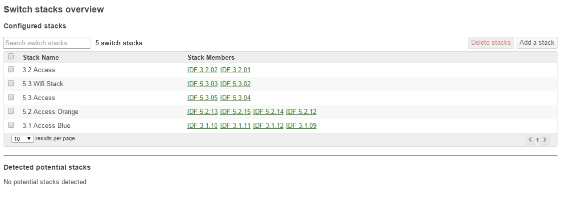
The Switch stacks page gives you quick access to all of the configured stacks in the network as well as provides easy configuration options for new stacks that are being deployed. Clicking on "Add a stack" or when there is a detected stack you will be able to easily configure a new physical stack.
Check the Health of the Stack
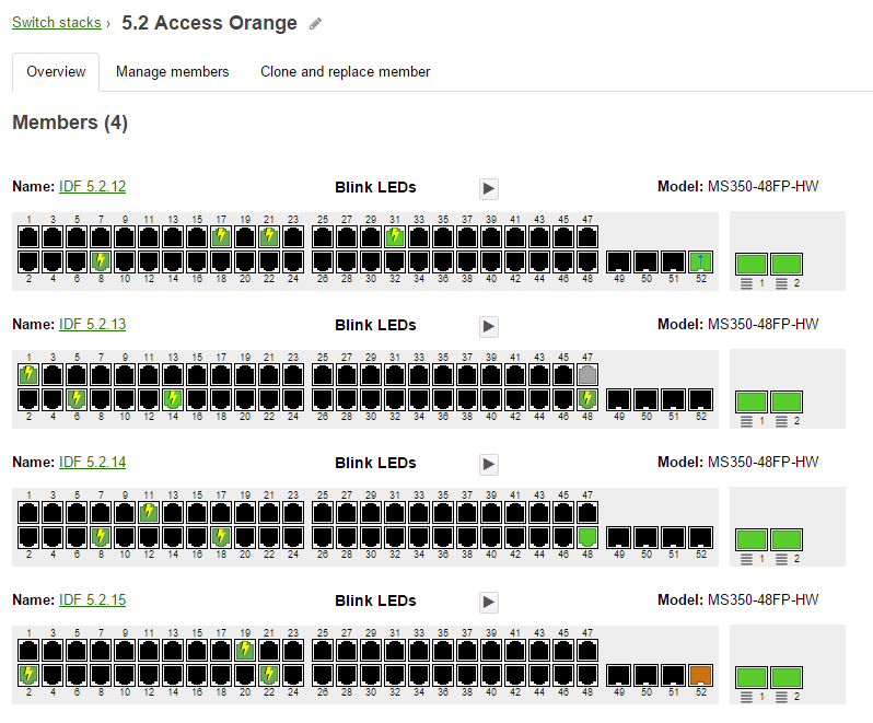
Viewing a Stack
In order to check the stack status visually simply click any row on the stacks List. This will take you to the overview of the stack selected. From here you can easily get a feel for connected switch ports and which switches are contained in the stack. We've included the capability to blink the LEDs on switches in the stack to easily indicate which switch it is for anyone who is on site looking at the stack.
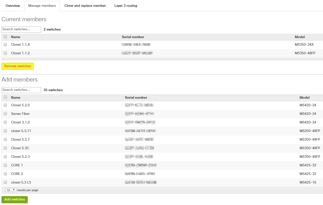
Managing Stack Members
To add or remove stack members simply click on the tab labeled Manage members and select the switch(es) that you want to add or remove from the stack and click either add or remove switches.
Deleting a Stack
To delete a stack in its entirety, browse to Switching > Switch stacks, from there select the checkbox of the stack in question and then click on the "Delete stacks" button.

You will then be prompted with a warning regarding Layer 3 configuration whether or not any such configuration exists on the stack:

Clicking confirm will then successfully delete the stack and return your switches back to stand-alone operation and configuration. It is recommended that the switches are allowed time to fetch configuration and are then powered down and stack cables removed.
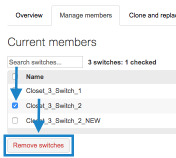
Removing a Stack Member
To remove a stack member from a switch stack, browse to Switching > Switch stacks, from there select the stack in question and head over to manage members. Select the switch that you would like to remove and then click on "Remove switches"

Note: If any of the following configuration existed on the switch prior to adding it to the stack, then they will be recovered upon removing it from or deleting the stack:
Link aggregates
Mirrored switch ports
Switched virtual interface (SVIs)
Internet Group Management Protocol (IGMP) snooping
Spanning-Tree Protocol (STP) priority
Attempting to remove a stack member from a pair of 2 switches will fail and result in a "Stacks must have at least 2 switches" error. Instead, the "Delete stacks" button should be used at the Switch stacks overview.

Viewing Switch Stack Role Information
When using physical or flexible stacking, one switch in the stack acts as the active switch, managing all of the stack functions such as spanning-tree. It may occasionally be useful to understand which switch is the active switch and which are stack members.
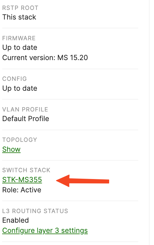
Beginning with MS 15.18, the stack role is displayed on the switch details page for an individual switch accessed from the Switching > Monitor > Switches page if the switch in question belongs to a switch stack. The "switch stack" section of the left-hand column displays one of three stack roles:
- Active
- Standby
- Member
Switches other than the MS390 have one active switch in the stack and all other switches are member switches.
MS390 stacks also have one standby switch. The standby becomes the active unit in the event of a failure of that switch.
Replacing and Cloning Stack Members
The steps below should be used for the following use cases:
- Replacing a Stack Member
- A stacked switch has failed and needs to be replaced.
- A stacked switch needs to be replaced in a stack with 8 switches.
- Cloning a Stack Member
- A stacked switch needs to be replaced, but the new switch should be up and running before the replacement occurs.
- A new switch needs to be added and requires the same switch port configurations of another stack member.
Note: All the following instructions are the same for both physical and flexible switch stacks.
Replacing and Cloning a Stack Member Video
Replacing a Stack Member
The following steps will clone the original stack member and remove it from the stack:
Note: If the active stack member is replaced there will be a short loss in connectivity when it is powered down while a new active member is elected.
Note: When the Active Member of a Classic MS Stack reboots, LACP links can take up to ~90 seconds to come back up when connected to certain neighbors (i.e. Catalyst/MS390).
Note: For Catalyst switches (including MS390) on CS firmware, it is required you power down the entire switch stack before adding / replacing a new member to avoid packet forwarding or configuration sync issues. This is only a requirement for stacks on CS firmware and not needed for stacks running IOS-XE firmware.
- Power off the stack member to be replaced
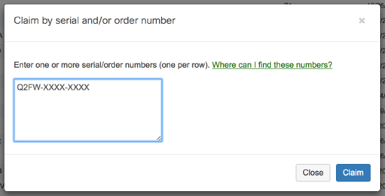
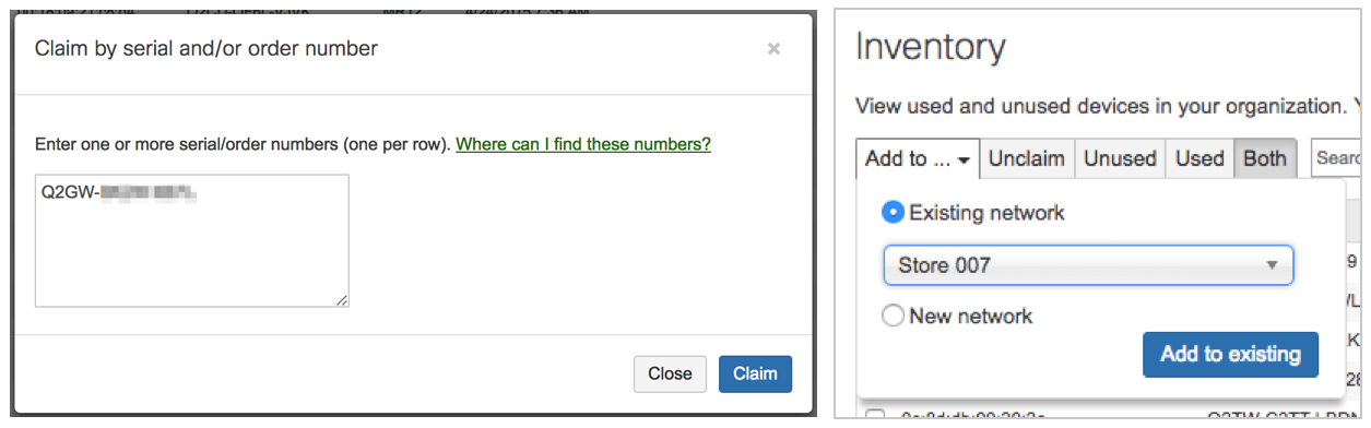
- Claim the new/replacement switch in the inventory (Using the Organization Inventory):
- Navigate to Organization > Inventory
- Click the Claim button
- Enter the serial number of the new switch. If replacing multiple members, list all serials

- Click Claim
- Add the switch to the network containing the stack
- Select the switch to be added to the network
- Click Add to...
- Select the network and Add to existing
Note: After the switch has been added to the network and before it is added to the stack or replaced, it should be brought online individually and updated to the same firmware build as the rest of the stack. Failing to do so can prevent the switch from stacking successfully. The configured firmware build for the network can be verified under Organization > Firmware Upgrades. A flashing white or green LED on the status light on the switch indicates that a firmware upgrade is in progress.
- (Optional) Edit the name of the new switch
- Navigate to Switching > Monitor > Switches
- Select the new switch
- Click the
 next to the title to rename the switch
- Clone and replace the stack member
- Navigate to Switching > Monitor > Switch stacks
- Select the existing stack
- Navigate to the Clone and replace member tab
- Select the source switch to be replaced
- Select the destination switch which will replace the source switch
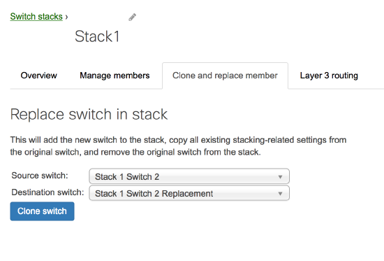
- Click Clone switch
- Physically swap the switches.
The old switch can then be repurposed as a standalone switch or removed from the network (Adding and Removing Devices from Dashboard Networks).
Cloning a Stack Member
The following steps will clone the original stack member without removing it from the stack.
- Claim the new/replacement switch in the inventory:
- Navigate to Organization > Inventory
- Click the Claim button
- Enter the serial number of the new switch. If replacing multiple members, list all serials
- Click Claim
- Add the switch to the network containing the stack
- Select the switch to be added to the network
- Click Add to...
- Select the network and Add to existing
- (Optional) Edit the name of the new switch
- Navigate to Switching > Monitor > Switches
- Select the new switch
- Click the next to the title to rename the switch
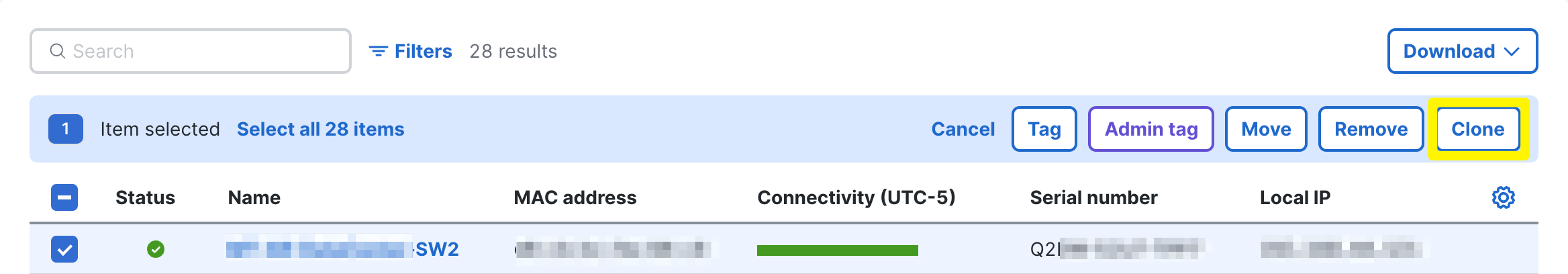
- Clone the stack member
- Navigate to Switching > Monitor > Switches
- Select the replacement switch
- Click on Clone as highlighted below
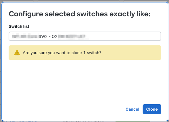
- Search for the original stack member name or mac address and select it.
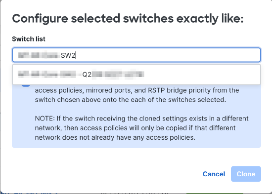
- Click Clone.
- Add the new switch to a stack.
- Navigate to Switching > Monitor > Switch stacks
- Select the existing stack
- Navigate to the Manage members tab. In the Add members section, select the switch to add
- Click Add Switches
Replacing a Stack Member for Device Configuration Source
If your new switch does not already have a cloud ID please follow the instructions here first to generate one.
- Do not power down the entire switch stack.
- Power off the faulty switch and remove it from the switch stack.
- With the replacement switch powered off, physically add it to the switch stack.
- Power on the new switch.
- Add the new switch's cloud ID to the same network as the switch stack.
- Select Device Configuration and enter the same credentials used for the stack.
- Wait several minutes for the dashboard to detect the new member and for it to appear in the switch stack.
Switch Replacement Walkthrough for Stacks Bound to a Template
Below are instructions for how to copy configurations from a failed switch that is part of a stack and where the network is bound to a template.
-
On the Organization > Configure > Inventory page, claim the new switch and then add the new switch to the existing network.
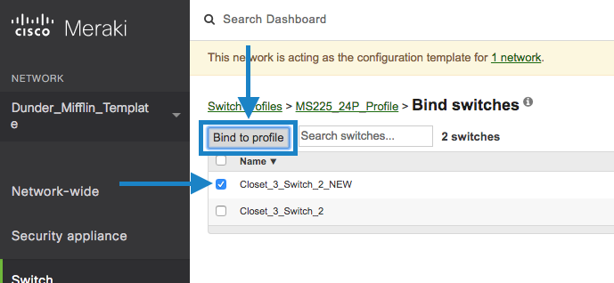
- Bind new switch to the switch template.
-
Navigate to the parent template in dashboard.
-
Navigate to Switching > Configure > Switch templates within that template.
-
Click on the corresponding template.
-
Click the Bind switches button.
-
Click the checkbox next to the new switch and click the Bind to switch template button.
- Firmware upgrade for the new switch.
-
Provide the new switch a physical uplink connection and then power it on. The new switch needs to be brought online as a standalone device, not yet added to the stack so that it can update its firmware.
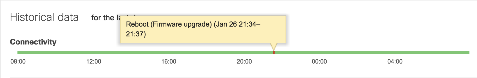
-
Confirm via the connectivity graph or Support that the switch has upgraded its firmware.
-
While the new switch upgrades, you may proceed with the below steps, stopping before Step 8 until the new switch has had a chance to upgrade.
- Obtain Current Configuration.
-
Navigate to Switching > Configure > Switch templates within the parent template.
-
Click on the template in question.
-
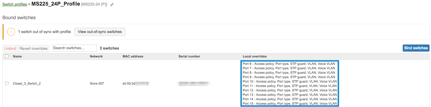
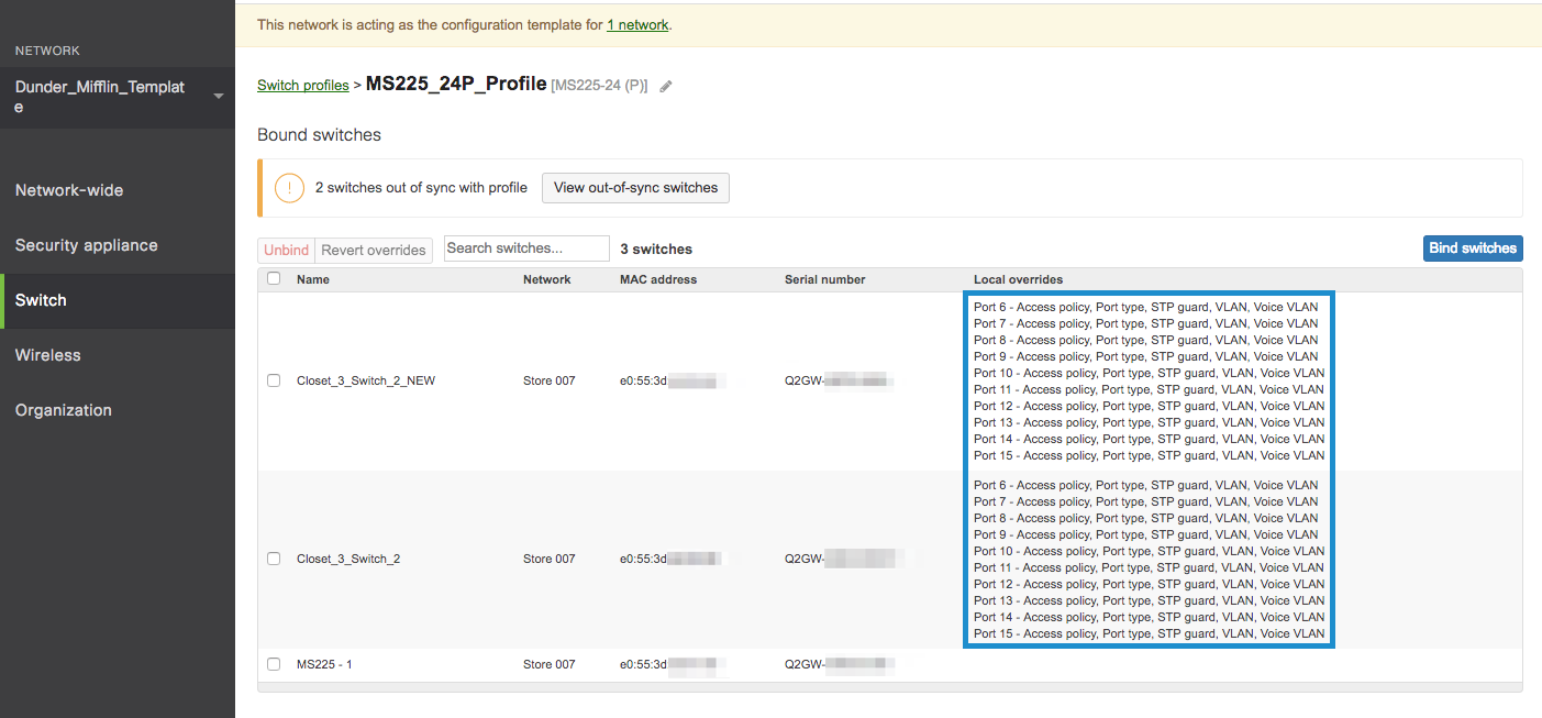
Filter in the Search switches… field for the name of the old switch.
-
Note the local override configuration. Save in a text editor for use in Step 5.
-
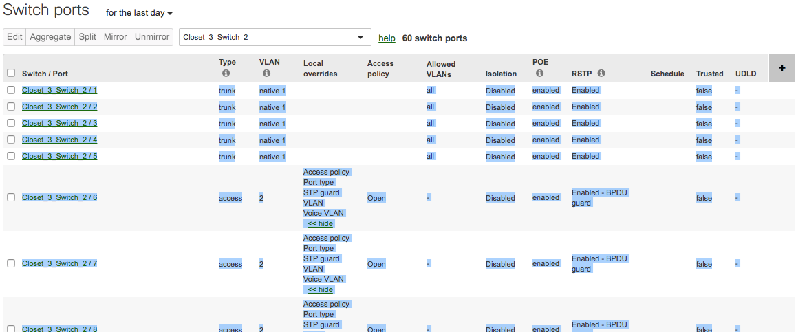
In the child network, navigate to the Switching > Monitor > Switch ports page.
-
In the Search switches… field, filter by the name of the old switch and select the below column options.
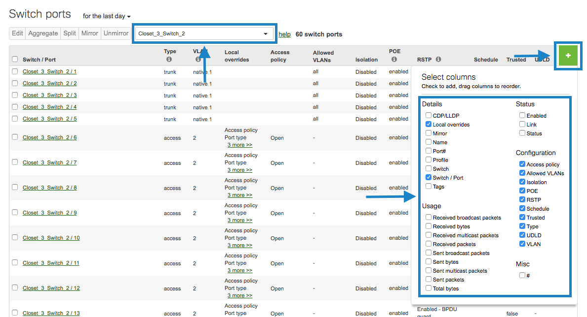
- Then, take screenshots of the port configurations or copy and paste into a spreadsheet or text editor application.
- Configure replacement switch.
-
On the Switching > Monitor > Switch ports page of the child network, configure the switch ports of the new switch based on the configuration gathered in Step 4.
-
Once complete, navigate back to the switch template details page from Step 4 and ensure that the local overrides between the old and new switch match.
- Power down the old switch.
- Unbind Old Switch from template.
- On the switch template details page, click the check box next to the old switch and then click the Unbind button.

- Add the new switch to the stack.
-
After confirming that the new switch has upgraded its firmware as mentioned in Step 3, power down the new switch.
-
In the child network, navigate to the Switching > Monitor > Switch stacks page.
-
Click on the stack in question.
-
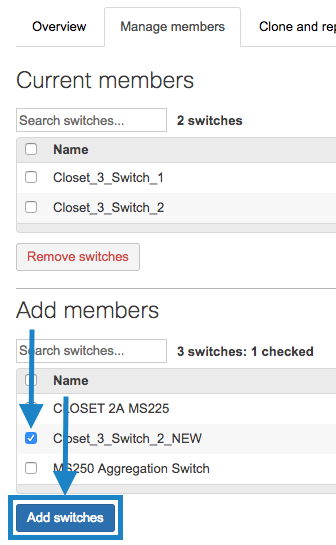
Click the Manage members tab.
-
Under Add members, click the checkbox next to the new switch and then click the Add switches button.
- Remove the old switch from the stack.
-
In the child network, navigate to the Switching > Monitor > Switch stacks page.
-
Click on the stack in question.
-
Click the Manage members tab.
-
Click the checkbox next to the old switch and then click the Remove switches button.
- Physically cable and stack the new switch.
- Power on the new switch.
Layer 3 Interface Configuration
For configuration details and caveats regarding Layer 3 switch stack routing, please reference the article MS Layer 3 Switching and Routing.
Common Alerts
Ensure all stack members are configured on dashboard, online and connected via their stacking ports.
Note: If connected and configured correctly, the alert will disappear within up to 1 hour. If the error persists, please contact Cisco Meraki Technical Support for further troubleshooting.
This switch's current stack members differ from the dashboard configuration/Misconfigured Switch.
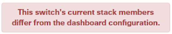

This can occur in the following scenarios:
- Stack members are configured on dashboard, but not all members are connected via their stacking ports.
- A stack member has failed or is powered off.
This switch is not connected to a stack/Switch not connected to stack.
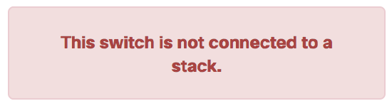

This can occur in the following scenarios:
- The switch is configured on dashboard as a stack member, but is not connected to a stack.
This switch does not have a stack configuration/Unconfigured Switch.
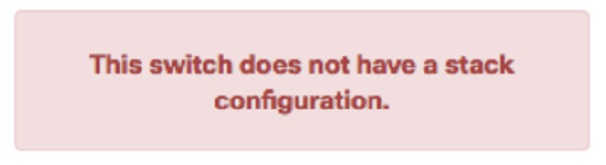

This can occur in the following scenarios:
- The switch is physically connected as a stack, but not configured on dashboard as a stack member.