
Network Client Sampling
Overview
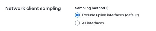
Meraki MS Switches by default will disable sampling of clients and traffic on the detected uplink interface to ensure that reporting data is accurate. The discovery mechanisms were to identify MS to MS links, and disable sampling dynamically. This works well for end-to-end Meraki networks, but in networks where there are ANY intermediary devices, or Catalyst + Meraki deployments, client connectivity and locations could become inaccurate. To address this, we have introduced a new setting that allows customers to statically control sampling at the Switching > Switch settings menu:
Any new networks created as of May 15th, 2023 will be configured with the new default of disabling sampling on all uplinks. If there are any issues with the data, or a desire to sample on uplinks (trying to track clients connected to a non-Meraki switch upstream as an example) you can enable sample all interfaces, where we will sample on any non MS to MS uplinks.
The outcome of enabling sampling on all interfaces may introduce variability to the accuracy of client locations however, especially if the uplink is an aggregation point for multiple MS devices in an L2 topology.
How sampling has worked historically:
In an MS network, the Client details page reports the client's last known switch and port number:
Figure I.

This Dashboard information is based on the most recent MS switch to see the source MAC address of the client ingress one of its ports.
A client device's last known port could change frequently, showing up on different MS uplink ports, if a device is not directly connected to an MS switch.
Lets suppose you have a network comprising of MS switches and non-Meraki switches in which frames sent from devices connected to your non-Meraki switch must ingress an MS switch to reach their destination, as per the diagram below.
Figure II.

In the example shown in Figure II. device A sends a frame to device B. This frame will ingress MS-1 port 1 and this will be reported as last seen. Immediately following communication with device B, device A sends a frame to device C. The frame will ingress MS-2 port 2 and this will change the last seen location to this switch and port combination.
When a wireless device is roaming between APs connected to different MS switchports. The mobile client will always appear as Last seen on the most recent switchport to receive frames from the mobile client.
Figure III.

In the example shown in Figure III. a mobile client moves from AP1 to AP2 to AP3 respectively. If the client is sending data continuously they will first be reported as seen on MS-1 port 1, then last seen on MS-1 port 2 and finally last seen on MS-2 port 1.